3 Customer Need Identification
Product design and development process starts from a clear, reliable, and comprehensive definition of the problem at hand. The design team is expected to have a systematic procedure in place to ensure the voice of customers are clearly understood and interpreted to avoid any possible misunderstanding of their needs. In this chapter, we introduce a few commonly used tools to identify the customer needs. Besides, some gathering information techniques will also be presented.
Identifying Customer(s)
The design team is expected to broaden the definition of customer(s) to ensure the final product will satisfy the needs of those who are receiving or using the product. It is important to consider the product life cycle, from the manufacturing stage to the end of life of product stage, to ensure the design team identifies all potential customers. One should note that an “end user” refers only to a person or organization who buys or uses a product(s). The design team should consider all resources/personals required to manufacture, assemble, package, ship, and recycle a product to include all potential customers and their needs when the team designs and develops a product.
Gathering Information
During different phases of a typical product design and development, the design team needs to gather the required information to explore and understand the product in terms of its performance, benchmarking, generating the design concepts, and the likes. Each design team practises different resources according to the product types. However, the followings are a list of commonly used resources that new designers can consider gathering the information:
Technical literature. Examples
- Trade magazine
- Published journal/conference papers.
- News letters
- White papers
Library resources. Examples:
- Handbooks
- Textbooks
Product specs. Examples:
- Catalogues
- Brochures
- Manuals
- Reveres engineering of a product
Professional trade website. Example:
- Thomas Register
Professional organizations. Examples:
- SME
- ASE
- ASME
- IEEE
Patents. Examples:
- ic.gc.ca
- ipic.ca
- uspto.org
Google Scholar
Development of Product Specifications
The crucial step in a design and development of a product is to understand the customer’s needs and wants and interpret them into several measurable engineering parameters such that the customer’s needs and wants are achieved. To do that, the design team must describe the product from the design perspective carefully. A product is described by its three main design terms:
- Design parameters
- They signify those parameters that govern the overall form and performance of a product.
- Design variables
- They imply those variables that the design team have option to manipulate to achieve the required product specifications/design parameters.
- Design constrains
- They are a subset of design parameters that the design team can not manipulate and are considered fixed.
The design team should prepare a list of customers needs and wants in the beginning of the design process to ensure the voice of customer has ben heard accurately. In general, the customers needs and wants can be categorized and viewed from four directions in design process:
- Product performance
- It refers to overall performance of the product comparing to its specified characters.
- Time
- Depending on the product, this term may refer to different attribute of the product such as lead time, life-time, and design time.
- Total cost
- It refers to all product design attributes contributing to the total design cost of product.
- Product quality
- This term is a qualitative term representing different aspect of quality as described by customers such as features, reliability, and performance.
One should note that the customer needs and wants (i.e. requirements) are largely independent of any specific product that the design team develops. In other words, the customer needs and wants are not dependent to the design that the design team finally completes. However, the product specifications, essentially, depend on the final design of the product. The development of the product/engineering specifications is a two-stage process. First, a set of target engineering specifications is developed based on customer need and wants and then, at the end of the design process when the design is finalized, the engineering specifications will be finalized based on selected concept, testing and trad-offs made during the deign process.
Identifying the customer requirements precisely and establishing the corresponding design parameters to address them is a crucial step in the design process. One should note that having a general knowledge of what customer or end user wants is not enough to ensure appropriate concepts are generated/selected in the design process. Concept generation phase of the design process begins with a well-established and well-defined product specification and engineering parameters.
Quality Function Deployment (QFD)
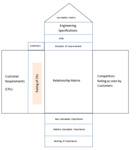
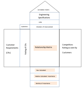
Quality Function Deployment was developed in Japan in the mid-70s. It is considered a comprehensive tool that a design team can use to organize the information flow in the design process to understand the design problem. It helps the designers to hear the voice of customer, quantify the customer needs, develop the design parameters, corelate the design parameters, develop the product specifications, and bench mark a new product.
, Rating of CRs, Relationship Matrix, Engineering Specifications, Competitors Rating, Raw Calculated Importance, Relative Calculated Importance, and Ranking of Importance.")
Development of QFD
One should not that QFD is an important dynamic design document that the design team generates during the design process and need to be updated as more information is provided/gathered about the project. Besides, the level of detail of a QFD is subjective to the type of the project at hand and not all the projects need a full developed QFD with all information/details presented in this section. The following sections represent the general guidelines to form a QFD.
Step 1. Identify the customer(s)
- List all the customers who their requirements are important and critical to be considered.
- In most cases, the end users are the most important customers to be considered. However, the design team need to study potential customer inside and outside of the enterprise. For examples, the design team may have to look at manufacturing, quality control, shipping, and other stakeholders to ensure their critical needs will be considered as well.

Step 2. Determine the customer requirements
- The common practices to gather the information from customers include interviews, observation, focus group, and surveys.
- Avoid vague statement to describe the customer requirements.
- Group the customer requirements properly, if required.

Step 3. Determine relative important of CRs
- Identify the customer to whom each CR is important.
- Develop a weighting factor to quantify the important factor. One approach is to use the scale of 1 to 10
Step 4. Market benchmarking (How satisfy the customers are now)
- The objective of this section is to address the competition and evaluate how satisfy are the customers with the existing products in the market.
- Depending on the targeted market, the related competitors should be selected carefully.
- Appropriate weighting factors need to be developed to quantify the satisfaction of customer. One approach is to use the scale of 1 to 5.

Step 5. Generate the Engineering specifications.
- The objective of this step is to generate a set of engineering specifications to address the customer requirements.
- The unit and the direction of improvement need to be identified for each engineering specification. The direction of improvement can be represented by arrows (i.e. more is better or less is better).
- Each engineering specification should be measurable and address at least one customer requirement.

Step 6. Relate customer requirements to the engineering specifications.
- Relationship Matrix: Assign appropriate weighting factors for each customer requirement with respect to the corresponding engineering specification.
- Raw Calculated Importance: For each customer, multiply the importance weighting factors developed in step 3 (i.e. values from 1 to 10) by the values assigned in Relationship Matrix. Sum the weighted values for each specification and let call the value “Customer-Engineering Specification Score”.
- Sum all “Customer-Engineering Specification Score” and call it “Customer Score”.
- Relative Calculated Importance: Normalize “Customer-Engineering Specification Score” by dividing them by “Customer Score”.
- Ranking of Importance: Rank the engineering specification based on the results of normalized value.
Step 7. Identify relationship between engineering specification.

- Identify the degree of dependence between the engineering specification at the top of QFD.
- Use a convention to represent those dependency. For example, you can use (++) for a strong dependency when increasing one engineering specification will significantly increase the other one. You can use ( + ) , (-), and ( – -) based on the correlation among the engineering specification accordingly.

Sample QFD. Adopted from a student project at BCIT “Design of a 3D Printing Heated Bed .”
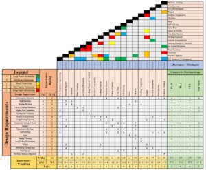
Sample QFD. Adopted from a student project at BCIT “Fully Automated Tree Seedling Planting.”
