1 Introduction to Engineering Design
Engineering design is a process of materializing concept ideas by creating something new, adding/improving a feature(s) to a product to improve its performance, or integrating parts and components in a new configuration to address a need of customer(s). Generally speaking, engineering design is a multidisciplinary task performed by a team of professionals who are applying their different domain knowledge in a systematic way through a design process to satisfy particular customer needs. This design process is an information processing system that starts from generating a wide set of potential solutions/alternatives and then narrows down those alternatives based on some criteria until the final solution/design is developed to satisfy the need of customer(s). Implementing a well-defined design process in a culture of an organization is a necessary condition to ensure the quality of the products and minimize the time to market as well as reduce the overall cost of product design and development. The cost of product design is very little comparing to the total cost of manufacturing, marketing and other related costs of a product. However, one should note that any decision made in the design process of a product has a major effect on the total cost of its manufacturing and assembly.
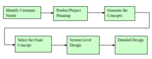
A generic design process includes: (i) develop a systematic approach to identify the customer needs; (ii) utilize project planning techniques to phase the design process with clear milestones; (iii) generate design concepts; (iv) develop criteria to narrow down the alternatives; (v) create system level documents for the selected concept; and (vi) prepare detailed design documentations such as shop drawings and bill of materials.
Ken Wong, MECH 4490 Lecture Note, BCIT 2006
A well-defined and well-structured design process can be used as a baseline for other managerial, project planning, budgeting, and continues improvement activities and tasks as illustrated below.
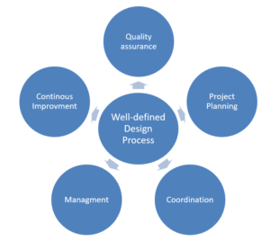
Quality assurance. A well-defined design process specifies required phases and checkpoints to insure the design will meet the expected quality.
Project coordination. A well-defined design process acts as a master plan to coordinate the numerous tasks from the start to the end of project.
Project planning. A well-defined design process has natural milestones for completion of each phase.
Management. A well-defined design process is a benchmark for measuring the performance and identifying the problems.
Continuous improvement. A well-defined design process helps to document organizational development activities to identify the opportunities for improvement.
Type of Design Projects
There are several types of design projects. Three commonly implemented type of design projects are explained below.
Novel design project. In this type of design project, designers use a novel concept to meet a need(s) of customers. They may end up with an invention to solve the problem at hand as the solution employs a new and novel approach or concept. However, in practice, vast majority of engineering design problems are solved without employing any novel ideas!
Improvement/optimization design project. The solution to most of engineering design problems is based on either redesigning an existing product/part or adding a new feature to a product to improve its performance, functionality, cost, or safety.
Catalog design project. In this type of design projects, designers will select and integrate off-the-shelf and/or standard components into their design considering the customer needs and availability of those components based on vendors’ catalog.
Product Life Cycle
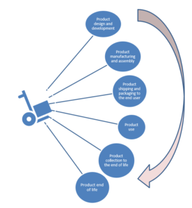
Regardless of type of design project, each product has its own life as follows:
- Product design and development
- Product manufacturing and assembly
- Product shipping and packaging to the end user
- Product use
- Product collection/shipping to the end of life
- Product end of life
Design Philosophy
The nature of a machine, the type of industry, and the accepted design standards would affect the design philosophy used. Factors affecting the design philosophy include:
a) The volume of machine to be produced. Components to be mass‑produced should be designed with ease of assembly and automation in mind. Automobiles, light bulbs, hand tools, and office equipment are a few examples to mention.
b) The area of usage. Would it endanger life? Would cost of failure be high? Critical components in a bridge must have a very high safety factor are examples to mention.
c) Components which are inaccessible or critical must have a high reliability.
d) Keep in mind that high tolerances mean expensive production. In aircraft components, such high precision is required.
e) Functional vs. Aesthetics. For consumer product and architectural design, aesthetics has a major effect on a design philosophy.
f) Market Requirement. Components could be designed to have a long or short life. From a producer’s point of view, short life could mean more products can be sold at a lower cost. Long life would be more beneficial for the consumer, though at a higher cost.
Feasibility Study
A feasibility study is an economical method to determine if a project or product design should go ahead or not. Sometimes many feasibility studies are needed for major projects or product designs. Building a pulp mill, a new power station, mine, oil pipeline, producing a new automobile re few example to mention.
A feasibility study or studies are usually done to :
- Establish the “feasibility” of a project or product in terms of its technical practicality. ie. Do we have the technology to come up with a cost-effective design?
- Analyse the economics (such as capital and operation cost analysis, present worth, payback, rate of return etc.),
- Determine the potential impacts (environmental, operational, labour, benefits etc. ).
Engineering Design Education
Traditionally, engineering education as taught in universities and colleges relies mainly on an “equation solving format”, that is, students are given a problem, its assumptions, and input data needed for solving an equation or equations. Students normally interpret the wording of the question and then they use an appropriate formula or procedure to obtain a numerical answer. A simple illustration of this approach is shown below.
Classroom Approach (Problem Solving Approach)
Given: A power transmission shaft rotates at 400 rpm, and is transmitting 500 ft-lbs of torque. If the safety factor n = 2, and use AISI 1020 HR steel, what is the diameter of the shaft needed? Use the ANSI/ASME Formula for shafting.
Solution:
Diameter d = [ formula ] = 2.1“ Answer.
Real Life Problems (Decision Making Approach)
Engineering practice in real life is seldom so simple. An illustration of a real-life engineering problem:
Design a steel power transmission shaft to be used in a chemical slurry mixer in a pulp mill. Given information includes the size of the mixer tank, and the chemical composition of the slurry (a water and pulp fibre mixture).

Note the lack of information and data.
Solution Process:
a) Select an appropriate material. Should it be AISI low carbon steel, high strength, chrome-moly steel, or should it be hot-rolled, cold drawn, OQT, etc., what about ASTM or ANSI grades ? How about stainless steel or a special steel grade (chemical may be corrosive)?
b) Estimate the torque load on the shaft. What is the resistance or load that the rotating mixer shaft would experience when churning the slurry? Is the load static, fatigue, or both, or none, or …. ?!?
c) Are there engineering codes governing this design ? What safety factor should I use?
d) What is the consequence of failure? Would some one be killed? What is the cost of downtime?
e) Calculate the shaft diameter. What method should I use? Constant Life fatigue Diagram, ASME Formula? Ask for help? Should I check for deflection? What about critical speed? Should I talk to the supplier to buy their off-the-shelf stock sizes? ..?!?
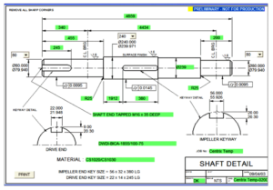
f) Draw the shaft geometry showing all details. Decide on the types of bearing used for support, the fits and tolerances needed for all the dimensions such as the diameters and the lengths.
g) Specify material used, shoulder and key way details, shoulder fillet radius, groove details, shaft The Life of Product

Ken Wong, MECH 4490 Lecture Note, BCIT 2006
Engineering Theory versus Real Life Practices
In engineering design, the approach used in schools is, as illustrated above, very different from real life, industrial practices. Some of theses differences are:
a) In a classroom, students are given all needed information to arrive at the solution fairly quickly, whereas in practice, information is not readily available. Young designers may not know where to begin in the design process. For example, in stress analysis, loads are normally given; students will then calculate the stresses based on certain areas in a material. In practice, estimating loads can be a major step where there are many uncertainties and assumptions associated with the estimate. A designer has to decide what assumptions and simplifications to make, what references are available, and what are the accepted codes in practice.
The process ultimately boils down to a decision making, rather then a numerical computation process. This decision involves at times compromise among various conflicting factors, and meeting different constraints.
b) Consequences of Errors. In a classroom, there is much less urgency to ensure error-free results because assignments are hypothetical. In practice, design errors could mean loss of job, income, production time, loss of limbs, or even life.
c) In school, when a student cannot solve a problem, help is readily available. In practice, a young designer would have some guidance from the immediate supervisor, though somewhat limited because most people are busy.
d) In school, the “service” nature and reality of engineering design is not stressed, sometimes leading to the wrong perception of a “Service” means that designers provide a service to certain groups such as other departments in the same company, outside clients etc. The reality of engineering design work is mostly mundane, routine, repetitious, and sometimes tedious. Most professional careers such as doctors, lawyers, accountants etc. provide some form of services to clients.
e) Some students have a pre-conception that computers are all-powerful and can solve all their problems, including personal ones such as astrology, and dating. A computer is just a tool, a dumb machine which follows instructions according to pre-programmed instructions. You, the designer still have to solve the problem. No CAD, word processor, or software tool can design for you; they will only facilitate or help in your design. For example, a good knowledge of AutoCAD by itself is not sufficient for landing a job in design; it must be combined with strong analytical and engineering skills.
There is also a great danger in accepting outputs of a computer program as being correct and using them as the basis for formulating the design. Outputs from a computer program tend to be very organised and impressive, with lots of colourful graphics and pages of “10 digit” numbers. If these data are not supported by good engineering experiences and judgements, a design based on computer-generated values would be poor, with sometimes disastrous results!
Many structural designs are done using finite element analysis (FEA) which typically generates pages of numbers giving values of deflections, stresses, at each node of the structure. These analyses are most likely done by young designers and engineers as they usually are trained in schools with the latest software. Unfortunately, if the FEA results are not backed by strong engineering experiences, software outputs are worth no more than the weight of paper they are on.
f) Drawing skill
In schools, students normally receive 1 or 2 courses in drafting, and subsequent courses traditionally do not involve drafting skill. In practice, drafting or drawing is a major skill needed in mechanical design. After all, tradesmen and production engineers do not really care about the analysis or computation involved. They just build the parts as described in the drawings.
Drawing is a common medium of communication among all parties in engineering, and is a skill which takes years to become proficient.
Analogy: If you were to take Japanese lessons for 6 months, with no former background in Japanese, would you claim Japanese fluency after 6 months? Lesson: You can be a reasonably proficient CAD operator after 6 months of CAD training, but you most likely cannot draw properly after 6 months of drafting lessons.
Transition from Theory to Practice
Because of these differences, students, after graduation, may find it an unpleasant experience when entering the work force. In order to facilitate a smooth transition from theory to practice, the following approaches can be used:
Real Design Projects. While students are still in school, realistic design projects are given. Students are encouraged to develop self‑learning ability, an analytical mind that can think through a problem on their own. “Babysitting” by instructors must be minimised.
Real-life experiences
- Team Work. Real‑life engineering is team work which relies heavily on information gathering, knowledge of information sources (Catalogues, contacts, library etc.), and sharing of information ‑ Hence the term “Catalogue Engineering”. “Lone ranger” mentality has no place in engineering.
- Judgement / Decision Making Ability. When information is not available, sound engineering judgement or decision must be used. i.e. Educated guess based on some rationalized approach and experiences.
- Sig figs keep in mind that typical engineering calculation results might be idealised and would have a margin of error, and there is no need to carry calculations to many digits. Therefore as a general rule, for most applications, use about 3 significant figures only and appropriate safety factors according to applicable design codes. Exceptions: Precision manufacturing, fits and tolerances, geometric tolerances, thermal dynamic calculations etc., where more sig fig’s are needed.
- Restraints. Real engineering has time, budget and resource restraints. Design process therefore should be carried out under these restraints. Time management skill, project management, efficiency and discipline should be developed while still in school.
- Help. Normally, help can be readily available from fellow workers or supervisors to a certain extend. If you are stuck, do not be afraid to seek help. At the same time, you must show other people that you are doing your best before asking. ie. Think, analyze, if you are stuck, then ask. In a classroom, students could keep on asking questions without thinking and answers are readily given. Such a practice is definitely not recommended in work.
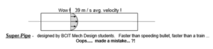
- Gut Feel. Develop a “gut‑feel” or instincts of what the expected results or answers of your design should be. If your calculations are different from what you would expect, find out why. A good “gut‑feeling” is gradually developed through experiences. E.g. Your calculation of the average water flow velocity in a pipe comes out to be 39 m / s. This value obviously does not make sense! Think of it, 39 m / s = 140 km / hr! For general piping design, the average pipe velocity for liquid would be turbulent and in the range of a few m / s.
- Common Sense. Develop a common sense approach to problem solving. Your common sense may turn out to be one of the most useful tools. For example, a sophisticated stress analysis indicates that a certain steel wide flange shape is needed to support a pure vertical load. The answer is probably Ok if we live in a perfect world. But common sense would tell you that there is no such thing as a pure vertical load and the fact that no beam is perfectly straight or horizontal, and beam flanges can be warped or out of square. Also, any eccentricity in loading could create flange bending stresses and lateral (horizontal) stresses in the beam where the area moment of inertia is much weaker.
- Quick Layout / Detailed Drawing. The ability to do both quick scaled layouts and detailed drawings needed for production and assembly.
- Communication, Students must develop a good communication skill, both oral and written. Good English is an essential skill that all grads must have. In fact, employer surveys always rate communication skill as one of the most important employment skills.
- Learn More. Keep in mind that after BCIT, your learning process just begins. There is a lot more to be learned yet.
If there is one skill that you muse obtain in school, it is the problem solving skill; that is, ability to think and learn on your own, and come up with solutions to problems that are practical, and simple to implement. Sheer head knowledge is secondary compared to this skill.
Design Organization
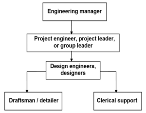
After graduation, a technologist can join a company at different job classifications. For example, in a typical firm, he/she might start as a draftsman, junior designer, or an engineering clerk (duties include drawing management, organising design standards, putting together contract documents, etc. i.e. Doing every thing needed to keep the engineering operation going smoothly.) If he/she works for a supplier of equipment, he/she might work as a designer / draftsman in the engineering department, part of the maintenance team, or an operator / helper on the shop floor. In any engineering organisation, however, the general structure would likely comprise the following personnel:
Ken Wong, MECH 4490 Lecture Note, BCIT 2006
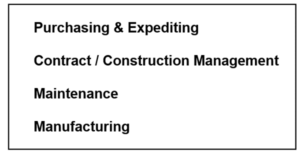
Bigger companies can have the following departments as well: