4 Concept Generation/Concept Selection
A general mechanical design process was represented in Chapter 1. As shown below, the conceptual design phase begins once the customer requirements have been identified and established. This phase can be accomplished by generating several conceptual designs and then selecting the final concept to move to the next phase of the design process.
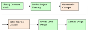
Ken Wong, MECH 4490 Lecture Note, BCIT 2006
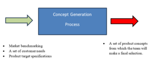
As shown below, this phase starts with the results of the customer needs/requirements phase developed in Quality Function Deployment of the project. Three key results can be categorized as:
- Market benchmarking
- Customer requirements/need statements
- Product specifications
Functional Decomposition Approach
Functional Decomposition design approach is a systematic method to generate the design concepts based on physical behaviour and functional requirements of the product leading to grouping the components of a product in a logical way. We will use this approach in this text to generate and develop the conceptual designs. The fundamental principle of this method is to focus on the required function(s) to generate the ideas in the design process and the product shape will follow the required function(s).
In other words, the conceptual designs are the means to provide required functions. Thus, mechanical designers need to identify the required functions and decompose them to be able to design, generate or implement alternative techniques, mechanisms, parts, equipment, and systems -depending on the types of projects- to achieve those functions.
The following steps are recommended to generate Functional Decomposition Diagram:
Step 1. Draw a single block box to represent the product and identify its inputs and outputs
Step 2. Split the single block box into more elements and identify the function(s) of each element
Step 3. Organize and connect the elements in a logical way such that each element completes a function(s) leading to another element.
Step 4. Repeat the process of splitting and organizing the elements as described in step 2 and 3 until the design team agrees on that each element and corresponding function(s) are simple enough to generate concepts to perform its desired function(s).
For instance, in a design and development of a Large Format 3D printing machine project (a student 2nd year capstone project at BCIT), three elements can be identified and related functions are listed. This is an example of implementing step 1 and 2 of above process toward developing Functional Decomposition Diagram.
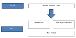
Heated Bed required functions
- Provides an adhesive surface that the first layer of printed material can bond to
- Supports the heater which converts electrical energy into thermal energy which heats the bed. Heating the bed reduces deformation of the part during printing.
Y-Axis guide system required functions
- Supports the heated bed.
- Provides horizontal linear motion of the heated bed in the Y direction.
Base Frame required functions
- Provides a rigid support of the Y-axis guide system.
- Provides a rigid support of the Z-axis guide systems.
- Supports the enclosure housing the main components of the controls system.
- Supports the chamber.
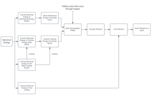
Two more examples are shown below to illustrate how two student design teams generate Functional Decomposition Diagrams for two projects.
Example 1. Functional Decomposition Diagram at its early stage for designing a desktop extruder.
Example 2. Functional Decomposition diagram at its early stage for the project “Hydrokinetic Generator”

Concept Generation
A conceptual design is an approximate representation of a product or mechanism that include chosen technology, working principle, and its overall form/configuration. It is expected to present the design idea to show how the product or mechanism will perform and satisfy the expected function(s) developed in Functional Decomposition Diagram. The design concept can be represented as a sketch, 3D model, or even a physical prototype.
Concept generation is a design activity based on a simple way of thinking “Form follows Function”. As mentioned, functions represent “what” the product expect to do. On the other side, forms represent “how” the product will do the function. Thus, the concept generation focuses on expected function(s) of each element of Functional Decomposition Diagram. The design concepts are the means for addressing those functions.
The followings are the list of commonly used resources for concept generation activity:
- Lead users who benefit from the improvement and are source of innovative ideas.
- Benchmarking
- Experts who can provide the technical experts as well as the experienced customers.
- Patents
- Literature (technical journals, trade literature, conference proceedings, deign handbooks…)
Brainstorming is a commonly used method to generate the design concepts. It is based on integrating the knowledge and creativity of individual and teams. Brainstorming is a carefully structured and managed process to achieve its goals. The followings are some general guidelines for a productive brainstorming session:
- It is recommended that each team member work alone first on generating ideas before coming to the brainstorming session.
- Group brainstorming is a powerful tool for refining the design concepts.
- Suspend any judgment during the session.
- Generate a lot of ideas.
- Do NOT ignore or underestimate the ideas that may seem impracticable at this stage.
- Use appropriate media such as sketch, 3D models, or even prototype to demonstrate the idea.
- Combine the ideas wherever it is possible.
As mentioned, a design concepts should include acceptable level of details and information including three main attributes as follows:
- Description of technology
- Overall working principles
- Overall shape or structure
Examples of design concepts developed by students are shown below.

“Design of a suspension system”, Andrew Young et all, Class of 2018
“Design of a suspension system”, Andrew Young et all, Class of 2018
Morphological Approach
The word “morphology” means the study of shape and structure. Morphological approach is fundamentally based on dividing the overall design problem at hand into subsystems and subproblems such that each subsystem will address a required function(s) developed in the functional decomposition stage. Then several design concepts will be generated for each subsystem. A morphology chart will be developed to visualize those design concepts aiming to combine and evaluate all possible combinations.
The general morphological approach can be accomplished as follows:
- Decompose all the required functions and develop the functional decomposition diagram.
- Divide the overall design to subsystems such that each required function(s) can be met in a logical way by related subsystem.
- Develop design concepts for each subsystem.
- Combine the design concepts to outline the overall design.
A morphology chart developed by a team of students for the project “Hydrokinetic Generator” is shown below.

“Portable Hydrokinetic Generatotor”, Darryl LeBeau et all, Class of 2012
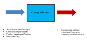
Concept Selection
Concept selection is a design activity to evaluate the design concepts with respect to the customer requirements and other criteria developed during the design process. It includes comparing the strengths and weakness of the design concepts to select one or more design concepts for more improvement and analysis at the next phase of the design process.
The main challenge of the concept selection stage is to develop the criteria to evaluate the design concepts accordingly. The criteria are strongly dependent on type of the project and customer requirements. Some general guidelines to develop the criteria:
- Consider the customer requirements and needs as a base to define and develop the criteria.
- Consider the constraints and limitations of the company such as cost, in-house manufacturing capabilities, liability, insurance and so on
- Investigate and benchmark the similar products of the competitors.
In order to evaluate several design concepts relatively with respect to a set of criteria, a reference design concept is used as a benchmark. Here are some examples:
- Appropriate standard
- Available competitive product in the market
- Uncomplicated concept
- Similar product or outdated product in the market
- Best-in-class product in the market
Pugh Chart
Pugh chart is a relative comparison and useful method to identify the most favorable design concept(s) based on selected criteria. It uses a reference design concept to compare a design concept among alternatives. A simple relative evaluation of each design concept is performed as shown below.

Example of Pugh chart is shown below.

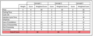
Weighted Decision Matrix
Weighted Decision Matrix is a systematic approach to assess the design concepts through implementation of a wight factors to the criteria and evaluating them to determine the score the levels to which each design alternative meets the related criterion. Table shown below represents an example of a typical weighted decision matrix.

Example of Weighted Decision Matrix is shown below.
It is strongly recommended that the design team assess the final decision and design process through holding a “design review” session to evaluate the selected concept at this stage. The followings are a few guidelines to consider:
- Each team member is expected to feel comfortable that the selected concept meets all customer requirements and all relevant technical issues and technologies have been evaluated and all related design parameters have been considered.
- The design team should make sure that the criteria have been selected properly and no criterion is missing. Besides, the design team must double check the weighted factors as they have significant role in the concept selection process.
- The design team must review the failed concept(s) at this stage to ensure that a good concept(s) was not degraded and investigate the possibility to integrate one or more good feature of failed concepts to the selected design concept.
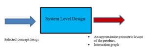
System Level Design
The next step of the design process is to generate a system level configuration of all components and layout the location of each one considering the interaction among them. Key issues related to the layout and types of components such as size, materials, human machine interface, relative location, and orientation need to be addressed at this stage. A final selected design concept is considered as an input and a developed geometric layout and an interaction graph will be the outputs of this stage. A typical system level design procedure can be represented as shown below.
Product Architecture
Product architecture relates the required functions of selected conceptual design to the corresponding physical arrangement of elements. Selected conceptual design can be divided into several physical building block (chunks). Each chunk can be a part, component, or subassembly. The chunks need to be arranged such that they can carry out the required functions. This arrangement of physical components is called module. There are two types of product architectures as follows:
- Integral architecture
- Modular architecture
Integral Architecture
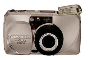
Integral architecture refers to an arrangement of components or modules that the required function(s) will be accomplished by one or a few components. In this configuration, each part or module performs multiple functions. Therefore, the “function sharing” happens once more than one component or module contribute to perform the required function(s). Generally speaking, integral architecture make components and modules more complex in terms of their shapes and configuration. Thus, this pproduct architecture generally improve the performance of design as the interactions between components/modules are reduced significantly. A typical camera is an example of integral architecture as shown below.
Modular Architecture
In a modular architecture, a set of components (i.e. chanks) implement the required function(s) completely. The interaction between chanks is well structured and defined. Using a modular architecture in product design and development makes easer to apply the reusability among of a group of product family. Besides, a modular architecture provides more effective way to design a product collaboratively as each design team focuses on designing and developing each module with well-defined interaction with adjacent modules. A typical Swiss army knife is a good representative of modular architecture as shown below.

Geometric Layout
Creating a geometric layout of the selected concept is the first step toward creating an assembly drawing. This is where the design team generates the shape and overall layout of the components, chunks, and modules and defines the interaction among them. In most cases, it is also possible to establish overall dimensions of the components, chunks, and modules. One should notice that the exact shapes, sizes and tolerances will be developed later in detail design phase. The geometric layout represents the geometrical location and orientation of each component. The process of generating a geometric layout is carried out in three steps as follows:
- Generate a pre-liminary geometric layout of the selected concept. At this step, a rough estimation of shape, size and location of each chunk will be determined.
- Identify the interaction among the components and generate an interaction graph illustrating those interactions. Two types of interactions between chunks are addressed including: (i) fundamental interactions representing those interactions resulting between chunks due to their physical connections; and (ii) incidental interactions representing those interaction resulting from the functions of other chunks and not directly neighbouring chunks. Examples of incidental interactions can be RF interference, thermal distortion, and vibrations.
- Design and develop each module/chunk of the product.
- Generate a detailed geometric layout.
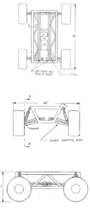
Examples of both pre-liminary and detailed geometric layouts are shown below.

An example of a preliminary geometric layout developed for a mobile robot

An example of a detailed geometric layout developed for a mobile robot.
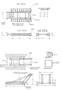
Examples of detailed geometric layouts developed for a mobile robot
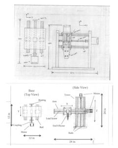
An example of a detailed geometric layout developed for a 3D cartesian robot
