3 Chapter 2.1 – Dense Point Cloud
Overview
Following the creation of a sparse 3D point cloud (i.e. tie points), the steps below outline the creation of dense 3D point cloud and the means of filtering out spurious points. The steps below will teach you how to generate tie points that form the basis for the dense point cloud.
Region of Interest
Rotate the tie points from a map view to a profile view using the red line on the trackball.
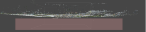
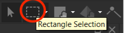
Using the Rectangle Selection tool (see below), click and drag a rectangle surrounding any outlying point below the surface and press Delete to remove them.
Press 0 (zero) to rotate the tie points back into map view. Adjusting the region of interest helps to speed up processing by excluding points outside the area of interest which are often characterized by lower redundancy observations.
Right-click the Move Region tool to drop down the menu including Transform Region, Resize Region and Reset Region…,
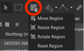
Select the appropriate tool to adjust the Region of Interest (ROI) to something similar as shown below.

Dense Cloud
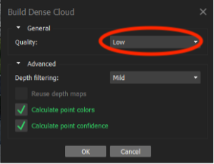
From the Workflow menu, select Build Dense Cloud, set the parameters as shown below and click OK. This step may take up to 60 minutes.
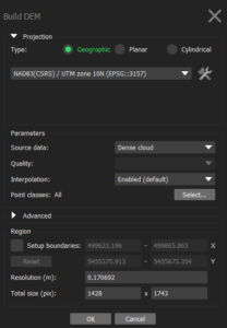
Build DEM
Build the digital surface model by going into the Workflow menu, selecting Build DEM…. Accept the default parameters and Click OK.
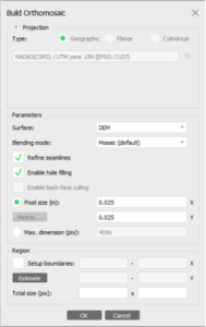
Build Orthomosaic
Build the orthomosaic by going into the Workflow menu, selecting Build Orthomosaic…, Adjust the parameters according to the screenshot below and Click OK.
Open the Orthomosaic and select Show Seamlines to see the pattern of automatically generated seamlines.