Chapter 1 – Locating and Measuring Physical Site Qualities
Eric Saczuk
Tools and Techniques
Overview of Digital Technologies and their Applications
Remotely Piloted Aircraft Systems or RPAS (aka drones) are rapidly becoming indispensable tools across many diverse sectors and industries. Their utility in construction, infrastructure inspection, natural resource management and mapping, delivery and of course cinematography is already well established. New applications in wildlife management, climate change research and aircraft inspections are now being explored.
The main benefits of drones as a new tool include accessibility, reduced cost, quick turn-around, high resolution data and improved safety. As the aircraft and related equipment become more reliable and capable, so does their utility and commercial acceptance. Of course, along with any benefits, the main barriers and challenges also need to be considered. These include relatively short battery life (~25min), lack of a reliable detect and avoid (DAA) system to automatically deconflict airspace with piloted aircraft, weather limitations, in particular precipitation, winds, visibility, and temperature and limited practical range over radio frequencies.
Nevertheless, every economic prediction shows a near exponential growth curve of the drone industry in the next five to 15 years with the industry being valued at over $25 billion US by 2030. With this kind of potential and the “cool” factor of the technology itself, it’s hard not be excited about the potential permeability of drones in many aspects of everyday life.
Detailed Site Data Acquisition and Interpretation
The process of successfully capturing drone-based data includes the following important steps, each of which involves a whole sequence of procedures which are beyond the scope of this manual:
- Airworthiness is the assurance that the aircraft is safe to fly for the intended mission
- Payload/sensor selection appropriate for the required data and mission
- Mission planning during which the important factors related directly to mission success are identified and appropriately incorporated including airspace, permissions and authorizations and aircraft flight parameters
- Site survey takes into account all of the aspects of ensuring that the selected site is safe to fly at and that the ground control plan, weather checks, airspace coordination and logistics have been completed
During data capture, the drone is most likely flying a pre-programmed flight path using waypoints based on a polygon outline of the area of interest. Almost always, the aircraft will maintain a constant altitude, though in some cases in can also follow the terrain at a predefined flying height. The most common flight path is a series of parallel flight lines spaced accordingly to allow for 70% to 90% of forward and side overlap between images or data points (as in the case of LiDAR). Once the mission is completed, or the battery is depleted, the drone will return to the take-off location. If the mission is to be continued, batteries are swapped, and the aircraft resumes where it left off.
I always like to say that data capture should be as boring as possible which means that mission planning was done correctly, and nothing is going wrong. The pilot still needs to remain alert, monitoring the payload function, telemetry including altitude, number of satellites, C2 and video link strength, battery levels, and flight mode as well ensuring that visual line of sight is maintained throughout the flight. As you might guess, that’s a lot to pay attention to and during more complex missions, a visual observer (VO) is employed to help keep track of the drone in the airspace.
Data Acquisition using remotely piloted aircraft systems (RPAS)
Remotely Piloted Aircraft Systems or RPAS (aka drones) are rapidly becoming indispensable tools across many diverse sectors and industries. Their utility in construction, infrastructure inspection, natural resource management and mapping, delivery and of course cinematography is already well established. New applications in wildlife management, climate change research and aircraft inspections are now being explored.
The main benefits of drones as a new tool include accessibility, reduced cost, quick turn-around, high resolution data and improved safety. As the aircraft and related equipment become more reliable and capable, so does their utility and commercial acceptance. Of course, along with any benefits, the main barriers and challenges also need to be considered. These include relatively short battery life (~25min), lack of a reliable detect and avoid (DAA) system to automatically deconflict airspace with piloted aircraft, weather limitations, in particular precipitation, winds, visibility, and temperature and limited practical range over radio frequencies.
Nevertheless, every economic prediction shows a near exponential growth curve of the drone industry in the next five to 15 years with the industry being valued at over $25 billion US by 2030. With this kind of potential and the “cool” factor of the technology itself, it’s hard not be excited about the potential permeability of drones in many aspects of everyday life.
Safety Aspects of operating RPAS for the purpose of data acquisition
A successful mission is conducted safely and meets the intended objectives. To help ensure this, it is imperative that the pilot understands and abides by all aviation rules pertaining to drone operations in their specific region. This includes obtaining any required certifications and permissions from the aviation authority and/or landowners, knowing the local privacy, voyeurism, and trespassing laws, and making sure that the aircraft is registered as needed. For information about how to safely fly a drone in Canada, go here.
From the link above, you’ll note that pilots operating drones weighing between 250g and 25kg will need to register their aircraft and obtain either their Basic or Advanced RPAS Certification from Transport Canada. For heavier drones an additional special flight operations certificate or SFOC, is required. The main points to always remember when flying a drone, regardless of your certification level are:
- Always fly your drone lower than 400ft or 122m*
- Always maintain unaided visual line of sight with your drone*
- If your drone has the required safety assurance rating, you must always maintain a minimum lateral distance of at least 30m from bystanders with a Basic Certification
- With an Advanced Certification, you may fly within a lateral distance of 5m or even over people, depending on the safety assurance of the drone
- You must ALWAYS yield to piloted aircraft
- Wait a minimum of 12 hours after consuming alcohol before flying a drone and 28 days after consuming cannabis
- Know the environmental limitations of your drone (e.g. maximum wind resistance and operating temperature range) and never fly a drone outside of these parameters and the minimums as defined in Canadian Aviation Regulations Part IX
- Have readily available an emergency checklist and emergency phone numbers in case of an incident or accident
Carefully consider where you are planning to take-off and land and whether you have permission to operate from that spot. Once the drone is airborne, it falls under the jurisdiction of Transport Canada and therefore it is your responsibility to know what airspace you are flying in. One common misconception is that people own the airspace above their property. Very simply, this is not true. What you do have to remember is to not violate people’s right to privacy by flying low enough or close enough to houses that you could be deemed to be “spying” on them.
Overview of suitable equipment and camera characteristics
When examining a drone, it quickly becomes apparent that it is really a system of systems. The basic components common to nearly all drones include propulsion, payload, navigation, and communication. While nearly all drones have some means of propulsion (e.g. propellers or rotary wing) some are gliders or even balloons. Payload can be anything from a simple color camera or package to more complex systems such as multi-spectral cameras, Light Detection and Ranging (LiDAR) systems, magnetometers, or methane detectors. The navigation system often comprises of a global navigation satellite system (GNSS) receiver, magnetic compass, and an inertial measurement unit (IMU) which measures acceleration in six axes to help keep the aircraft very stable in the air. Additional navigation systems may include vision positioning cameras to keep the aircraft from drifting when the GPS signal is weak (e.g. indoors), barometric altimeters to more accurately measure altitude differences, infrared and ultrasonic distance measuring devices used to avoid collisions with objects, and antennas to receive real-time kinematic (RTK) signals from GPS base stations for improved positional accuracy. Finally, the command and control (C2) system allows the pilot to send commands to the aircraft via radio (900MHz or 2.4GHz frequencies) or cellular (4G, LTE, 5G) signals and allows the pilot to receive telemetry and video back to the hand controller or ground control station via radio (2.4 or 5.8GHz) or cellular. Tying these systems together is the autopilot computer which takes inputs and sends outputs to and from the various systems so that the drone can do what the pilot commands.
In addition to the components listed above, we need to consider the many external systems that drones rely on for proper operation. For instance, a drone needs to acquire at least six GNSS satellites in order to know where it is on earth and how to get to where the pilot commands it go. Without this external system, the utility of drones would be greatly diminished. In fact, large solar flares from the sun can cause disruptions in the reliability of GPS positioning solutions and need to be monitored before and during flight via the global geomagnetic activity (kp) index value. In each country, drones are regulated via the specific aviation regulatory body (e.g. Transport Canada) and the pilot needs to be aware of and adhere to all the rules where they are flying. Without battery charging systems, two-way and aviation radios, laptop computers running specific mission-planning software, and sometimes a small army of ground and air crew, many drone operations would never get off the ground. The key takeaway here is proper preparation of all the systems and considerations mentioned above goes a long way towards ensuring a successful drone mission.
Basics of image processing and overview of applications: dense 3D point cloud, 3D texturized model, digital surface model (DSM) and ortho-mosaic
Boring data capture hopefully leads to exciting data processing! This is where you get to see the fruits of your labour and generate some neat, high resolution, geo-spatial data layers. We’ll cover the steps necessary to produce a 3D model, orthomosaic map, digital surface model, digital terrain model and contours using photogrammetry.
Following a photogrammetric data acquisition flight, what you will have, are a LOT of overlapping photos. It is not uncommon to collect hundreds, thousands or even tens of thousands of photos during a single data capture mission. The first step in processing these photos is to load them into photogrammetric image processing software such as Agisoft Metashape Pro. The sample dataset for this can be found here.
Setting up Agisoft Metashape Pro
Download and install Agisoft Metashape from here and download the sample dataset. Once installed, follow the steps below.
- From the Start menu, find the Agisoft folder and launch Agisoft Metashape Professional.
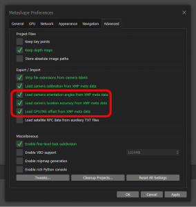
- From the Tools menu, select Preferences…, click the Advanced tab, adjust the settings as shown below then click Apply and OK.
- From the Workflow menu, select Add Photos. Navigate to where you downloaded the sample Images folder
- Click on one of the photos, select all (Ctrl A) and click Open.
- From the File menu, select Save As…, name the project your Name and save it.
- Note the two tabs near the bottom left of the screen, Workspace and Reference. Click on the Reference tab.
The positional accuracy of aerial photos (including those acquired by drones) can be expressed relatively (i.e. between two or more overlapping photos) and absolutely (i.e. with respect to an established real-world ground coordinate system such Lat/Long or UTM).
Relative accuracy measures how well the software managed to stitch adjacent, overlapping photos together given the inherent distortions related to pitch, roll and yaw of the aircraft/camera, lens distortions, atmospheric attenuation and earth curvature. This is typically expected to be less than two pixels. Ground pixel size, of course, depends on scale and ranges from several mm to tens of cm for most drone imagery.
Absolute accuracy is the positional agreement (both horizontal and vertical) between of a feature in the image expressed in a real-world coordinate system (e.g. Lat/Long or UTM) and the actual position of that same feature surveyed to a higher level of accuracy (e.g. RTK GPS or traverse).
The accuracy of consumer-grade GPS/GNSS receivers on-board many common drones (including, for example, the DJI Phantom 4 or Mavic 2) is around 2 to 5m. While this level of accuracy may be acceptable for certain applications (e.g. forestry or resource mapping), many situations will require accuracies an order or two higher (e.g. volume calculations or boundary surveys).
- In the Photos pane (bottom of the screen, see below), click on Change View and select Details.
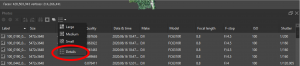
- Right-click under the Quality column, select Estimate Image Quality…, select All cameras and click OK. This will generate an index of the image quality for each photo.
Image quality ranges from 0 (lowest) to >1 (highest) and is based on criteria such as exposure, motion blur, focus and white balance. Sorting the images according to Quality allows you to check if any of the images are below about 0.7 as they shouldn’t be used in further processing.
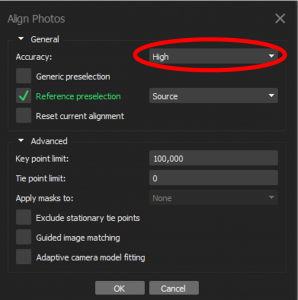
The next step in the automated photogrammetric process, is to align the photos relative to each other. This will generate the tie points which form the basis for the dense point cloud.
- From the Workflow menu, select Align Photos… and set the parameters as shown below and click OK. Note that higher Accuracy settings will result in much longer processing times. Ideally, since this step is quite fundamental, the Highest setting should be used when working with real datasets.
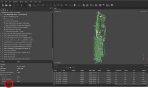
- Click on the Workspace tab then double-click on Tie Points and you should see a sparse point cloud showing approximately 400,000 between most of the 818 photos.
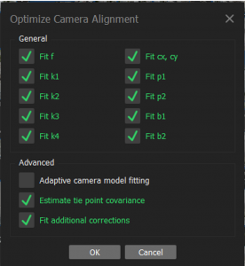
Now it’s time to perform a camera calibration to reduce the effects of the following distortions for each image; calibrated focal length (f), principal point of best symmetry (cx, cy), radial distortion (k1, k2 and k3), tangential distortions (b1 and b2) and decentering distortions (p1 and p2).
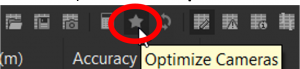
- Click on the Reference tab (bottom left) and select Optimize cameras from the menu.
- Set the parameters as shown below and click OK.
The next few steps are to filter spurious points, define the region of interest (ROI), create the dense cloud, DSM and DTM and true orthophoto.
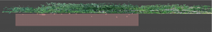
- Rotate the tie points from a map view to a profile view using the red line on the trackball or press 3 on the keyboard.
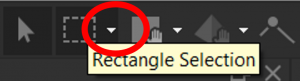
Using the Rectangle Selection tool, click and drag a rectangle surrounding any outlying point below the surface and press Delete to remove them.
- Press 0 (zero) to rotate the tie points back to map view.
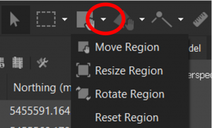
- Adjusting the region of interest helps to speed up processing by excluding points outside the area of interest which are often characterized by lower redundancy observations.
- Drop down the Move region tool menu and select the appropriate tool to adjust the ROI to something similar as shown below.
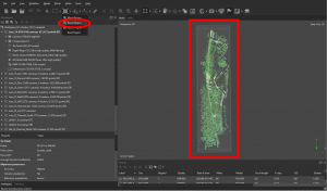
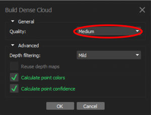
- From the Workflow menu, select Build Dense Cloud, set the parameters as shown below and click OK. This may take up to 60min.
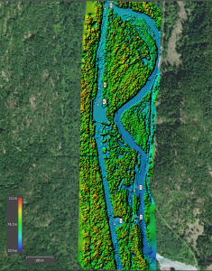
- Next, build the digital surface model by going into the Workflow menu, selecting Build DEM…, accepting the default parameters and clicking OK. The final result should look similar to the below.
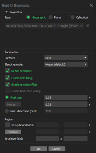
- Now, build the orthomosaic by going into the Workflow menu, selecting Build Orthomosaic…, adjusting the parameters as per the screenshot below and clicking OK.
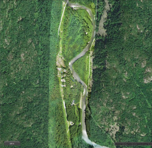
- The orthomosaic should look similar to the figure below.
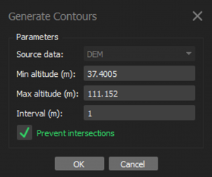
- Right-click on the DEM in the Workspace pane, select Create contours…, set the parameters as shown below and click OK.
The last steps are to export the orthomosaic in JPEG format.
- Right-click on Orthomosaic, select Export Orthomosaic then select Export JPEG/TIFF/PNG…
- Accept the default parameters and click Export…. In the Save As window, select JPEG from the Save as type dropdown menu, name the file your Name and click Save.
Media Attributions
- Metashape preferences window
- Screenshot 2021-12-01 194015
- Align photos settings
- Sparse point cloud
- Screenshot 2021-12-01 194135
- Screenshot 2021-12-01 194154
- Screenshot 2021-12-01 194212
- Screenshot 2021-12-01 194231
- Screenshot 2021-12-01 194252
- Screenshot 2021-12-01 194321
- Screenshot 2021-12-01 194343
- Screenshot 2021-12-01 194414
- Screenshot 2021-12-01 194449
- Screenshot 2021-12-01 194508
- Screenshot 2021-12-01 194530