7 Learning Objectives
After completing the learning tasks in this competency, you will be able to:
- Select valves
- Describe the gas valve trains for appliances rated at 400 MBH or less.
- Describe the purpose and operation of gas pressure regulators
- Describe the purpose and operation of automatic gas valves
Manual gas valves are incorporated into the piping system in different ways to provide a method of ensuring that the gas has been positively turned off to an area of the piping system or to a particular appliance. The gas fitter will need to select the correct valve for the job to be done. The gas codes will specify particular locations and applications that require the installations of manual gas valves.
For example, the CSA B149.1 Installation Code clearly requires that a readily accessible gas shut-off valve for each appliance be installed. This manual appliance shut-off valve is typically located just outside of the appliance, where it can be easily reached, to enable the gasfitter to isolate the appliance to perform any necessary repairs or service.
Types of Manual Gas Valves
Most gas shut-off applications will require the use of a manual valve that will fully open or close with a quarter-turn of the handle. Ball valves and lubricated plug valves are the most common, but eccentric types are also used on larger pipelines. Globe, butterfly, and needle types are also used for throttling applications.
Valve ratings
All gas valves must be used within their certified pressure and temperature rating range. The gas installation code recognizes a number of different certification organizations and standards for manual shut-off valves. The markings on the gas valve and or the manufactures specification can be checked to verify the intended purpose for the valve. The multiple approvals that are typically found on each valve can become confusing, as the manufacture attempts to mark all the associated certifications onto the valve body and or handle (Figure 1).
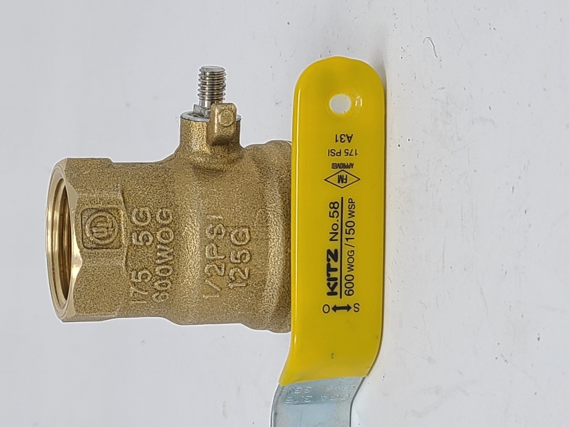
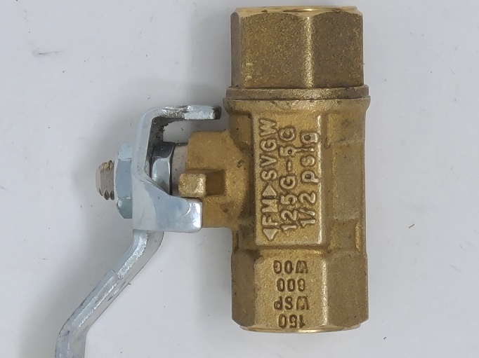
Figure 1 Valve markings
Common pressure class or rating markings that are found on gas valves include:
- WOG stands for Water, Oil and Gas and CWP stands for Cold Working Pressure. They both refer to the non-shock pressure rating for valves at an ambient temperature up to 380 C. Water is straightforward but the oil and gas parts are a little more complicated. “Gas” references air, nitrogen etc. but does not cover combustible gases. There are more specific approvals required for fuel gas applications.
- WSP stands for Working Steam Pressure and defines the pressure of steam in a system that a valve can be used in. The industry uses WSP for bronze ball valves because, as the temperature rises, the strength of the material decreases.
- G is for combustible gases, as not all valves are certified for use on fuel gas applications. Valves that are certified for combustible gas applications will have some or all of the following specific markings:
- ½ PSIG (or 1/2 G) – a lower pressure rating for gas valves generally used at a gas fired appliance.
- 5G – a higher pressure rating for gas valves generally used indoor and out in Canada on gas piping distribution systems.
- 125G – a USA gas pressure rating of 125PSIG for use in gas piping systems.
- CAN/CGA-3.16 – a Canadian gas pressure rating of 125 PSIG for outdoor use in gas piping systems
The most common certification organizations abbreviations that appear on valves to identify their rating are:
- UL – Underwriter’s Laboratories tests valves to 3 times the pressure rating stated on the valve body. These valves must pass UL’s test in order to have the UL logo on the valve body.
- CSA – Canadian Standards Association is another organization that tests valves to ensure they meet their standards. Even though this is a Canadian association, it does tests for both Canadian and US standards. A “C” or “US” may be found under their logo indicating which country’s standards the valve has been tested to. If both appear, the valve has been tested to the highest standard in both countries.
- CGA – Compressed Gas Association develops standards for the industrial, medical, and food gases industry
- <FM> – Factory Mutual Global, a US based insurance company, has approved the valve. They take an engineering approach to make sure the valve meets their high standards.
- UPC / cUPC – Uniform Plumbing Code (UPC) and Canadian Uniform Plumbing Code (cUPC) ensure that plumbing products are safe and sanitary.
- ANSI – American National Standards Institute tests valves to various standards.
Ball valves
The lever operated non-lubricated ball valve is the most common valve used for appliance shut-off. For residential and commercial applications, they are usually constructed of a brass (BRS) body with a chrome plated brass ball. Teflon seats and packing are most common but smaller sizes may use O-rings (Figure 2).
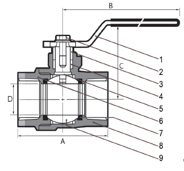
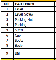
Figure 2 Cross section of lever operated ball valve
The ball has a hole drilled through its center. With the handle in the open position, (aligned with the valve) the hole is aligned with the connection openings in the valve body and flow is permitted. When the valve is closed both the handle and hole are positioned perpendicularly to the valve body and flow is stopped (Figure 3).
Figure 3 Manual ball valve operation
The valves are often constructed with a two-piece body in which the two threaded halves hold the ball and seats in place. Smaller valves may be of a one-piece body design, which use a retaining clip and washer to hold the ball and seats in place (Figure 4).
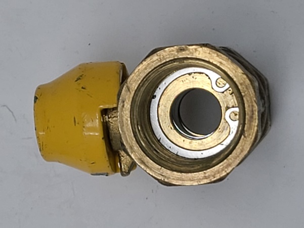
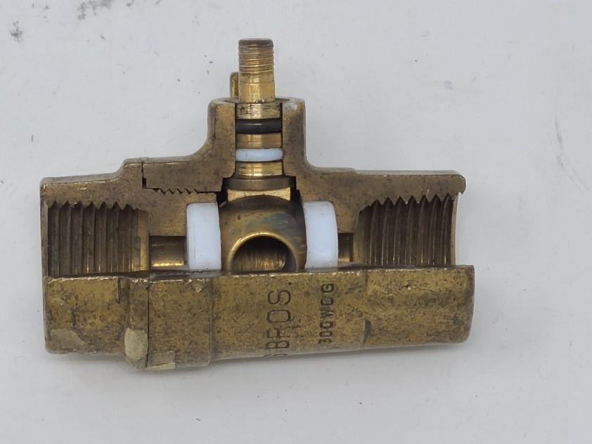
Figure 4 two-piece valve (left). One-piece valve (right)
The size of the hole or port in the ball may vary. A full port ball valve has the same internal hole size as the nominal pipe size connections. A reduced port ball valve, also known as a standard port ball valve, has an opening through the ball that is one pipe size smaller than the valve’s nominal pipe size connection (Figure 5).
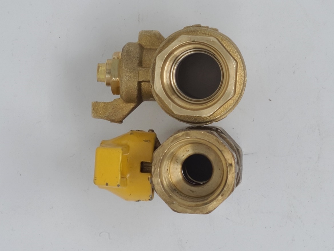
Figure 5 Reduced port (left). Full port (right)
Handle types
Ball valves are available with various handle styles and colours. Gas valve are available with different types of handle including steel, aluminum or wing handles (Figure 6). While gas valve handles are often coloured yellow, you will also find gas rated ball valves in other colours such as red, blue and green. Some handles are designed so they can be used to lock the valve position, by removing and reinstalling the handle so the notch holds the valve in the closed locked position.
End connections
Brass ball valves under NPS 2” are most commonly supplied with internal threads (FNPT) or male flared end connections, or a combination of both (Figure 6).
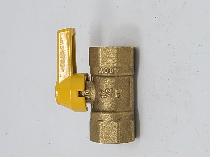
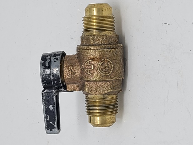
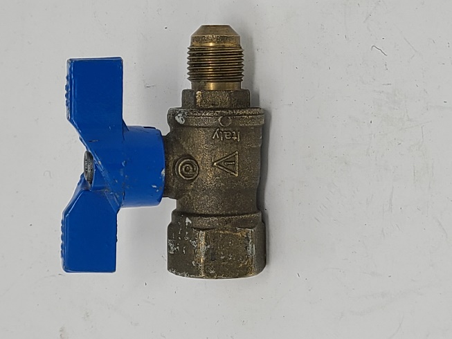
Figure 6 Ball valve end connections
Plug valves
Plug valves are another type of manual shut off used in gas systems. They also fully open or close with a quarter turn of the handle. They use a tapered, drilled “plug” as their isolating component instead of a ball. Brass spring loaded versions were used in the past for indoor, low pressure applications (Figure 7) but are no longer manufactured.
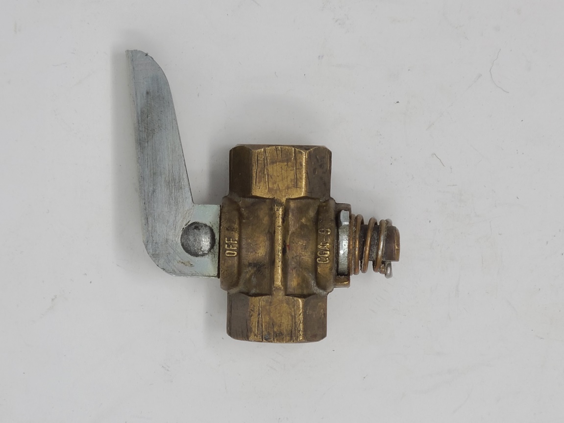
Figure 7 Spring loaded gas valve
The lubricated type of plug valve is approved for indoor or outdoor use and is common on exterior gas meter installations. It is often called a Luboseal™ gas valve after one of the most popular brand names. The tapered plug has O-rings at the top and bottom so that a film of lubricating sealant is maintained between the internal surfaces of the plug and matching body (Figure 8).
Lube port
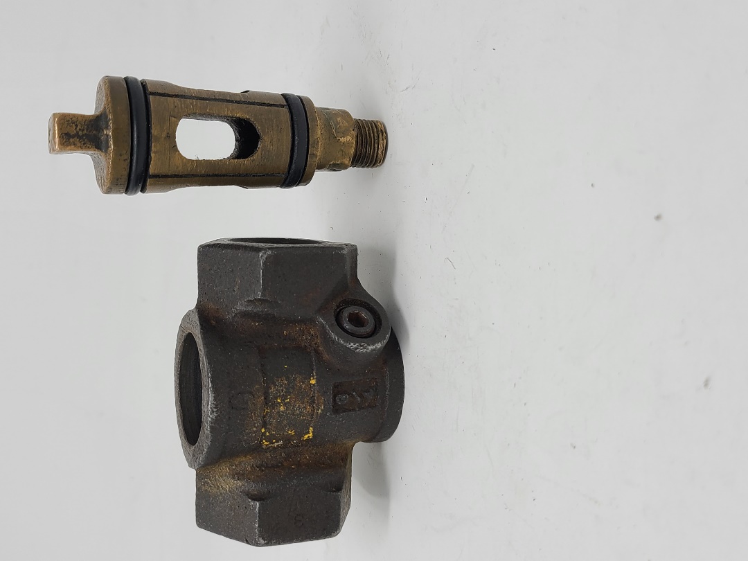
Figure 8 Lubricated plug valve
Lube portButton head grease fitting
The lubrication helps ensure a gas tight seal and provides easier turning of the plug in the body. Machined grooves and passages enable the valve to be relubricated and maintained with the valve in place and with no interruption of service. Lubricant is injected through a port located in the valve body (Figure 8) or top of the plug (Figure 9).
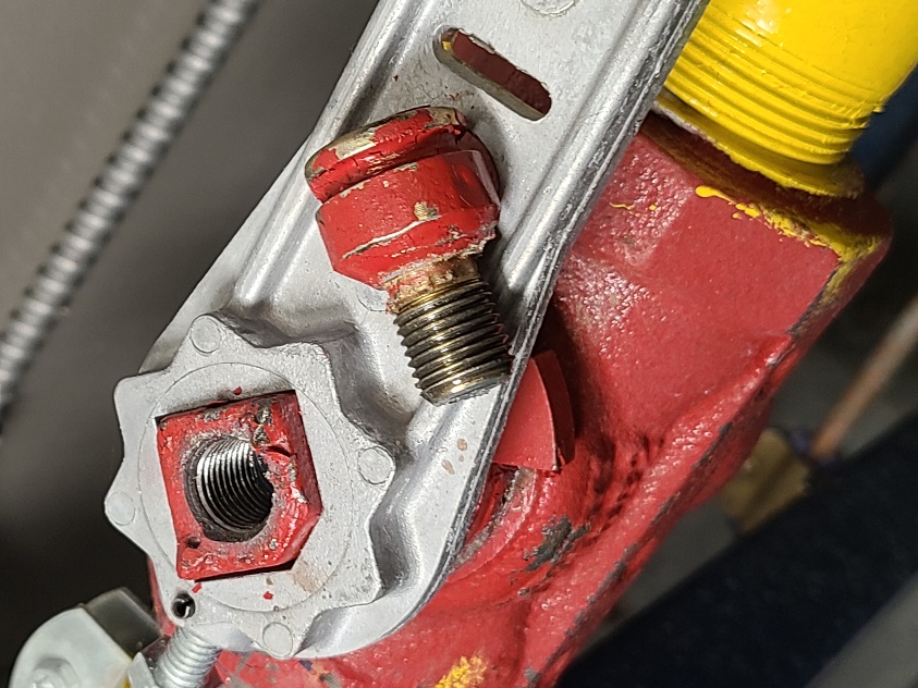
Figure 9 Stem fitting lube plug valve
Lubricated gas valves installed within the meter sets are maintained by the gas utility. Notice that the three gas valves shown in figure 10 are a locking type with the middle bypass valve locked in the closed position. The top red valve also has a dielectric insulated union outlet.
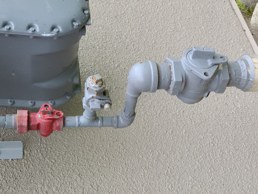
Figure 10 Luboseal™ gas valves on meter set supply
Throttling valves
There are other manual valves that are not used for positive shut-off on fuel gas systems. They are also known as firing rate valves or limiting orifice valves in certain applications (Figure 11). For example, butterfly, globe, and needle valves are used for burner flow adjustment, but must have an approved manual shut-off valve installed upstream.
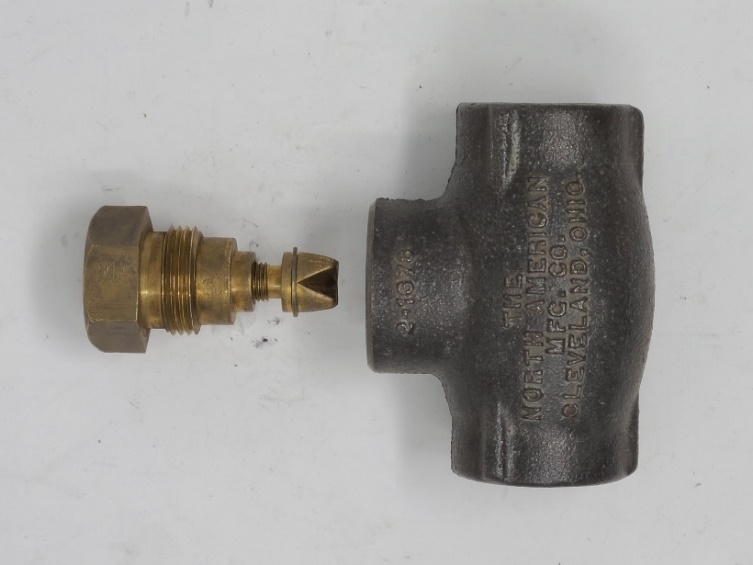
Figure 11 Globe style limiting orifice gas valve
Now complete B-1 LT1 Self-Test and check your answers.
The appliance shut-off valve is typically located just inside the appliance service cover, were it can be easily reached.
True
False
Most gas shut-off applications will require the use of a manual valve that will fully open or close with a quarter-turn of the handle
True
False
A valves Water, Oil and Gas (WOG) pressure rating includes the maximum approved pressure for use on fuel gas applications.
True
False
A threaded brass ball valve has the following markings: 600 WOG, 150 WSP,1/2 G, 5G, CGA 3.16. what is the maximum certified pressure rating for combustible gas applications?
½ psig
5 psig
125 psig
600 psig
A standard port ball valve has an opening through the ball that is one pipe size smaller than the valves’ connection size.
True
False
A Luboseal™ gas valve must be shut off in order to be relubricated.
True
False
Butterfly, globe and needle valves are commonly used as appliance shut-off valve.
True
False
What is the colour of the valve handles on approved gas valves?
Red
Blue
Yellow
Any of the choices
LEARNING TASK 2
The series of controls and components from the appliance main shut-off valve to the appliance burner is called the valve-train or manifold assembly. The components of the valve train are used to manually and automatically start, stop and regulate the gas flow to the appliance. On larger gas appliances, generally over 400 MBH, the valve train components downstream of the manual shut-off valve (Figure 12) will be field assembled as they are not an integral part of the appliance. For these installations the requirement for valve train components and their assembly are identified in the separate CSA B149.3 gas code.
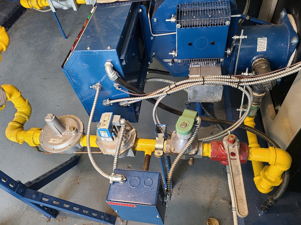
Figure 12 Field assembled valve train
For installations under 400MBH the valve train assembly is typically supplied and preassembled as part of the appliance. Although manufactures appliance valve trains will vary in how they are assembled, they will all have the components shown in Figure 13 in one form or another. This diagram is used as in introduction because it shows all of the components as separate parts, whereas on modern appliance many of these components are combined into one valve. body.
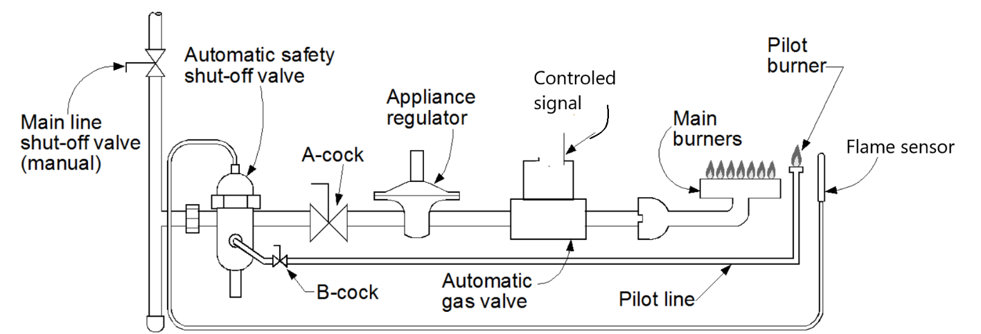
Figure 13 Valve train assembly
The valve train components from the manual shut-off valve will include:
- Automatic safety shut-off valve; will turn off all the gas to the appliance in the event of burner failure. If the automatic safety shut-off valve stops the flow of gas to both the main burner and the pilot burner it is referred to as 100% safe.
- B-cock; can be a ball valve but, is usually a needle-type valve included within a combination valve body. It is used to isolate as well as throttle the volume of flow to the pilot burner assembly in order to adjust the pilot flame.
- A-Cock; a manual shut-off valve that is used to isolate the components downstream to enable servicing while still allowing gas to flow to the pilot. It does not regulate either flow or pressure, just opens and closes the gas line.
- Appliance regulator; maintains a constant gas pressure to the burner(s) over a sometimes fluctuating gas inlet pressure and a possible modulating burner gas flow. This assures a constant, even flame at the main burners. Regulators will be looked at in greater detail in Learning Task 3
- Automatic gas valve; a valve normally energized by a 24-volt alternating current (AC), but may be line voltage (120 V) or millivoltage (thousandths of a volt). It is usually wired in series with a sensing control (thermostat, aquastat, or pressuretrol) which automatically activates the appliance as needed. It can also be a non -electric valve activated by a mechanical heat sensing controller.
Now complete B-1 LT2 Self-Test and check your answers.
Where is the appliance regulator located in relation to the automatic gas valve?
On the pilot line
Upstream of the automatic gas valve
Downstream of the automatic gas valve
Upstream of the appliance manual shut-off valve
The A-Cock is a manual shut-off valve used to adjust the pilot burner.
True
False
Which gas code contains the requirements for the field assembly of gas valve trains?
CSA B149.1
CSA B149.2
CSA B149.3
CSA B149.5
What is the name of the systems were the automatic safety shut-off valve stops the gas flow to both the main burner and the pilot burner?
80% safe
Wild pilot
100% safe
Non-100% safe
An electric automatic gas valve is normally operated by 120 VAC.
True
False
LEARNING TASK 3
Pressures throughout the various gas piping systems varies greatly to accommodate the different system requirements and limitations. For example, the natural gas customer supply mains or propane storage containers will have high pressure to increase their volume capacity. Whereas the maximum allowable inlet pressure for gas appliances is typically only ½ psig, Pressure regulators are used throughout gas piping systems to maintain a desired reduced outlet downstream pressure while providing the required gas flow to satisfy the demand. Regulators are self-contained, self-operated control devices which use energy from the system to operate.
Other the following terms may vary in their usage for this textbook we will use the following definitions:
Category – The name associated with regulators used to serve a specific purpose and or location
Classification or Class – a term used to express pressure or volume limitations that may exit within a category.
Type – a term used to identify various physical styles and designs. There are many regulator types that exist within a category to achieve different performance characteristics.
SCFH – capacity; means standard cubic feet per hour of a gas at temperature of 70° F and a pressure of 14.7 PSIA.
Servo or Pilot – a mechanism set in operation by another mechanism
