11 Regulator Operation
Although direct -operated regulators are available in many different styles and designs their basic operating principles and the same. All regulators have three basic operating elements or components that are used to control flow rates as well as pressure shown in Figure 21.
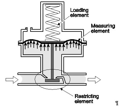
Figure 21 Operating elements
Restricting element
The restricting element consists of the valve body, orifice, valve plug, and stem (Figure 22). Together they control the amount of flow through the orifice opening. As the stem is moved upward, the valve plug moves toward the orifice, restricting flow. Flow through the orifice is increased by moving the stem downward, away from the orifice.
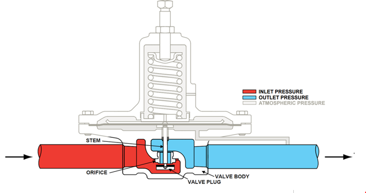
Figure 22 Restricting element
Measuring element
The measuring element provides feedback to the regulator on whether the flow demand is being matched The measuring element is usually a diaphragm that senses the changes in the downstream pressure (Figure 23). Made of neoprene, it is extremely flexible and usually is supported by a metal plate that allows downstream pressure to act upon the diaphragm evenly. The plate is connected to the valve stem so it will modulate the valve plug position based on the downstream pressure it senses through the control line or internal port.
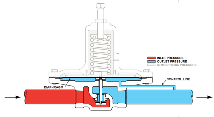
Figure 23 Measuring element
Loading element
On modern regulator the loading element is a spring used to counter balance the force created by the downstream pressure on the underside of the diaphragm (Figure 24). The springs opening force changed with the adjusting screw. This will adjust the desired outlet pressure, known as the regulators setpoint.
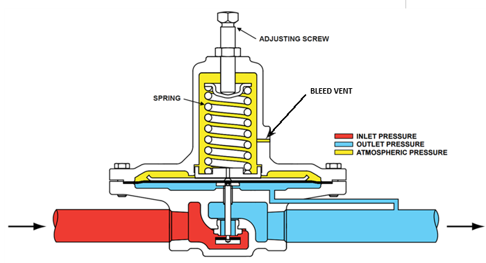
Figure 24 Loading element
Principles of operation
The help understand the operation and troubleshooting of regulators it is worth noting that an uninstalled direct operated regulator is in the normally open (NO) position, as the closing force requires downstream gas pressure.
We will begin the operating sequence as if it is a newly installed gas piping system that is just being pressurized.
- As the systems fills gas will flow through the open valve, the gas pressure downstream of the regulator will begin to increase, filling the chamber below the diaphragm causing it to move upward against the spring tension. Air exiting the upper chamber through the bleed vent allows the diaphragm to move freely. The upward movement of the diaphragm closes the valve. The amount of downstream pressure necessary to close the valve is directly related to the force exerted by the spring on top of the diaphragm. This is called the set point.
- When an appliance starts, gas pressure under the diaphragm decreases allowing the spring to push the diaphragm downward opening the valve. Air entering the bleed vent allows the diaphragm to move freely.
- The diaphragm and valve stabilize when the force under the diaphragm equals the force exerted by the spring. At this point the regulator has found its point of equilibrium and the flow rate and pressure downstream match that which is required by the system.
- If additional appliances start or an increase in firing rate occurs, the diaphragm moves further downward and the valve stabilizes in a new position in relation to the orifice, allowing more gas flow at the same pressure setpoint.
- If gas demand decreases or stops, the diaphragm moves upward and the valve stabilizes in a new position in relation to the orifice, allowing less gas flow at the same pressure. Air entering and exiting the vent allows the diaphragm to move freely.
Adjusting setpoint
Regulators can be adjusted to change the outlet pressure setpoint within certain limits of the spring range. The desired outlet pressure can be changed by adjusting the screw in its housing (Figure 25) to increase or decrease the force exerted by the spring on the flexible diaphragm.
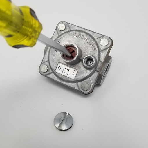
Figure 25 Turning adjusting screw
Use the following procedure to change the setpoint:
Turn off the gas.
Install the pressure test equipment to sense downstream pressure. Some regulators will have threaded pressure plugs on the valve body to connect (Figure 26). But many will not have gauge connections and you will need to find an appropriate connection point.
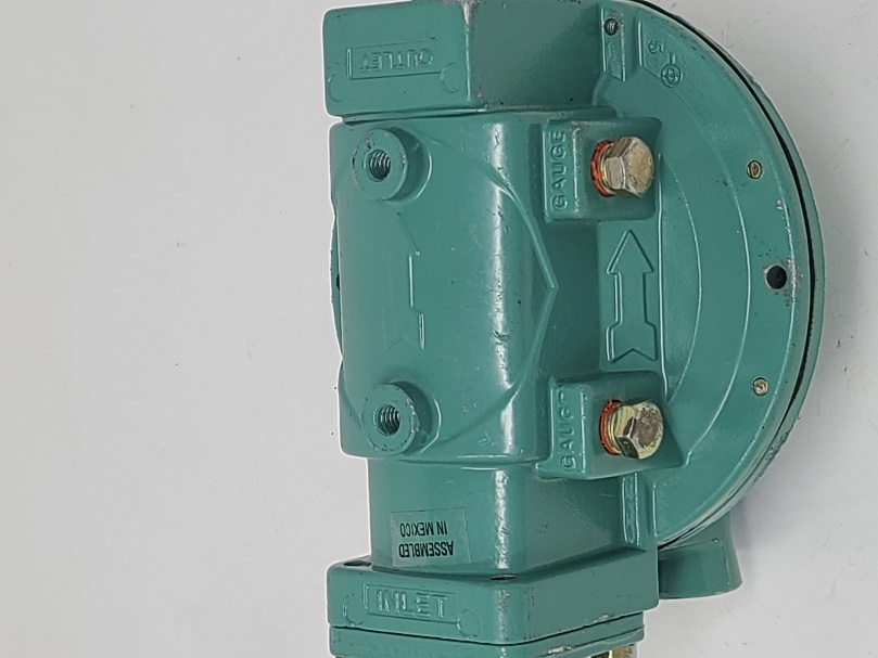
Figure 26 Regulators with pressure test ports
Remove the regulator adjusting screw cap.
Turn on the gas.
Turn the equipment on, allowing the gas to flow.
Look at the pressure and make the appropriate adjustment. To increase the outlet pressure, turn the adjusting screw clockwise to increase the tension is applied to the spring. For a lower outlet pressure, the adjusting screw is turned counter-clockwise to lessen the tension on the spring.
Replace the cap.
Shut off the gas.
Remove the test equipment.
Properly plug any test points.
Turn on the gas
Leak test the test points.
Check the operation of the appliances or burners downstream of the regulator to ensure that they are in safe operating condition.
