Chapter II: Mineral Processing
2. Size Reduction
Size Reduction Mechanisms
Industrial size reduction equipment utilizes three mechanisms illustrated in Figure 2.1 (below):
- Abrasion
- Slow compression
- Fast compression (impact)
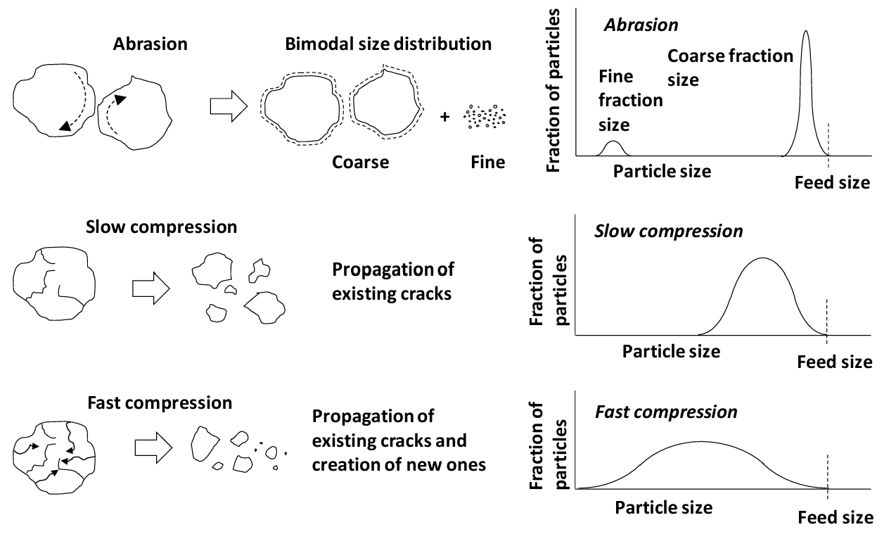
A purely abrasive process induces high shear at the rock surface. Fine particles are produced and a larger core particle remains. This results in a bimodal fine/coarse size distribution. In slow compression gradual increase in stress propagates existing cracks. A moderately wide range size distribution product results. Under fast compression compressive stress waves propagate through the rock. These are reflected back from the surfaces as high stress tensile waves. Existing cracks get propagated and new cracks are created. Shattering occurs. The size distribution may be quite broad with quite fine material being produced, in part. Factors that influence rock failure are described in Table 2.1 (below).
| Table 2.1 - Factors affecting rock fracture. | |
|---|---|
| Nature of applied stress | Compressive, tensile or shear |
| Method of application | Strain rate and whether the rock is constrained or not |
| Particle geometry | Size and shape |
| Microstructure | Proportion of each mineral, distribution of mineral grains, physical properties of the minerals and pre-existing cracks/defects |
Particle geometry affects how stresses are concentrated and distributed. Microstructure influences how readily the mineral grains themselves fracture.
Two Types of Size Reduction
There are two classes of size reduction (or comminution). The first is crushing. This reduces large rocks to smaller rocks (roughly centimeter scale at the smallest). The second class is grinding. This produces fine material (roughly <100 μm). Crushing necessarily occurs first.
Characteristics of crushing are:
- The output maximum particle size is determined by the machine discharge opening dimensions.
- The maximum feed size to a mill is determine by the machine opening dimensions.
Grinding characteristics are:
- The product particle size (a distribution) depends on residence time in the mill, not machine discharge opening dimensions.
- Related to the first point, output particle size is roughly proportional to the input particle size.
Crushing Machines
Traditional types of crushing machines include:
- Jaw crushers
- Gyratory crushers
- Roll crushers
- Impact crushers (hammer mills)
The first two are very common in mineral processing. Roll crushers are beginning to show up in mineral processing; they tend to have higher capital costs but lower operating costs.
Jaw Crushers
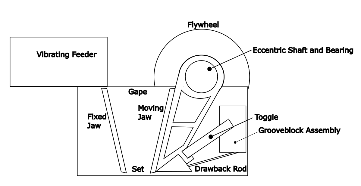
An illustration of a jaw crusher is shown in Figure 2.2. Ore material feeds by gravity into the top of the machine. A hinged plate moves back and forth and there is fixed plate against which the hinged plates closes. During the opening part of the cycle the machine receives rock. The maximum opening dimensions (moveable plate fully retracted) is called the gape and determines the maximum feed rock size. During the closing stroke the rock is crushed. The hinged plate, like 9 a big jawbone "bites" on the rock, hence the name jaw crusher. Crushing is by slow compression as the jaw closes. Rock is crushed by compression against other rocks and against the surfaces of the machine. Rock small enough to pass the discharge opening at the bottom (the set) falls out under gravity. This is what determines the maximum output size.
Jaw crushers only do crushing work on the closing part of the cycle. They can accept rocks up to 3 m in length, which makes them well suited to size reduction of the largest mined rocks. They have high energy consumption. Prescreening of the feed rock to remove suitably small material in advance can lower energy consumption and improve throughput; rock already the right size does not have to waste machine capacity by being passed through it. Power draw varies through the open-close cycle, being higher during the closing portion. A large flywheel helps to even out the power draw. Gyratory crushers tend to be short height, large footprint machines. This can make them well suited to use in a mine.
Gyratory Crushers
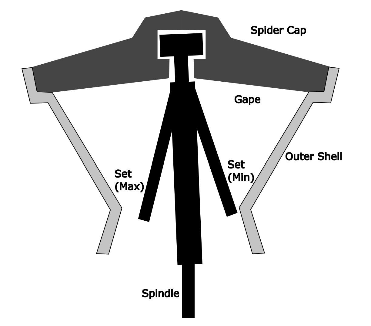
Gyratory crushers (Figure 2.3) have a conical outer wall and a large spindle suspended from a bearing supported across the top of the mount of the crusher. Because of this, their maximum feed rock size is smaller than a jaw crusher by a bit more than half. The spindle oscillates from below in a circular motion. This means that the crusher is continuously crushing as the spindle goes round and round. Hence a gyratory crusher has greater throughput that a jaw crusher; the latter crushes only half of the time it is operating - on the closing stroke. Gyratory crushers work by slow compression along with some shear. They are preferable to jaw crushers where their implementation is practical, due to their higher throughput. They also have modestly lower power consumption. Gyratory crushers have smaller footprint, but they tend to be tall. Their height can make them less suitable for crushing in a mine. Jaw and gyratory crushers are primary crushing machines. They are used to treat as-mined ore.
Cone Crushers
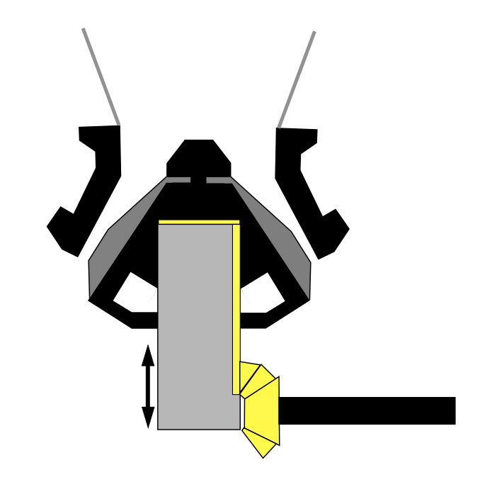
Cone crushers are modified gyratory crushers (See Figure 2.4). They are smaller. The spindle is supported from the bottom, leaving more space in the mouth to accept feed rock, which improves throughput. They have extended crushing surface area where the shell and spindle are closer to parallel. This allows for enhanced surface area for crushing and more uniform output product size. (However, all size reduction machines result in a distribution of output particle sizes.) The spindle rotates much more rapidly than in a gyratory crusher, causing fracture mainly by fast compression. Cone crushers may be used after primary crushers for further size reduction. However, in modern size reduction circuits the trend is to lower the number of machines involved for obvious reasons. There are other types of crushing machines as well that are not dealt with here.
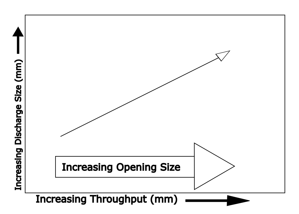
Throughput or capacity of a crusher is a function of the input feed size and the output or discharge size. This is illustrated in Figure 2.4. As throughput increases the discharge size also necessarily increases. This is because increasing throughput means less time in the crusher and therefore less time to effect size reduction. A family of curves is shown for the two types of primary crushers. The larger the opening size of the machine, the greater the throughput.
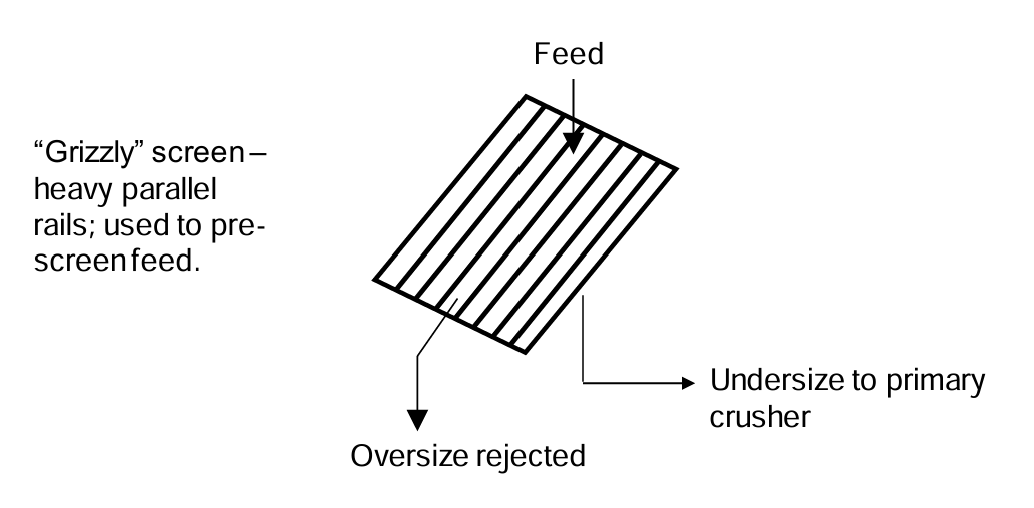
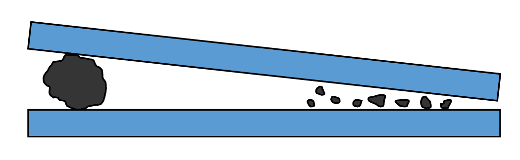
Oversize material too big to pass into a primary crushing machine can hinder continuous operation. A screen called a "grizzly" can be used ahead of the feed into the crusher to remove oversize rock. A grizzly consists of heavy parallel steel rails on an incline. Undersize material passes through and feeds to the crusher. Oversize material rolls off the top surface and is rejected. A schematic illustration is presented in Figure 2.5 (below).
Roll Crushers
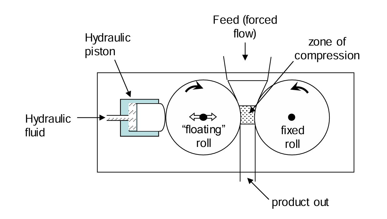
Roll crushers are well established crushing machines, and they have begun to make a significant appearance in extractive metallurgy. See Figure 2.7 for a schematic illustration. In a roll crusher there are two side-by-side rolls. One is fixed and the other can move somewhat, side to side, limited by hydraulic pistons, for example. This maintains a constant pressure on the feed rock. Pressures of 130-160 bars (1 bar = 0.987 atm = 100 kPa) are used. Ore is fed between the rolls. The maximum output size is determined by the gap between the rolls (the minimum gap, which can vary somewhat due to the moveable roll). They impose a high degree of shear on the rocks. Rolls may be smooth or toothed. They are well suited to weaker rock feeds. Rolls may be >2 m in diameter. In some applications roll crushers have replaced cone crushers.
Grinding Machines
Grinding further reduces size to fine material (about 100 m or less). Classical grinding machines are also called tumbling machines. In crushing a part of the machine moves against a fixed surface. In tumbling mills the entire machine is rotated. The ore charge is ground and there is usually a grinding medium added as well. This consists of suitably shaped, dense material (e.g. steel or ceramics) that aid in size reduction. Again, it is not the machine opening size that determines the output product size distribution (as in crushing mills), but rather the residence time of the charge in the mill.
Rod Mills
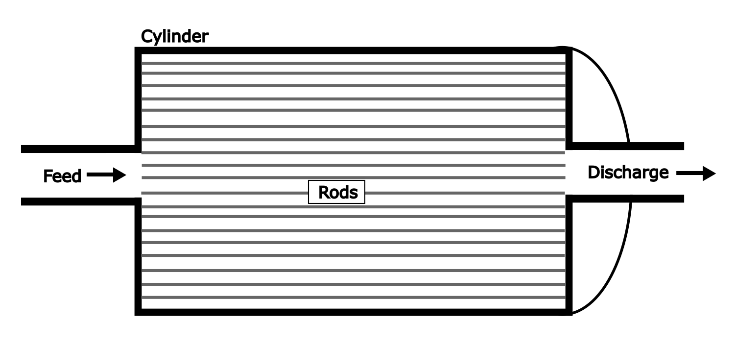
Rod mills (Figure 2.8) are a type of tumbling mill. Crushed ore is fed into the mill. Long cylindrical steel rods are used as a grinding medium. Rod mills are long and narrow. The drum is rotated and the ore charge plus rods roll around inside the mill. The rods move freely inside the mill. Size reduction occurs by a combination of slow compression, fast compression (impact) and abrasion. It is common to carry the ore material with water (wet grinding). Because the steel rods are long they remain parallel. Large particles tend to be broken preferentially over smaller ones. A large particle will "feel" the force of steel rods more due to the greater separation created between the rods as illustrated in Figure 2.9. As a result rod mill product tends to have a somewhat narrower size distribution and can produce lesser amounts of very fine material compared to a ball mill (below). Rod mills are good for grinding coarse material. Rod mill product may be as small as about 70 m. As can be seen from Figure 2.8 (A), the discharge opening is much larger than the particle size. Rod mills may be used ahead of ball mills.
Rods are made of high carbon steel. This makes them hard and resistant to bending. It also makes them brittle, so rods can break. But, that's preferable to a tangled mass of bent rods that can't move past each other. Energy consumption is high, in part due to the ever increasing amount of surface area per unit mass of ore as particle size decreases (generating surface area takes energy). But it is also high because the entire mill plus contents have to be turned.
Ball Mills
Ball mills use steel or ceramic spheres as grinding media. Ball mills are also tumbling mills; the whole mill plus contents is rotated (Figures 2.10 -2.12). Traditionally ball mills were used to produce the finest particle sizes, though other types of mills can now produce finer material. Ball mills employ wet (ore-water slurry) or dry grinding. The grinding media need to be small enough to maximize surface area and thereby, contact with the ore particles. But they also need to be large enough to provide the mass and impact forces required for grinding. Ball mills work by fast compression and abrasion mechanisms.
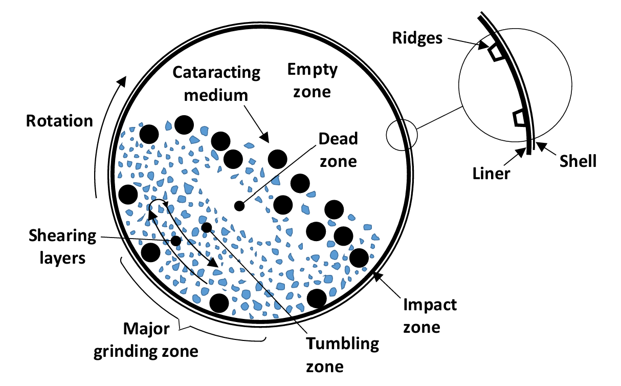
Control of the ball mill rotation rate is crucial. If it is rotated too quickly the balls and ore get pinned against the wall and grinding efficiency becomes poor. But if the rotation rate is too slow then the balls and ore charge just gently roll around inside the mill, and grinding efficiency again is poor. What is needed is for a rotation speed such that the balls are carried part way up the wall of the mill and then flung under gravity to impact the opposite wall. Ore particles need to be able to tumble. For a given particle mass (or size given the density) there is a critical rotation velocity at which such a particle is just pinned to the wall. Ball mills are typically operated at 65-80% of this critical speed. Ore is carried up the wall of the mill as shown in Figure 2.13. Some also moves down in the opposite direction (shearing flow occurs). Most of the grinding occurs in this region. Impact grinding occurs in the impact zone. Ball mills are operated at 30-50% of their full volume. There is more complexity than is shown in the diagram.
The rate of breakage of a given size of particles (i) in a grinding mill is directly proportional to the mass of those particles (Mi) in the mill (a first order process):
\[ \frac{dM_i}{dt} = -kM_i \tag{1}\]
The rate constant k is related to a number of factors, including:
- Mill diameter.
- Size of the grinding media.
- Shape of the grinding media (spheres, rods, cubes, etc.).
- Density of the grinding media (higher density increases the rate, up to a point).
- Amount of material in the mill (k peaks beyond some amount).
- Fraction of grinding media in the charge (k increases up to a point as fraction of grinding media increases).
- Slurry viscosity (decreased proportion of water increases viscosity; decreases k).
Autogenous (AG) and Semi-autogenous (SAG) Mills
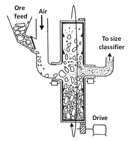
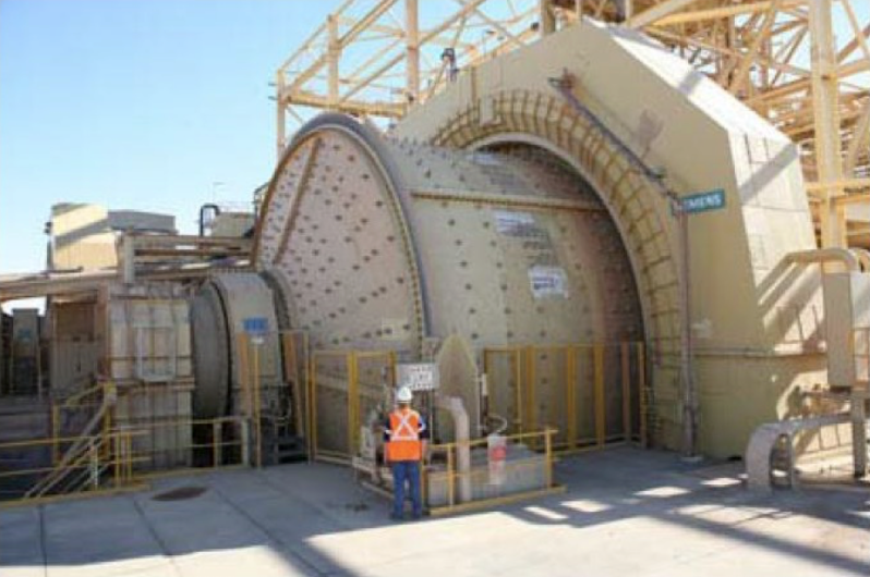
Autogenous mills were devised to try to replace more than one mill with a single mill. See Figure 2.12. They are another version of a tumbling mill. The idea was to use the rocks themselves as the grinding medium. Since rock density is typically significantly less (e.g. about 2.4 g/cm3 for silica; about 5.3 g/cm3 for hematite) than that of steel (about 8 g/cm3), the diameter of an AG mill needs to be greater than that of, say, a ball mill to obtain the same impact forces. So AG mills have large diameters and short lengths (diameter/length > 1). Semi-autogenous (SAG) mills (Figure 2.13) are like AG mills, but they also have added grinding media to enhance grinding. AG and SAG mills can be more than 40 feet (>12 m) in diameter. The main mechanisms of grinding are impact (fast compression) and abrasion. To allow enough space for impact 25-30% of the mill volume is occupied by ore. In SAG mills the grinding media may occupy 2-20% of the mill volume.
These mills are often used to accept primary crusher product and reduce it to a size suitable for feeding into a ball mill. AG mills are suitable when the ore (or some fraction thereof) is hard enough to act as its own grinding medium. However, this is not commonly the case. SAG mills are much more commonly used. With increased amount of added grinding media impact breakage becomes increasingly predominant. As a result SAG mills will produce a coarser product than AG mills. AG or SAG mills can replace cone crushers plus rod mills with a single machine. Sometimes a SAG mill product does not need to be reduced further in size and can go straight to a mineral separation process. In other cases the mined ore can be fed directly into a SAG mill, eliminating the need for a primary crusher. SAG mills can grind a broad range of ore types. They can be designed to have large capacities (throughput) and can replace two or more other, conventional size reduction machines. Their operating costs can be lower than conventional machines. Hence they are common in modern mineral processing operations.
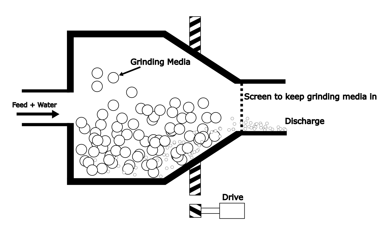
Stirred and Tower Mills
These mills are used to produce achieve fine grinding, smaller than can be achieved with a ball mill. They can produce particles sizes of <20 μm and to as small as 1 μm. They employ grinding media, but much smaller than in a ball mill (10 mm to about 1 mm). Most of the mill volume is filled with the ore charge and the grinding media. The mixture is stirred by means of an impeller or a vertically mounted, wide-diameter screw. Agitation and intimate mixing effect particle size reduction. These are not tumbling mills. The mill vessel remains fixed, while the charge plus media is mixed vigorously. Stirred mills may be vertically or horizontally oriented. They can be relatively energy efficient (compared with tumbling mills) due in part to energy being imparted directly to the ore, rather indirectly by having to rotate the entire mill. Use of stirred and tower mills in mineral processing is fairly new, though these types of mills have been used in other industries for decades.
There are other types of mills as well, but the ones presented herein are the main types used in mineral processing. Comminution is still an active area of research. This introduction provides a high-level overview of general aspects.
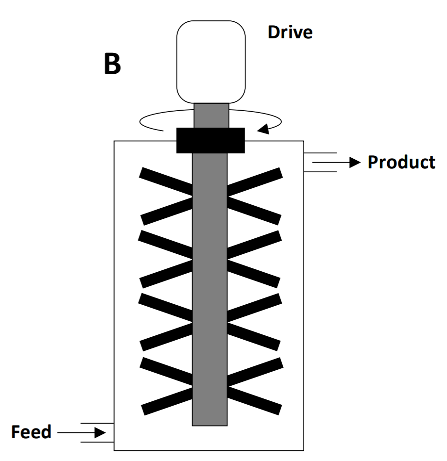
Table 2.2 summarizes some key features of several size reduction processes. There are some general features to note. Using traditional machines, to get from meter-sized rock to submillimeter size would require at least a primary crusher, a secondary crusher and a grinding mill. Quite possibly two secondary crushers might be needed (a secondary and then a tertiary crusher). SAG mills can often replace two or more of these. Still, the point is that multiple machines will typically be needed to get mined ore down to <1 mm. Capacity of size reduction machines decreases with output particle size. For instance several ball mills may be needed to handle the output of a single primary crusher. Size reduction requires a lot of energy. Specific energy consumption (energy per unit mass) increases dramatically with decreasing particle size. This is due in part to increasing surface area per unit mass as particle volume (mass) decreases.
| Table 2.2 - Characteristics of several types of size reduction machines. (The data may be somewhat out of date.) | |||||||
|---|---|---|---|---|---|---|---|
| Mill Type | Main Mechanism | Particle Size | Capacity (t/h) | Energy (kWh/t*) | Materials best suited to | ||
| Feed | Product | Well suited | Unsuited | ||||
| Jaw Crusher | Slow Compression | 0.15 - 3 m | 2.5-25 cm | 10-1000 | 0.2-0.7 | Hard, medium- hard | Soft, sticky |
| Gyrator | Slow Compression | 0.15-1.8 m | 2.5-25 cm | 35-3500 | 0.15-0.5 | Hard, medium- hard | Soft, sticky |
| Cone | Slow & Fast Compression | 2.5-25 cm | 5-40 mm | 10-600 | 0.4-2.2 | Hard, medium- hard | Soft, sticky |
| Rod Mill | Slow & Fast Compression, Abrasion | 5-25 mm | 70-800 m | 3-75 | 7-15 | Medium-hard | Sticky |
| Ball and Autogenous Mill | Fast Compression, Abrasion | 5-20 mm | 50-500 m | 2-12 | 10-30 | Medium-hard | |
| * a kWh is 1 kW for 1 hour or 1000 J/s x 3600 s = 3.6 x 10⁶ J; 1 t = 1 tonne (1000 kg). | |||||||
Media Attributions
- Ch2_F4_Size_Reduction_Mechanisms © Bé Wassink and Amir M. Dehkoda is licensed under a CC BY-NC (Attribution NonCommercial) license
- Ch2_F5_Jaw_Crusher adapted by Jeno Hwang
- Ch2_F6_Gyrator_Crusher © A. Gupta, D. Yan adapted by Jeno Hwang
- Ch2_F7_Output_vs_Throughput © J.C. Motz adapted by Jeno Hwang
- Ch2_F8_Grizzly_Screen © Bé Wassink and Amir M. Dehkoda is licensed under a CC BY-NC (Attribution NonCommercial) license
- Ch2_F9_Cone_Crusher © Bé Wassink and Amir M. Dehkoda adapted by Jeno Hwang is licensed under a CC BY-NC (Attribution NonCommercial) license
- Ch2_F10_Roll_Crusher © Bé Wassink and Amir M. Dehkoda is licensed under a CC BY-NC (Attribution NonCommercial) license
- Ch2_F11_Rod_Mill © Bé Wassink and Amir M. Dehkoda adapted by Jeno Hwang is licensed under a CC BY-NC (Attribution NonCommercial) license
- Ch2_F12_Rod_Mill © Bé Wassink and Amir M. Dehkoda is licensed under a CC BY-NC (Attribution NonCommercial) license
- Ch2_F13_Ball_Mill_Incomplete © Bé Wassink and Amir M. Dehkoda is licensed under a CC BY-NC (Attribution NonCommercial) license
- Ch2_F14_Ball_Mill © Bé Wassink and Amir M. Dehkoda) adapted by Jeno Hwang is licensed under a CC BY-NC (Attribution NonCommercial) license
- Ch2_F15_Autogenous_Mill © Peter Hayes is licensed under a All Rights Reserved license
- Ch2_F16_SAG_Mill is licensed under a CC BY-SA (Attribution ShareAlike) license
- Ch2_F17_Stirred_Mill © Bé Wassink and Amir M. Dehkoda is licensed under a CC BY-NC (Attribution NonCommercial) license
