Chapter VII: Electrowinning
7. Electrorefining
Most of the world’s copper is produced pyrometallurgically. This is generally not pure enough for most applications, despite being about 99.8% pure. The most viable method for purification of copper is electrorefining (ER). In this process, the impure copper is cast into anodes and placed into electrochemical cells. The impure copper is anodically dissolved by means of an electric current. The dissolved Cu+2 is plated onto high-purity copper cathode starter sheets. In the process the impurities present in the anode copper either stay with the anode or are precipitated as insoluble salts or are removed from the electrolyte by taking a bleed stream and purifying it. The process produces high purity copper (>99.99% Cu; <0.004% S + traces of other metals). Hence the great majority of the world’s primary copper production (i.e. neglecting scrap) involves either electrorefining or electrowinning. Electrochemistry figures very prominently in metal production. Nickel and cobalt also may be purified by electrorefining.
Staying with the example of copper electrorefining, copper metal is oxidized at the anode,
\[\ce{Cu -> Cu^2+ + 2e-}\qquad E^\circ = 0.34~\text{V}\tag{138}\]
and reduced at the cathode,
\[\ce{Cu^2+ + 2e- -> Cu}\qquad E^\circ = 0.34~\text{V}\tag{139}\]
The cathodes are negatively polarized and the anodes are positively polarized. Clearly ΔE° for this process is 0 V. The activity of copper in the anodes is only slightly less than one, and the copper concentration in the electrolyte is typically on the order of 1 m. Hence the thermodynamic cell voltage in practice is actually quite close to 0 V. However, there are other voltage drops that result in a cell voltage that is somewhat less than 0 V. (The cell voltage is Ecathode - Eanode < 0.) The following also contribute to the required cell voltage:
- Electrical resistance (0.01-0.02 V. Leads used to connect the electrodes to the power supply - called busbars.)
- Electrolyte resistance (0.11-0.13 V. Resistance to electrical conduction by means of ionic migration; lower than for EW electrolytes.)
- Cathodic overvoltage (0.04-0.08 V. This is due largely to organic coatings on the cathode copper surfaces. Organic additives are added to promote a smooth, continuous deposit. Alternatively periodic current reversal may also be employed to promote smooth deposit growth.)
- Anode and cathode connections (0.03-0.06 V. Electrical resistance of the connections.)
- Anode polarization (up to 0.01 V. Voltage required to corrode the anode copper.)
The total cell voltage is typically 0.25-0.3 V. The greatest contributor to the voltage is the electrical resistance of the electrolyte. Sulfuric acid concentrations are kept high to keep the resistance of the electrolyte low. Since the solution resistance of the electrolyte increases directly with the separation between anode and cathode, a narrow anode-cathode spacing is desirable. (ER tankhouses also involve very large numbers of cathodes and anodes, so minimizing the gap also is good for lowering capital costs of the associated infrastructure.) However, cathodes need to grow to a specified thickness (about 1.4-1.9 cm in electrorefining), starter sheets (the substrates onto which the metal is plated) and anodes may not be perfectly planar nor vertical and polycrystalline protrusions called dendrites can grow out from the cathodes towards the anodes, causing short circuits and loss of metal plating efficiency. For all these reasons the gap between cathodes and anodes in ER is roughly at least 2.5 cm. Note that in ER as the cathode grows, the anode gets thinner. The conductivity of typical ER electrolytes is 0.5-0.7 Ω-1 cm-1. Typical current densities are 190-260 A/m2 and cathodes typically are 1 m x 1 m. Given a cathode-anode spacing of 2.7 cm, a current of 250 A and a conductivity of 0.7 Ω-1 cm-1, the resistance of the electrolyte would be,
\[R=\left(\frac{1}{0.7~\Omega^{-1}\,\text{cm}^{-1}}\right)\times 2.7~\text{cm}\times\left(\frac{1}{10^{4}~\text{cm}^2}\right)=0.000386~\Omega\tag{140}\]
From V = IR the voltage drop would be,
\[V=250~\text{A}\times0.000386~\Omega=0.097~\text{V}\tag{141}\]
which is close to the lower end of the typical range of voltage drops due to solution resistance listed previously.
Impurities
The table below lists the common impurities in anodes and the purer cathodes. The main impurities are As, Bi, Ni, Pb, Sb, Se and Te. If an element has an E° that is less than E°Cu+2/Cu (0.34 V), then it can dissolve from the anode. (A lower standard reduction potential means that the element is more easily oxidized.) For an impurity metal in the anode,
\[\ce{M_{anode} -> M^{n+}_{(aq)} + n e-}\tag{142}\]
The reduction potential (for the reduction half reaction) is given by,
\[E=E^\circ-\frac{2.303RT}{nF}\log\!\left(\frac{a_{\mathrm{M,\,anode}}}{a_{\mathrm{M^{n+}}}}\right)\tag{143}\]
The activity of metal impurity in the anode will be low. If the activity of the ion in solution is also low, the reduction potential will be close to E°.
| Table 7.1 - Impurities in copper before and after ER. | ||
|---|---|---|
| Impurities | Anodes, % | Cathodes, % |
| As | 0-0.3 | <0.0002 |
| Bi | 0-0.001 | <0.0001 |
| Fe | 0.002-0.03 | <0.002 |
| Ni | 0-0.5 | <0.001 |
| Pb | 0-0.1 | <0.0005 |
| Sb | 0-0.3 | <0.0002 |
| S | 0.001-0.003 | <0.001 |
| Se | 0-0.02 | <0.0002 |
| Te | 0-0.001 | <0.0001 |
| Ag | trace-0.1 | <0.001 |
| Au | 0-0.005 | <0.00001 |
| PGM* | trace | |
*PGM = platinum group metals (Rh, Ir, Ru, Os, Pd, Pt)
Iron, for example, has E°Fe+2/Fe = -0.41 V. It is much easier to oxidize than copper. Now, however, since the reduction potential for Fe+2 to Fe is substantially lower than that for Cu+2 to Cu, copper will preferentially plate over iron. (Fe+2 having a lower E° than Cu+2 means that Cu+2 is a stronger oxidant; Fe+2 is harder to reduce.) On the other hand, elements with an E° greater than that of Cu+2 will not dissolve from the anode. Thus electrorefining is very selective. Only species with reduction potentials similar to that of E°Cu+2/Cu will dissolve from the anode (at least by anodic oxidation) and plate at the cathode. Even then, kinetic factors also would come into play. If a species has a substantial cathodic overpotential for reduction, its tendency to reduce and co-plate with copper at the cathode would be diminished.
A partial table of standard reduction potentials is reproduced below. The first column indicates the principal species that would form in solution. Inspection of the data indicates that mainly Fe, Ni, Pb, Sb, As and Bi should dissolve.
The other way that impurities can enter the cathodes is by occlusion (or entrainment). Cathode surfaces are polycrystalline and not perfectly smooth. Microscopic cavities form, which contain the electrolyte. These may grow over with
| Table 7.2 - Some standard reduction potentials relevant to Cu ER. | |
|---|---|
| Half reaction | E° V |
| Au+3 + 3e- = Au | 1.42 |
| Ag+ + e- = Ag | 0.80 |
| Cu+2 + 2e- = Cu | 0.34 |
| BiO+ + 2H+ + 3e- = Bi + H2O | 0.32 |
| *HAsO2 + 3H+ + 3e- = As + 2H2O | 0.25 |
| SbO+ + 2H+ + 3e- = Sb + H2O | 0.21 |
| 2H+ + 2e- = H2 (for reference) | 0 |
| Pb+2 + 2e- = Pb | -0.13 |
| Ni+2 + 2e- = Ni | -0.23 |
| Fe+2 + 2e- = Fe | -0.41 |
* Or perhaps H2AsO3.
copper metal and trap small amounts of electrolyte within the cathodes. Impurities in the electrolyte, including copper sulfate and sulfuric acid are then occluded. This is the principal origin of impurities in the cathodes. Notes on specific impurities follow.
(a) Gold and platinum group metals do not dissolve from the anode. Their reduction potentials are too high. These metals stay in the residues of the anodes. Anodes are not completely dissolved. They are removed and replaced after about 85% reaction. Precious metals may be a significant source of revenue.
(b) Silver does partially dissolve,
\[\ce{Ag_{anode} -> Ag+ + e-}\tag{144}\]
but a low concentration of sodium chloride (~0.05 M NaCl) in the electrolyte precipitates most of this as insoluble AgCl:
\[\ce{Ag+ + Cl- -> AgCl(s)}\qquad \frac{1}{K_{\mathrm{sp}}} = 5.6 \times 10^{9}\tag{145}\]
The net reduction reaction is,
\[\ce{Ag_{anode} + Cl- -> AgCl + e-}\tag{146}\]
In fact, E° for Ag+/Ag is 0.80 V. This is considerably higher than that for Cu+2/Cu (0.34 V). This should preclude silver dissolving in the first place. But,
\[\ce{AgCl + e- -> Ag + Cl-}\qquad E^\circ = 0.22~\text{V}\tag{147}\]
Since this is less than E°Cu+2/Cu, and chloride is present in the electrolyte, conversion of anode silver to solid AgCl is favourable. Most of the AgCl reports with the anode residues. Whatever does end up in the cathode results from occlusion of suspended particles in the electrolyte. Silver may be present as a copper-silver solid solution and as compounds with sulfur, selenium and tellurium, depending on relative concentrations. These compounds are too stable to corrode. It is evident then that mechanisms of dissolution may be complex.
(c) Sulfur, selenium and tellurium form stable copper compounds with many metals (e.g. Ag2Se, Cu2Se, Ag2Te4, Cu2S etc.), which are not electrochemically oxidized. These elements mainly report with the anode residues.
(d) Lead and tin (tin was not mentioned in the tables above) are readily corroded, but form quite insoluble precipitates of PbSO4 and a basic tin(II) sulfate. As a result these elements do not dissolve to any significant degree in the electrolyte. Some cathode contamination by occlusion occurs.
(e) Arsenic, bismuth, cobalt, iron and nickel are all less noble than copper (i.e. they are more easily oxidized) and can enter the electrolyte as solution species (e.g. HAsO2, BiO+, Co+2, Fe+2 and Ni+2, respectively; see table of reduction potentials). Much of the antimony (~60%) and some of the arsenic (~25%) end up staying in the anode residues, possibly as a result of forming stable compounds with copper (e.g. arsenides) during anode casting. In principle the impurities could plate at the cathode, but many have E° < E°H+/H2 (e.g. E°Co+2/Co = -0.28 V). The potential at the cathode is around E°Cu+2/Cu = 0.34 V, i.e. the potential for copper reduction is too oxidizing to allow less noble ions to reduce. (Besides, even if they could plate, the strong acid of the electrolyte would redissolve them in some instances.) This illustrates the beauty of electrorefining. The impurity metals that are more easily corroded than copper (E° < 0.34 V) can’t electrochemically plate at the cathode, while those that have E° > 0.34 V can’t be corroded from the anodes. The purification method is thermodynamically tuned to be very selective for copper.
The case of bismuth is different. The E° for BiO+/Bi is 0.32 V, which is quite similar to E° for Cu+2/Cu. The differences in the two potentials are quite small and this might allow some Bi to be electrochemically deposited, in principle.
Nevertheless, all the corroded species build up in the electrolyte over time and eventually would contaminate the cathodes by occlusion. This is the main mechanism by which impurities enter the cathodes. Because of this they have to be removed from the electrolyte. A bleed stream is taken from the electrolyte and subjected to purification to remove the impurities from the circuit. Since the impurities concentrations in the anodes are low, the bleed rates are also low (0.1-0.5 m3 of electrolyte per tonne of copper metal plated.)
Electrolyte purification
There are a number of methods available for purifying the bled electrolyte. One method is to first plate copper electrochemically from the electrolyte. This is done in three stages. These are called “liberator” cells. The first stage produces quite high purity copper cathodes. This is essentially an electrowinning operation. In the second stage an impure copper product is formed that can be recycled to the furnace for generation of copper anodes. In the third stage most of the arsenic, antimony and bismuth are removed as well. The copper product is highly contaminated with these elements. The cathodes may be used for production of arsenic or recycled to the smelter. (In the smelter these elements are partially rejected as slags and dusts. This avoids build-up of these impurities in the process.) The third stage in particular is quite energy inefficient due to the low concentrations of ions in solution. In order to maintain high plating rates, high voltages are required. This results in strongly reducing conditions at the cathode and some arsine gas (AsH3) is also evolved. Arsine is extremely toxic and must be collected. In arsenic-containing EW electrolytes there is also a danger of arsine generation.
After the third stage the solution contains mainly sulfuric acid, nickel, cobalt and iron sulfates. Water is evaporated and the sulfate salts of the metals precipitate. The precipitation is driven in part by the resulting high H2SO4 concentration (source of high sulfate concentration). What is left is a high concentration H2SO4 solution (1000 g/L or ~10 M). This is mostly recycled to electrorefining to make up for lost acid.
An alternative to the first EW stage is to remove copper as CuSO4·5H2O. This is done by adding copper metal (“shot”) and reacting it with oxygen:
\[\ce{Cu + 1/2 O2 + H2SO4 -> CuSO4 + H2O}\tag{148}\]
Evaporation and cooling of the solution precipitates much of the solution copper as CuSO4·5H2O. The product contains a little iron and nickel as well. It may be sold.
Plating conditions
Organic additives are introduced to the electrolyte for a number of reasons. One typical additive is “bone glue,” a mixture of natural proteins. It is added at 1-10 mg/L. It is added to minimize the growth of protrusions on the cathode surface. Glue acts by adsorbing particularly on the tips of protrusions. This results in an insulating layer that inhibits further deposition of metal. The adsorption of glue to varying degrees on the cathode surfaces results in a slightly higher overall resistance and a consequent voltage drop, as was noted previously. The same effect can be attained by a technique called periodic current reversal (PCR). For a brief interval, repeated regularly, the cell polarity is switched so that plating occurs briefly on the anodes and corrosion of copper from the cathodes. The protrusions are the most rapidly dissolved, while the indentations are the slowest to dissolve. The result is that protrusions are prevented from growing. A side benefit is that higher current densities can also be employed, resulting in greater overall plating rates. Other additives are also added for various reasons. For instance, flocculants may be added to promote flocculation and settling of fine precipitates and solids derived from the anodes. This helps prevent impurity occlusion in the cathodes.
The electrolyte is heated by steam coils to 60-65°C entering the circuit and leaves at 55-60°C. Some heating of the electrolyte occurs as a result of the solution resistance. The electrolyte is circulated at a slow rate (~0.02 m3/min). This ensures that Cu+2 in solution is transported from anode to cathode. It also carries away impurities and aids in distribution of additives to the solution.
A cathode substrate is needed for plating copper. These tend to be thin sheets of copper metal (0.5-1 mm). They are plated onto titanium blanks. They are plated for about 24 hours, after which they are mechanically removed from the titanium substrates. Due to an adherent, conductive film on titanium, the copper sheets are easily separated from the substrate. Titanium is expensive, but the process is easier than previously practiced alternatives. Electrorefining cathodes are plated for about 10-14 days, whereas the starter sheets are plated for one day, so the number of titanium sheets needed is a small fraction of the total number of cathodes being plated.
In principle, the higher the current density, the faster the copper cathode production rate. However, much above 250 A/m2 (or 300 A/m2 with PCR) anode passivation occurs. The resistance of the anode greatly increases and copper corrosions ceases. This has been attributed to rapid buildup of CuSO4 in the electrolyte at the anode surface and resultant precipitation of CuSO4·xH2O. This would occur if the solubility of copper sulfate was exceeded. The precipitate is non-conductive and forms an insulating coating on the anodes. Passivation is prevented by keeping the copper concentration in the electrolyte well below saturation (typically around 40-45 g Cu+2/L), operating the cells at higher temperature (~60°C, which increases the solubility of copper sulfate), maintaining good circulation and keeping the current density low enough. In addition, very high current densities result in rough cathodes with more occlusion of electrolyte.
Efficiency and energy consumption
Current efficiency for ER is on the order of 90-96%. The main sources of loss are stray currents to ground (1-3%), anode-cathode short circuits (1-3%) and reoxidation of copper cathode (1%). Stray currents arise from fortuitous conduction pathways, such as spilled electrolyte. Copper dendrites growing from cathode to anode cause short circuits. These may be detected by infrared scanners. The nodules are broken off to resume plating. The cathode is only weakly negatively polarized (the thermodynamic cell voltage is almost zero). Hence oxygen in solution can attack the copper in acidic solution and oxidize it. This occurs to a small extent.
\[\ce{Cu + 1/2 O2 + H2SO4 -> CuSO4 + H2O}\tag{149}\]
Oxygen is not generated at the anode; copper metal corrosion is much more favourable than water oxidation. However, oxygen is slightly soluble in the aqueous solution and enters from the air. Oxygen may also oxidize ferrous to ferric to a small extent, and ferric can corrode copper:
\[\ce{2Fe^{3+}_{(aq)} + Cu -> 2Fe^{2+} + Cu^{2+}}\tag{150}\]
Quantities such as energy requirement and copper production rate may be calculated from the Faraday’s Law relationships. The energy requirement for copper ER with 96% current efficiency and 0.25 V applied potential is 220 kWh/t Cu. In EW the energy requirement is 1900-2000 kWh/t Cu. The difference is due mainly to the low cell voltage in ER compared to the higher voltage in EW (~2 V). Hence ER for copper is not all that energetically demanding. In addition to the ER process itself, the purification process for the bleed stream requires some energy (roughly 25 kWh/t Cu produced). This is about 1/10 the energy for copper cathode production (including the starter sheets).
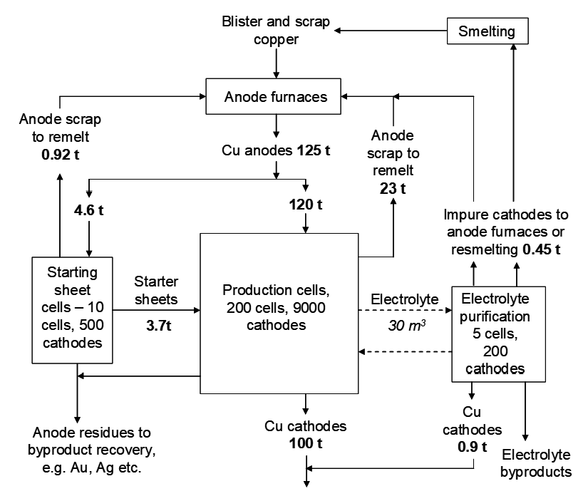
Flowsheet
Once the anodes have been about 85% consumed they are removed from the cells, washed to displace the residues (“slimes”) and recycled back to anode casting. The residues may be collected and processed for precious metals recovery, which can be a substantial source of revenue. A flowsheet is presented in Figure 7.1 that schematically depicts an ER process with the bleed stream being purified by electrowinning as described previously. Blister copper is the term for primary copper from pyrometallurgical processing. Approximate mass and volumetric flows are included. Note the substantial recycle of copper anode material and that a small amount of high-purity copper metal is produced from the bleed stream purification process. The number of starter sheet cells is relatively small. Starter sheets are quite thin.
Other operational aspects
Anodes and cathodes are set in cells in a parallel arrangement with each anode between two cathodes. The electrolysis is carried out in a parallel circuit, not in series. This keeps all anodes at the same potential and all cathodes at the same, slightly lower potential. Each cell contains 30-50 anodes, depending on the plant. Cells are operated in series and can be isolated for purposes of installing or recovering cathodes, spent anodes and residues, etc. Electrical contact is made through a system of copper metal contacts. Cells are made of concrete with polymer liners or aggregate in plastic. The electrical contacts are profiled to keep the cathodes and anodes at the right spacing. Care is taken to ensure that cathode starter sheets and anodes are planar and aligned properly in the cells. This ensures good uniform corrosion of anodes and plating of cathodes, as well as avoiding direct short circuits between cathodes and anodes.
Some statistics for typical copper electrorefining operations are provide in Table 7.3 that follows below. The process takes on the order of 10-14 days per set of cathodes, which is about twice as long as electrowinning of copper. At the start of the process a set of anodes and a set of cathode starter sheets are placed into the cells. For n anodes there are n+1 cathodes (opposite of electrowinning). After
10-14 days the cathodes are removed, then a new set of cathode starter sheets are installed and the process continues. Each set of cathodes is removed and washed. Cathodes are melted and cast into now very pure form. After two sets of cathodes are recovered from one set of anodes the electrolyte is drained away. Spent anodes are washed to remove residues and the cells are washed out to recover the residues. These may be treated for precious metals recovery. The spent anodes are then recycled to anode casting, which is done by melting the copper metal.
The circulation rate is high enough to ensure good migration of copper. However, circulation rates need to be low enough to allow dislodging particles of anode residues to fall to the bottom of the cell, and not be occluded in the cathodes. Energy consumption refers to DC voltage requirements. If power is converted from AC to DC there is a small loss here as well.
| Table 7.3 - Some typical copper electrorefining plant statistics | |
|---|---|
| Copper production (t/d) | 400-1100* |
| Number of cells | 800-2400 |
| Cell inner dimensions L x W x D (m) | 4-5 x 1.1 x 1.2 |
| Anodes: %Cu | 99.5-99.7 |
| L x W x thickness (m) | ~1 x ~1 x ~0.05 |
| Weight (kg) | 310-380 |
| Center-line spacing (cm) | 10 |
| Lifetime (days) | 20-28 |
| Anode consumption (%) | 80-87 |
| Cathodes: Lifetime (days) | 10-14 |
| Starter sheet weight (kg) | 5-6 |
| Weight (kg) | 130-165 |
| Total metallic impurities (%) | 0.001-0.003 |
| Electrolyte composition (kg/m3): | |
| Cu | 43-50 |
| H2SO4 | 180-200 |
| Ni | 2-10 |
| As | <0.01-10 |
| Fe | 0.2-1 |
| Sb | 0.15-0.35 |
| Bi | 0.04-0.15 |
| Cl | 0.03-0.04 |
| Temperature (°C) | 60-65 |
| Circulation rate (m3/min per cell) | 0.015-0.02 |
| Power: Cathode current density (A/m2) | 190-280 |
| Current efficiency (%) | 90-96 |
| Cell voltage (V) | 0.25-0.3 |
| Energy consumption (kWh/t Cu) | 220-270 |
Media Attributions
- Ch7_F23_Cu_Electrorefining_Process © Bé Wassink and Amir M. Dehkoda is licensed under a CC BY-NC (Attribution NonCommercial) license
