Chapter IV: Introduction to Leaching
7. Agitation
Principles
An agitator or mixer is a device that imparts energy to a fluid by means of a rotated impeller. The hydraulic behaviour of an impeller is much like that of a pump, with the difference that an impeller does not have a housing.
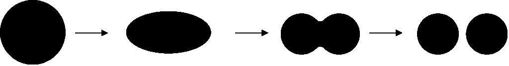
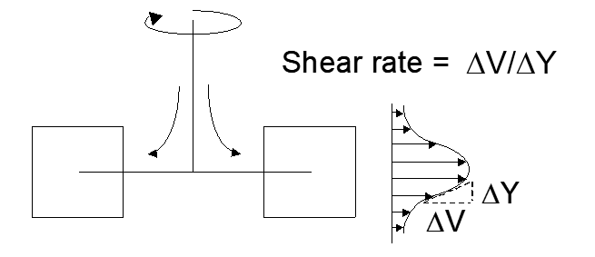
The fluid may be any mixture of liquids, solids or gas. The mixer provides two functions: flow and shear, in varying degrees. Flow is essentially pumping of fluid or slurry. Shear can be thought of as a tearing of the fluid or slurry. It generates turbulence. Shear occurs when a fluid passes through a significant velocity gradient. The fluid or
slurry then undergoes rapid change in velocity. This results in differential forces. This is important for dispersing one phase in another, for instance. Shear greatly increases the surface area of the dispersed phase. This is illustrated schematically below:
Different impellers impart different degrees of both effects. A table of applications and impeller types is provided below. The different impeller types are discussed further on. Heat transfer and blending involve quite simple mixing. Solids suspension is important for effecting good mass transfer of reagents to solids for leaching, for instance. Solids suspension is probably the single most important agitation function in hydrometallurgy. Gas-liquid dispersion is needed for getting low-solubility gases into solution, again for example for leaching involving oxygen. Liquid-liquid dispersion is required when a chemical species must be transferred from one immiscible phase to another (e.g. in solvent extraction). Emulsification is not common in hydrometallurgy. De-agglomeration is the breaking up of particle aggregates into its constituent smaller particles by means of high shear.
| Table 7.1 - Some Common Mixing Operations and the Type of Impellers Required | ||
|---|---|---|
| Application | Impeller Type | |
| FLOW | Heat transfer | Hydrofoils |
| Blending | Propellers | |
| Solids suspension | Axial flow impellers | |
| SHEAR | Gas-liquid dispersion | Radial flow impellers |
| Liquid-liquid dispersion | Flat blade turbines | |
| Emulsification | Disc turbines | |
| De-agglomeration | Homogenizers | |
The effectiveness of an impeller is limited by the viscosity of the fluid or slurry. A maximum of ~500,000 cps (centipoises) is the limit for using an impeller. (Water at 20°C has a viscosity of about 1 cps.) Agitators are comprised of:
- A power source (usually an electric motor).
- A transmission (e.g. a gearbox) to convert applied power into torque.
- A shaft to transmit power from the motor to the impeller.
- An impeller transmits energy to the fluid.
- A seal system if the tank is closed and under pressure.
The power required to drive an impeller is given by the equation:
\[\ce{P = N_p \rho N^3 D^5\ (Watts)} \tag{22}\]
where Np = a constant
Ρ = fluid density (kg/m3)
N = rotation rate (sec-1)
D = impeller diameter (m)
(The actual power required is greater than that indicated by the equation due to transfer inefficiencies.) When one considers the units, this is reasonable:
\[\text{kg m}^{-3} \times \text{s}^{-3} \times \text{m}^5= \text{kg m sec}^{-2} \times \text{m s}^{-1}= \text{N m sec}^{-1}= \text{J sec}^{-1}= \text{W (Watts)}\]
The hydrodynamics of various impeller designs may be compared by means of a dimensionless “power number,” Np,
\[\ce{N_p = \frac{P}{N^3 D^5 \rho}} \tag{23}\]
This is the ratio of applied power to the actual effect. It varies from one impeller to the next, i.e. it's a characteristic of the impeller. It is a friction factor or drag coefficient. The larger NP is, the harder it is to turn the impeller; a measure of friction loss. Naturally the power number for an impeller depends on its shape, but, it also depends on the Reynolds number. (Recall that the Reynold's number, Re, relates inertial force and viscous force; it is the ratio thereof. Hence, as we would expect, the viscosity of the fluid plays an important role in the power number.) For fully turbulent flow the power number for a given fluid is roughly constant. And, turbulent flow is what is needed for good mixing in hydrometallurgical applications.
Low shear/high flow impellers have lower NP than high shear impellers. An efficient hydrofoil may draw 1/20 of the power of a radial turbine (see below for impeller types). However, the power number may also affected by viscosity and clearance between the tank bottom and the impeller. Under fully turbulent conditions (which is desirable for good mixing) the power number does not change with flow velocity. Clearance from the bottom of the tank to the impeller is an important variable. For efficient hydrofoils the clearance is normally equal to one impeller diameter. Decreasing clearance impedes fluid flow and increases the power number. This is a complex subject and will not be treated in detail here. Engineering of mixing systems is an important task in hydrometallurgical processes.
Pumping capacity and shear can be compared for a given impeller and related to the impeller diameter and its rotation speed. The relationships can be obtained from dimensional analysis.
(i) As above,
\[ P \propto \rho N^3 D^5 \tag{24} \]
Q = pumping capacity in units of [latex]m^3 sec^-1[/latex] (volume flow rate). Therefore,
\[Q \propto N D^3 \tag{25}\]
(Volume pumped is directly related to the impeller diameter3. In fact,
\[Q = N_q N D^3 \tag{26}\]
where Nq is the constant of proportionality, and is called the flow number. As with the power number, it is different for different impeller designs.) Let H = shear, also called velocity head. It has units of energy/mass, which is reasonable for imparting turbulence to a fluid:
\[\text{J kg}^{-1} = \text{N m kg}^{-1} = \frac{\text{kg m}^2 \text{s}^{-2}}{\text{kg}} = \text{m}^2 \text{s}^{-2} \;\text{(i.e., velocity}^2\text{27}\]
Hence,
\[ H \propto N_2 D_2 \tag{28}\]
Then,
\[P \propto \rho N^2 D^2 \cdot N D^3 \tag{29}\]
\[P \propto \rho H Q \tag{30}\]
(ii) From:
\[P = N_P \rho N^3 D^5 \tag{31}\]
we obtain,
\[\ce{N = \left( \frac{P}{N_p \rho} \right)^{1/3} D^{-5/3}}\]
For a given fluid, fixed power and a given impeller,\[ \frac{P}{N P \rho} \]is a constant. It follows that,
\[N \propto D^{-5/3} \quad \text{and} \quad D \propto (1/N)^{3/5} \tag{32}\]From:
\[P \propto \rho H Q \tag{33}\]
and for a given fluid (fixed ρ), and recalling that,
\[\ce{H \propto \frac{P}{Q} \propto \frac{N^3 D^5}{N D^3} \propto N^2 D^2} \tag{34}\]
Recalling that \[ N \propto D_{-5/3} \] then,
\[ H \propto (D_{-5/3})^2 D_2 \propto D_{-4/3}\tag{35} \]
(iii)\[ Q \propto N D_3 \propto D_{-5/3} D_3 \propto D_{4/3} \tag{36}\]
(iv) Finally, the ratio Q/H may be calculated:
\[\ce{\frac{Q}{H} = \frac{D^{4/3}}{D^{-4/3}} = D^{8/3} = \frac{(1/N)^{3/5\,4/3}}{(1/N)^{3/5\,-4/3}} = (1/N)^{8/3\,5} = (1/N)^{8/5}} \tag{37}\]
Therefore, at constant power,
\[ \frac{Q}{H} \propto D_{8/3} \propto \frac{1}{N_{8/5}}\tag{38} \]
What this means is that for a given fluid, power input and impeller, the ratio of flow to shear for a particular impeller varies as impeller diameter 8/3. In other words, flow increases by almost the cube of diameter. For a given power, increasing the impeller diameter dramatically increases the flow effect relative to the shear effect.
Similarly, increasing the rotation speed (N) at constant power increases shear relative to pumping capacity, though to a somewhat smaller extent (the exponent is 1.6). For high shear, small impellers run at high speed are most suitable. For high flow, large impellers at low speeds are best. Intuitively this should stand to reason. A low speed at the impeller tip should impart low shear. Obviously high shear and high pumping capacity are conflicting objectives. Where both are needed a balance of the effects must be struck.
The various parameters of concern for an impeller are N, D, P, Q, H, NP and Nq. The two dimensionless numbers are characteristics of the impeller. The density () is a characteristic of the fluid. In the preceding discussion, we compared the effects of N and D on flow and shear with other parameters held constant. There are also many bases of comparison for different impellers, which are important considerations for design. For instance, power required for a given flow and speed, or power required for constant speed and diameter, or power required for constant flow and diameter, etc. To illustrate, for a given fluid (constant ), impeller size (constant D) and flow (Q = ND3 = constant, i.e. the desired flow effect is fixed or known) the power required for two different impellers can be compared, As above,
\[ P = N_{pp} N_3 D_5\tag{39} \]
Then for impellers 1 and 2 the power required for the two can be compared as follows:
\[\ce{\frac{P_2}{P_1}
= \frac{N_{p2}\rho\,(Q/N_{q2})^3 D^{-4}}{N_{p1}\rho\,(Q/N_{q1})^3 D^{-4}}
= \frac{N_{p2}}{N_{p1}} \left(\frac{N_{q1}}{N_{q2}}\right)^3} \tag{40}\]
Impellers and Tanks
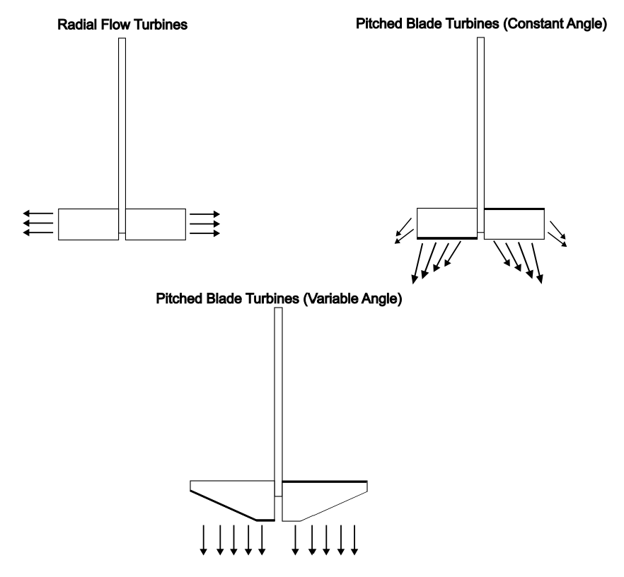
High shear occurs mainly in the vicinity of the impeller tip as indicated in the diagram below (Figure 7.2). Hence it is important that all the fluid be directed to the impeller blades. With blades attached to a central disk fluid is directed towards the blades and is prevented from flowing axially past them.
There are three general classes of impellers. These are illustrated in Figure 7.3.
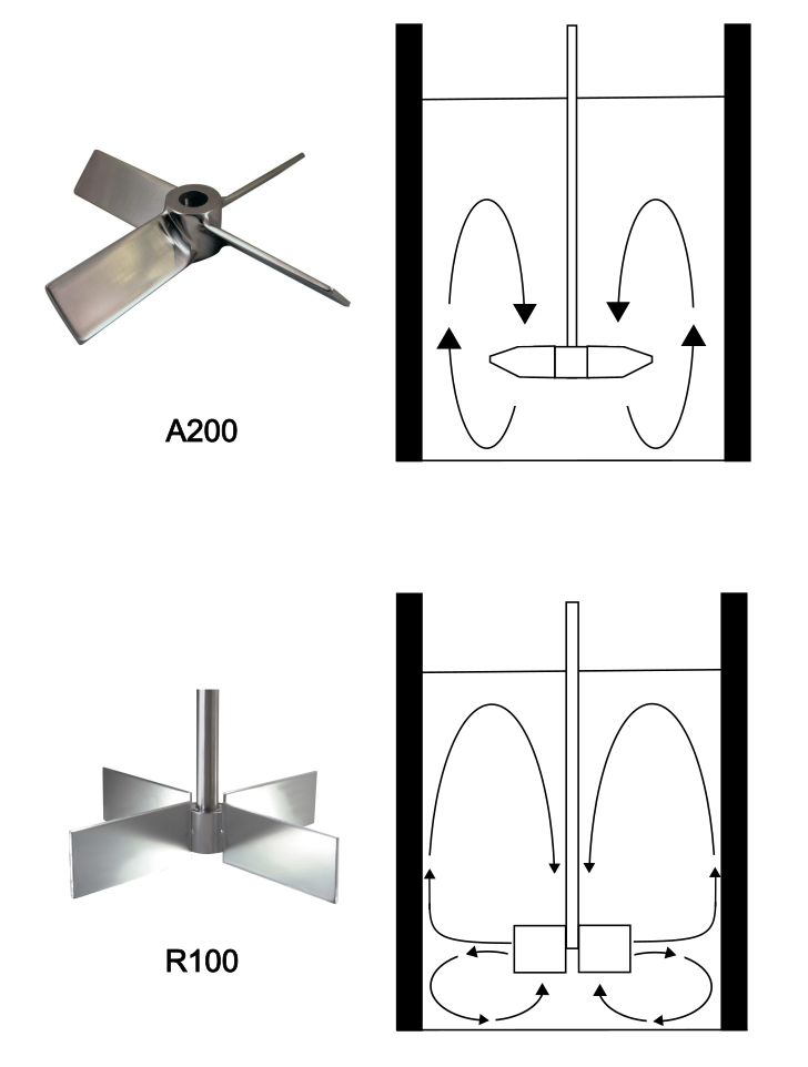
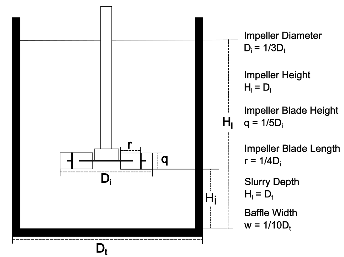
Aspects of the tank are also important in design. An agitator operating in a cylindrical tank with smooth sides will simply swirl the fluid around the tank with little up and down circulation. In addition, a vortex is created in the middle with the effect that the fluid is pushed up the sides of the tank. This simply converts kinetic energy into gravitational potential energy and lowers mixing efficiency. To overcome this, baffles are placed on the sides of the tank to induce a vertical circulation, as shown in Figure 7.4. Normally four, equidistant baffles are used. For a cylindrical flat bottom tank, which is common in hydrometallurgy, the ratio of the tank diameter to the fluid depth is normally about 1.0. (An agitated autoclave chamber is not an upright cylinder.) An illustration of a stirred tank reactor using a radial turbine impeller is shown in Figure 7.5. This application is required when mixing gases (e.g. oxygen or air) into a leach slurry.
Where there is to be an overflow of slurry the solids must be very well suspended, which may require a larger agitator. Where tanks are arranged in series and slurry overflows from one tank to the next, some of the solids will migrate across the top of the slurry and flow into the next tank, unless measures are taken to prevent this. This greatly reduces residence time in the tank and therefore the extent of leaching. The term for it is, "short circuiting." It can be overcome by using downcomers. These are pipes that dip deep into the tank to deliver slurry from the previous tank. Upcomers are used to draw off slurry from near the bottom of the tank, rather than allowing it to simply overflow from the top. This acts to prevent coarse, heavy solids from collecting at the bottom of the tank. Flow in the vicinity of the upcomer is fast and draws up the large particles.
Agitation rate, Solids Suspension and Leaching Rate
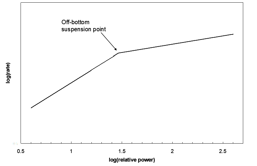
Leaching involves a heterogeneous reaction between a solid and a solution. (In leaching oxygen may also be used, but usually it reacts slowly with the solids, and an intermediate oxidant (like Fe+3) is used as well; ferric oxidizes the minerals of interest and oxygen oxidizes Fe+2 back to Fe+3. Since the leaching reaction is heterogeneous the key is to get solution to the solids rapidly. For this to occur efficiently the solids should be suspended. (If the solids lie in a heap at the bottom of the tank, obviously it will take a lot longer for solution to make its way to the particles.) Studies of agitated leaching often include an investigation of impeller speed (rotation rate) and reaction rate. Reaction rate can be expressed in numerous ways, but it is essentially the rate of consumption of a reactant, or the rate of production of a product, i.e. change in concentration per unit time, or just change in amount per unit time. The typical kind of plot obtained in such studies is shown in Figure 7.6. At some threshold power level a small fraction of the solids starts to become suspended.
The extent of particle suspension increases as power increases. Then the log of the reaction rate rises linearly with log(power), or with log(rotation rate) (as is often presented instead). This continues until all the solids have been suspended. This is called the off-bottom suspension point. Beyond this point, further increases in applied power result in only modest gains in reaction rate. What is occurring here is that the solids begin to become more uniformly distributed throughout the slurry, and the increased turbulence does slightly improve mass transport and hence reaction rate.
There are other considerations as well. For example, in bioleaching involving stirred tanks air is added as the oxidant. Good dispersion of the gas requires an impeller that can impart shear. But, this means that the bacteria doing the leaching also experience high forces that can physically destroy them. Hence a trade-off has to be worked out. In gold leaching activated carbon is often added to the leaching slurry. It is a very good adsorbent for [Au(CN)2]-. The larger carbon particles are then recovered by screening to separate them from the ore solids, and the solution. If the impeller tip speed is too fast, then the carbon particles get rapidly broken up, making separation by screening impossible.
Media Attributions
- Ch4_F19_Shear_Increased_Surface_Area © Bé Wassink and Amir M. Dehkoda is licensed under a CC BY-NC (Attribution NonCommercial) license
- Ch4_F20_Turbine_Effected_Shear © Bé Wassink and Amir M. Dehkoda is licensed under a CC BY-NC (Attribution NonCommercial) license
- Ch4_F21_Impeller_Styles © Bé Wassink and Amir M. Dehkoda adapted by Jeno Hwang is licensed under a CC BY-NC (Attribution NonCommercial) license
- Ch4_F22_Impeller_Flow © Bé Wassink and Amir M. Dehkoda adapted by Jeno Hwang is licensed under a CC BY-NC (Attribution NonCommercial) license
- Ch4_F23_6_Blade_Turbine © Bé Wassink and Amir M. Dehkoda adapted by Jeno Hwang is licensed under a CC BY-NC (Attribution NonCommercial) license
- Ch4_F24_Applied_Power_V_Leaching © Bé Wassink and Amir M. Dehkoda is licensed under a CC BY-NC (Attribution NonCommercial) license
