Chapter VII: Electrowinning
5. Copper Electrowinning Practice
Specifications
LME (London Metals Exchange) grade A copper has the following specifications:
- Pb < 5 ppm
- S < 15 ppm
- Other impurities <49 ppm
- Cu >99.993%
A major source of sulfur impurity is sulfate from occluded electrolyte.
Cells and hardware
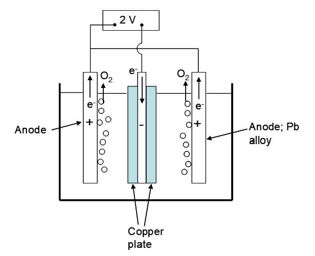
A diagram depicting a simplified cell is shown below in Figure 5.1. Cathodes and anodes are connected in a parallel arrangement. Cathodes are interleaved between pairs of anodes. A cell will have n cathodes and n +1 anodes. Then metal may be plated onto both sides of every cathode, making the most of the available plating surface area. A typical Cu EW cell will have up to 60 cathodes and 61 anodes. Cathode copper is often plated onto stainless steel blanks or starter sheets, usually ~3 mm thick and 1 m X 1-1.2 m surface dimensions (Jenkins et al. 1999, p. 493-567). Stainless steel is used to minimize corrosion. Sometimes copper starter sheets are used instead. These are plated separately and are 0.5-1 mm thick. The starter sheets are removed from a cathode substrate (such as titanium, to which copper adheres very weakly) and placed into the main EW cells. A schematic illustration of a cell is shown in Figure 5.2 below.
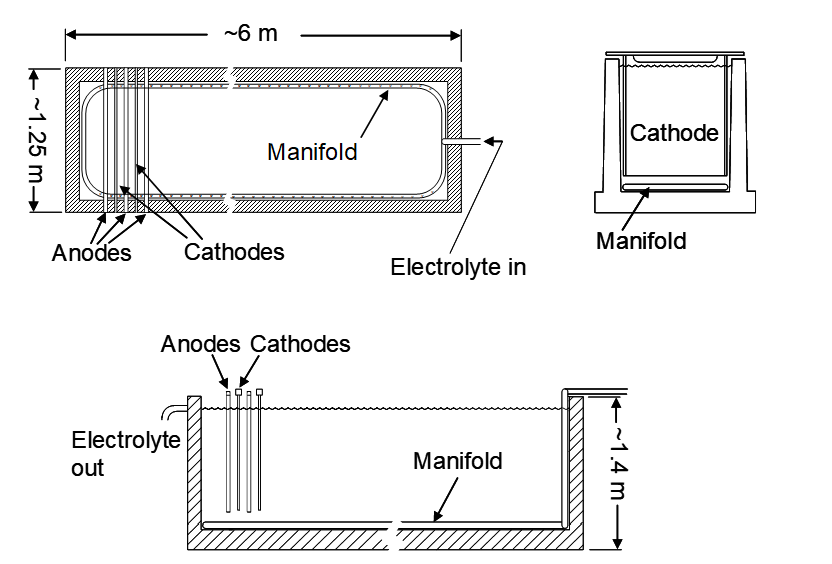
Cell dimensions are on the order of 6 m long x 1.4 m deep by 1.25 m wide (Davenport et al. 2002), with some variation. Long conductive bars called busbars conduct electricity to the electrodes. Previously the electrolytic cells were made of concrete and had to be lined to prevent corrosion. PVC was a common liner. Modern cells tend to be made of polymer concrete (aggregate in a plastic binder). Cells are electrically insulated from ground to minimize stray currents that lower current efficiency. Regular cleaning is required to remove lead sludge due to slow anode corrosion (mainly as PbO2). Excessive build-up can eventually compromise cathode quality (Pfalzgraff p. 217-221). A typical tankhouse will have hundreds of cells.
The cathode-anode gap needs to be as small as possible to minimize the IR loss due to solution resistance. Cathodes are grown to a thickness of about 0.5 cm and due to misshapen electrodes and cathode protrusions there is a limit on how small the gap can be. The cathode-cathode centre-line spacing is commonly 9.5-11.4 cm (Prasad et al. 1992, p.95-118). With 0.3 cm thick steel cathode sheets and 0.6 cm thick anodes, and cathodes that grow to 0.5 cm thickness, the anode-cathode gap is about 4.3-5.3 cm at the start of cathode growth and 3.8-4.8 cm at the end. Steel starter sheets, being more rigid than thin copper starter sheets, have allowed for the narrowing of the cathode-anode gap, which lowers resistance losses.
Anodes are typically made of a lead alloy as mentioned earlier, although the DSA's are starting to appear. Typically anodes are ~0.6 cm thick (Jenkins et al. 1999, p. 493-567) and about 3 cm narrower and shorter than cathodes to minimize excessive growth of copper near the edges. A PbO2 layer forms on the anode surface, which is also conductive. With tin alloy electrodes a SnO2 layer also forms. Due to the formation of the PbO2 layer the corrosion of lead is very slow; PbSO4 is also quite insoluble. Gradually small particles of PbO2 spall off the anodes. This can lead to some lead contamination of the cathodes, if say, a PbO2 particle lodges on the cathode surface. Lead anodes are chosen for their longevity and insolubility. Lead contamination of cathode copper can be kept to <1 ppm (Jenkins and Eamon 1990, p.41-56). A cold-rolled Pb alloy anode can last 5-10 years (Hiskey p.169-186). Anode consumption is 0.013-0.17 anode/tones copper plated (~1-12 kg/tonne Cu) (Prasad et al. 1992, p.95-118). Their disadvantage is a very high overvoltage for O2 evolution.
Electrolyte
Keeping the Cu+2 concentration in the solution high helps with sustaining a high current density. In order to keep the cathode quality similar throughout the cell the total drop in electrolyte copper concentration within each cell is typically quite small (2-5 g/L). Then the cathodes at the front of the cell experience nearly the same composition as those near the exit. The lower the rich electrolyte copper concentration, the less tolerance there is for change in copper concentration. Hence lower rich electrolyte copper tenors may limit a plant to lower current densities. Rich electrolytes can have as little as 25 g/L Cu+2 (Beukes and Badenhorst 2009, p.213-240). Most plants have rich electrolytes with 30-38 g/L Cu+2 (Jenkins et al. 1999, p. 493-567) and concentrations of up to 50 g/L are possible. Low rich electrolyte Cu+2 concentrations and low concentration changes between electrolyte entering and exiting the cells may necessitate smaller numbers of cathodes per cell (<60).
Other compounds in the electrolyte include 140-150 g/L H2SO4, up to 3 g/L Fe+2/+3, up to 150 mg/L Co+2 and 30-40 g/L Cl-. A common leveling agent in Cu EW is a derivative of guar gum (Merigold 2009). Guar gum is a polysaccharide; a polymer of mannose and glucose. Again, this coats on the fast growing protrusions and slows their growth. Addition rates corresponding to 150-300 g/tonne of copper produced are typical.
As mentioned previously Co+2 is added to lower the O2 evolution overpotential. However, another beneficial effect is that it seems to promote the adherence of PbO2 to the anode surface (Merigold 2009, Hiskey p.169-186).
Iron enters the electrolyte from solvent extraction. In part this arises from chemical absorption of Fe+3 by the hydroxyoxime extractants, and in part it comes from entrainment of aqueous phase in the loaded organic. In a good plant the ratio of Cu:Fe entering the electrolyte is 1000:1 on a mass basis. Iron up to a point has some beneficial effects. It helps to promote a smooth copper deposit (Kordosky et al. 2000). However, iron also lowers current efficiency. Ferric is reduced to ferrous at the cathode and ferrous is oxidized back to ferric at the anode. Thus Fe+3/+2 cycles back and forth and consumes current, lowering copper plating current efficiency. This is a major source of current losses in copper EW. Up to about 3 g/L iron appears to provide a good balance between promoting smooth Cu deposits and unduly lowering current efficiency [8].
Chloride at 30-40 mg/L promotes smooth copper deposits (Kordosky et al. 2009). Excess chloride is harmful as it promotes corrosion of the steel cathode blanks.
Manganese may enter the electrolyte from solvent extraction by entrainment of aqueous solution in the loaded organic if the PLS is high in manganese. This can cause various problems in EW. Mn+2 can be oxidized at the anode to form MnO4-:
\[\ce{Mn^{2+} + 4H2O -> MnO4^- + 8H+ + 5e^-}\tag{117}\]
Permanganate is a powerful oxidant that can oxidize organic extractant and solvent. It can also oxidize ferrous to ferric. In either process solid MnO2 may form:
\[\ce{MnO4^- + 3Fe^{2+} + 4H+ -> MnO2 + 3Fe^{3+} + 2H2O}\tag{118}\]
Manganese dioxide is itself a strong oxidant. In addition the fine particles may foul cathodes and cause crud formation in the stripping operation of SX (Miller et al. 1997, p.467-481).
Plant operations
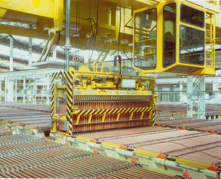
Copper is usually plated to a thickness of about 5 mm (40-60 kg each) over the course of 5-10 days. Much beyond this thickness and the mass becomes too great and the cathode may dislodge from the steel sheet under its own weight. (It is important that the copper not adhere too strongly to the cathode substrate, otherwise it would be too difficult to remove.) Copper plated onto copper starter sheets is plated to about 100 kg of mass. An average annual production rate is 50,000 tonnes per year. The largest plants produce about 100,000 t/y. Current efficiency is typically 85% - 95%. Typical energy consumptions are 1900-2000 kWh/t Cu (Jenkins et al. 1999, p. 493-567). Figure 5.3 shows photographs of a modern EW tankhouse.
Either a third or half of the cathodes are harvested from a cell at any given time. (Hence the number of cathodes per cell must be evenly divisible by three or two.) The rest remain in the cell so that it can keep operating (called live stripping) (Davenport et al. 2002). Cathodes are mechanically stripped from the steel sheets.
Cells are operated at 45-50°C solution temperature (Merigold 2009). This arises in part from the electrical resistance heating directly from the EW process. The electrolyte heated by the waste heat from electrolysis (solution resistance) is used to preheat incoming electrolyte (Pfalzgraff p. 217-221). Good control of temperature is important for obtaining smooth, dense deposits (fine-grained) (Jenkins et al. 1999, p. 493-567). It may be necessary to cool the lean electrolyte returning to stripping to minimize organic degradation reactions (Beukes and Badenhorst 2009, p.213-240).
Oxygen evolution at the anodes forms an acid mist when the gas breaks the surface. This is corrosive and toxic and much effort goes into controlling it. It also is a small loss of copper values. Control measures include polyethylene balls on top of the surface to promote coalescence, surfactants that produce a foam layer and prevent mist escaping and very good cross ventilation.
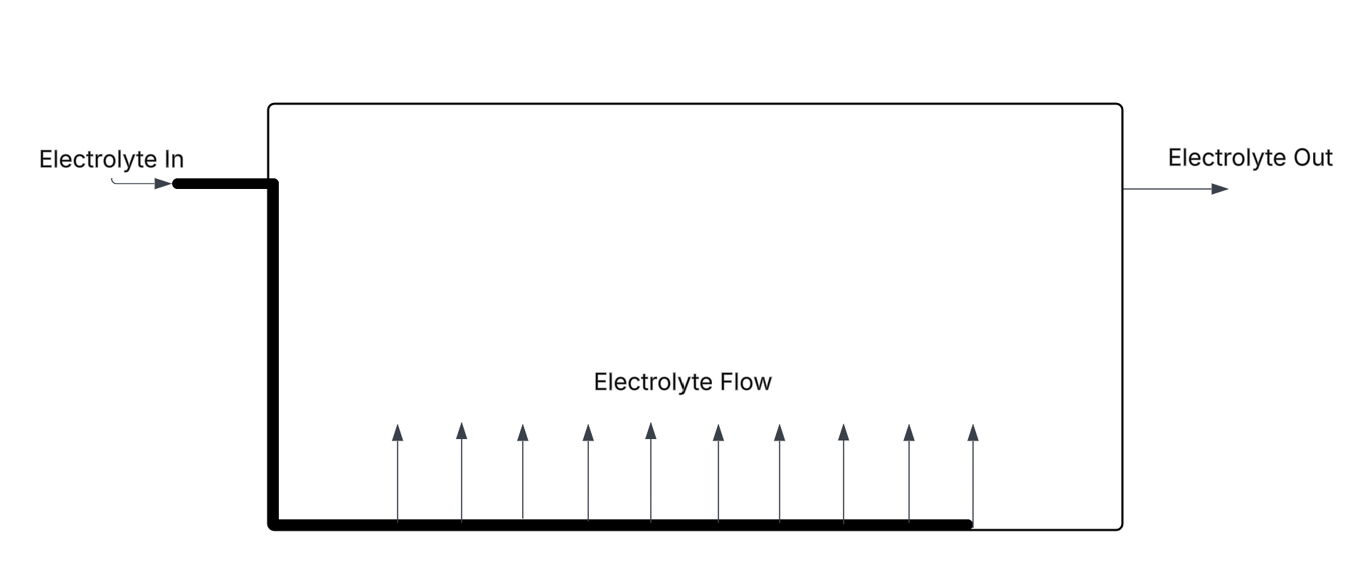
In many older plants electrolyte was introduced at one end of a cell and exited from the other without any deliberate agitation. Sometimes poor quality (rough) cathode deposits were formed. It was found that introducing the electrolyte via a distribution manifold led to consistently better cathode quality with the added advantage of allowing higher current densities (around 320 A/m2 at the plant where this was initiated) (Jenkins and Eamon 1990, p.41-56).
The manifold directs electrolyte flow upwards between the electrodes from all across the bottom of the cell. This is illustrated in Figure 5.4 below. A typical good flow rate is 0.12 m3/h/m2 of plating area (number of cathode faces x area per face) (Jenkins and Eamon 1990, p.41-56, Merigold 2009). The maximum is about 0.14 m3/h/m2 (Jenkins et al. 1999, p. 493-567) (too high and PbO2 particles can stay suspended). If the electrolyte flow into the cells from SX is too low to sustain this then additional recirculation pumps may be needed. Roughly half of the world’s EW plants in 1999 had electrolyte inlet manifolds (Hiskey p.169-186).
Strips or moldings or wax are placed on the edges of the cathodes to prevent copper plating on the edges (Jenkins and Eamon 1990, p.41-56). Plating on the edges would bind the cathodes on each face together, making cathode stripping difficult. Uneven current distribution at the edges produces dendritic growths and this copper is not readily recovered. Spacers are also used to keep anodes and cathodes from coming into physical contact. Another means of preventing contact is anode buttons (Beukes and Badenhorst 2009, p.213-240). These may be made of PVC and attached to anodes at the corners and in the middle. Spacers on various sorts keep a sufficient gap between anodes and cathodes so that exfoliating PbO2 does not as readily come in contact with the cathodes (Davenport et al. 2002).
Bleeding for impurity control
Inevitably impurities will build up in the EW electrolyte (Jenkins and Eamon 1990, p.41-56), whether by entrainment of aqueous solution in the loaded organic or chemical extraction. This occurs because the flow of electrolyte between EW and SX stripping is a closed loop. This leads to accumulation of iron especially, and depending on the ore being leached, also Cl-, NO3-, Mn+2 and others. Several of the deleterious effects of impurity elements have been mentioned previously. Removing impurities is commonly done by bleeding. A small fraction of the lean electrolyte is removed from the circuit (commonly 1-3% (Merigold 2009)).
As mentioned, in a good plant the Cu:Fe ratio entering the electrolyte from SX is 1000:1, i.e. the concentration of iron in the electrolyte is 1/1000 that of the copper, which is very good selectivity. If we take as an example 150 t/day copper production (54,750 t/year) the iron entering the electrolyte is 0.15 t/day. If the iron concentration that can be tolerated in the electrolyte is 2 kg/m3, the bleed rate can be calculated:
\[\frac{0.15~\text{t Fe/day} \times 1000~\text{kg/t}}{2~\text{kg Fe/m}^3}=75~\text{m}^3/\text{day}= 3.125~\text{m}^3/\text{h}\tag{119}\]
For instance, consider a 50,000 t/yr copper plant with ΔCu from SX = 10 g/L (difference between rich electrolyte and lean electrolyte [Cu+2]). The electrolyte flow rate then through EW is 571 m3/hr. The bleed rate then represents only about 0.55% of the electrolyte. Obviously this should be kept to a minimum. The higher the iron content that enters EW, the higher the bleed rate must be. Complete removal from the electrolyte by bleeding is not feasible; then the whole electrolyte would have to be treated. Then too a little iron has beneficial effects on cathode quality.
The bleeding process necessarily removes cobalt from the electrolyte. Since cobalt is quite expensive this adds a significant cost. Obviously, again, it is important to keep the bleed stream flow to a minimum. This is best achieved by having a very well operated SX plant to keep the Cu:Fe ratio high.
The bleed solution may be treated in a number of ways. It can be returned to leaching or to solvent extraction loading. The acid concentration is quite high, so it may have a mildly negative effect on extraction. Where iron, nitrate or chloride are at high levels in the PLS, the loaded organic may have to be treated to lower the impurities concentrations (Merigold 2009). Then another stage is added in SX prior to stripping. This is called scrubbing (Spence and Soderstrom p.239-257). High copper and somewhat higher acid than in the PLS can displace iron and with it Cl- or NO3-. Some of the bleed (diluted) can be used for this purpose.
An ion exchange process for iron removal (ferric only) from EW electrolytes is also available (Shaw et al. 2006, p.757-769). The resin selectively removes Fe+3. Once the resin capacity is saturated the resin is stripped using a Cu+2/Cu+/H2SO4 solution; then the resin can be reused. The great advantage is that no cobalt is lost from the electrolyte.
Plant configuration and electrolyte storage
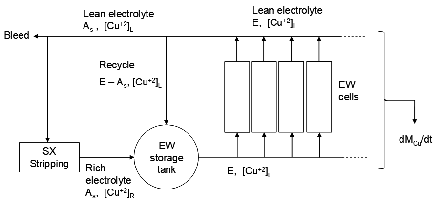
Rich electrolyte from SX goes into an electrolyte storage tank. The flows to and from this tank are shown in the figure below. It is common practice to split the lean electrolyte flow between storage and return to SX (Jenkins et al. 1999, p. 493-567). This is necessary because the change in copper concentration between rich and lean electrolytes may be greater than the change in copper concentration between the inlet and outlet of the cells. Note that electrolyte makes one pass through the cells and then is returned to stripping as lean electrolyte.
The fraction returning to SX ranges from 3-100% (100% means no splitting of the flow), but in most cases it is about 20-40% (Jenkins et al. 1999, p. 493-567). The storage tank provides for a consistent composition electrolyte in each cell in the EW plant. The copper concentration drops by 2-5 g/L as it passes through each cell. It depends on the total copper plating rate in the cell and the electrolyte flow rate through the cell. Also as noted previously, the specific flow rate of electrolyte to each cell should be around 0.12 m3/h/m2 plating area, at least when higher end current densities are used. The arrangement results in small change in copper concentration across the cell (about 2-3 g/L), ensuring that cathode quality is uniform across the cell. The copper delta for stripping (difference in copper concentrations for the rich and lean electrolytes) is often quite a bit higher (up to 15 g/L) (Jenkins et al. 1999, p. 493-567).
Note that the total mass flow through EW must equal the total mass flow through stripping due to mass balance. (We are omitting the lean electrolyte bleed at this point. When that is considered then mass flow through stripping = mass flow through EW + bleed.) However, the concentration changes through stripping and EW may differ significantly. This requires that the flow rate through EW (designated E) must differ from that through stripping. The mass flow through stripping is As ([Cu+2]rich elec. - [Cu+2]lean elec.), and this must equal the mass flow through EW, i.e. E ([Cu+2]into EW - [Cu+2]lean elec.). This in turn means that [Cu+2]into EW ≠ [Cu+2]rich elec.! Thus the rich electrolyte cannot be run directly into the EW cells! A flow configuration that accommodates these requirements is shown in Figure 5.5. The lean electrolyte exiting EW is used to dilute the rich electrolyte from stripping so that after passage through EW, its concentration equals that of the lean electrolyte.
The strip solution flow from/to SX is designated As m3/h. The rich electrolyte copper concentration is [Cu+2]R, and for the lean electrolyte it is [Cu+2]L. The difference in concentrations [Cu+2]R – [Cu+2]L = copper Δ. The electrolyte flow to EW is E and its concentration is [Cu+2]t. The change in copper concentration across the cell can be represented as Δ[Cu+2]tL. Designate the specific flow rate as fs.
The copper production rate is set by the net amount of copper taken up by the organic in extraction, all of which is transferred to the electrolyte during stripping. For a plant producing 50,000 t/y copper the hourly production rate is 5707.76 kg/h. Take as an example a rich electrolyte with 45 g/L Cu+2 and a strip copper Δ of 15 g/L. Then the lean electrolyte [Cu+2] is 30 g/L. The strip solution flow rate is then given by the copper production rate and the copper Δ:
\[A_s=\frac{\dfrac{dM_{\mathrm{Cu}}}{dt}}{\Delta[\mathrm{Cu}^{2+}]_{\text{strip}}}= \frac{5707.76~\text{kg/h}} 15~\text{kg/m}^3}=380.518~\text{m}^3/\text{h}\tag{120}\]
(mass per unit time / mass per unit volume). The copper production rate from equation {25} and equation {26} is:
\[\frac{dM_{\mathrm{Cu}}}{dt}=\frac{(j\,CE)\,(A_c\,N\,S)}{100\,nF}\;\cdot\;63.546\,\frac{\text{g}}{\text{mol}}\;\cdot\;
10^{-3}\,\frac{\text{kg}}{\text{g}}\;\cdot\;3600\,\frac{\text{s}}{\text{h}}\tag{121}\]
\[= 1.185499 \times 10^{-5}\,(j\,CE)(A_c\,N\,S)\;\text{kg Cu/h}\tag{122}\]
where Ac is the total plating area per sheet (both sides), S is the number of cells, and values for j, CE, Ac, N and S are to be chosen. Similarly, the flow rate to the cells, E, is given by the copper production rate divided by the change in copper concentration across each cell:
\[E=\frac{1.185499 \times 10^{-5}\,(j\,CE)(A_c\,N\,S)}{\Delta[\mathrm{Cu}^{2+}]_{tL}}\tag{123}\]
Ideally, the flow rate E should be such that the specific flow rate is 0.12-0.14 m3/h/m2 plating area. The total plating area is Ac N S. Then,
\[f_s=\frac{E}{A_c\,N\,S}=0.12\;\text{(or similar value)}\tag{124}\]
With these two equations we can solve for Δ[Cu+2]tL:
\[E=0.12\,A_c N S=\frac{1.185499 \times 10^{-5}\,(j\,CE)(A_c N S)}{\Delta[\mathrm{Cu}^{2+}]_{tL}}\tag{125}\]
\[\Delta[\mathrm{Cu}^{2+}]_{tL}=\frac{1.185499 \times 10^{-5}\,(j\,CE)}{0.12}\tag{126}\]
Take as an example j = 300 A/m2 and CE = 95%. Then for each cell,
\[\Delta[\mathrm{Cu}^{2+}]_{tL}=\frac{1.185499 \times 10^{-5} \times 300 \times 95}{0.12}=2.816~\text{kg/m}^3 \tag{127}\]
If fs is smaller, then the concentration change will be larger (lower flow, longer residence time for Cu+2 to be depleted). The mass balance for copper in Figure 5.5 is:
\[\frac{dM_{\mathrm{Cu}}}{dt}=A_s\bigl([\mathrm{Cu}^{2+}]_R - [\mathrm{Cu}^{2+}]_L\bigr)=E\bigl([\mathrm{Cu}^{2+}]_t - [\mathrm{Cu}^{2+}]_L\bigr)\tag{128}\]
Hence,
\[E=A_s\,\frac{\Delta[\mathrm{Cu}^{2+}]_{\text{strip}}}{\Delta[\mathrm{Cu}^{2+}]_{tL}}\tag{129}\]
\[E=\frac{350.518~\text{m}^3/\text{h} \times 15~\text{kg/m}^3}{2.816~\text{kg/m}^3}=2027.22~\text{m}^3/\text{h}
\tag{130}\]
Assuming a conventional cell with 60 steel cathode starter sheets, with 1 m x 1 m plating area per side, the number of cells then is given by using either equation {123} or equation {124}:
\[S=\frac{E}{A_c\,N\,f_s}=\frac{2027.22~\text{m}^3/\text{h}}{2~\text{m}^2 \times 60 \times 0.12~\text{m}^3/(\text{m}^2\!\cdot\!\text{h})}=140.8\tag{131}\]
There will be 141 cells in use. In a real tankhouse, there will be more cells in order to allow for downtime, maintenance and cleaning. (Typically the tankhouse is split in two, with a central cathode harvesting area. Then a tankhouse will have an even number of cells.) The nominal copper production rate will be:
\[1.185499 \times 10^{-5}\times 300\times 95\times 2\times 60\times 141\;\text{kg/h}=11433.2~\text{kg/h}=
50{,}078~\text{t/y}\tag{132}\]
The flow rates through EW will be:
As = 380.5 m3/h
E = 2027 m3/h
E – As = 1647 m3/h
The fraction of spent electrolyte going to SX stripping is:
\[\text{Fraction to SX}=\frac{A_s}{E}=18.8\%\tag{133}\]
The strip Δ[Cu+2] is 15 g/L (as specified) and the [Cu+2] from the tank to the cells is 32.8 g/L.
Higher current efficiency, higher current density and higher cathode surface area increase the copper plating rate in the cells. This necessitates a higher circulation rate through the cells (E). The lower the copper concentration drop across the cell, the higher the specific flow rate must be, and this too requires a higher rate of flow of electrolyte to the cells. However, there is a limit to how high the specific flow rate can be; too high and spalling PbO2 particles from the anodes may remain suspended in solution longer and contaminate the cathodes. Higher flow rates also incur greater cost for pumping. Sometimes there are two electrolyte storage tanks. Electrolyte clean-up processes may be conducted on solution flowing from the first tank (e.g. column flotation to remove entrained organic) (Miller et al. 1997, p.467-481). The lean electrolyte should probably not have <30 g/L copper. A high concentration is needed to allow for good quality copper plating at high current density.
Recent developments
Dimensionally stable anodes (DSA) have been in development for many years. As mentioned previously, these are composed of a titanium substrate coated with platinum-group metal oxides. They dramatically lower the oxygen evolution overpotential, which in turn lowers the applied voltage, and results in cost savings in energy utilization. Of course, the coatings are expensive. Nevertheless, the cost savings in energy consumption appear to more than compensate for the cost. Thus, there has been a move towards adopting DSA's into EW plants (Sandoval et al. 2010, p.1635-1647, Schlesinger et al. 2011, p.349-372). These anodes do not required CoSO4 addition either and labour and down time to clean lead corrosion sludge out of cells is no longer necessary, both of which are cost savings. Removing lead metal and compounds from the plant also improves worker health and safety.
Current densities of up to 450 A/m2 are being employed in some modern plants (Schlesinger et al. 2011, p.349-372). However, this will tend to produce rough, nodular deposits with consequent increase in short circuits and loss of current and energy efficiency. What is required is a decrease in the boundary layer thickness to steepen the Cu+2 concentration gradient and increase the limiting current density. (Recall that practical current densities are roughly 2/3 of the limiting current density.) Thus air sparging of the electrolyte in the cells is also practiced to improve mass transport of Cu+2 to the cathode surfaces. Another problem is that traditional additives used to promote smooth plating (guar derivatives) begin to break down more rapidly as current density begins to exceed 300 A/m2. This has necessitated development of new, synthetic additives. Maintaining evenly spaced and parallel cathodes and anodes is also increasingly important as current density increases.
There has been a move to add hoods or covers to copper EW cells (Schlesinger et al. 2011, p.349-372). These have been in use for many years in nickel EW plants where chlorine gas evolution occurs at the anodes. The gas is much too toxic to allow it to escape into the tankhouse and the atmosphere; it is also captured for use in leaching operations. In copper EW hoods are starting to be used to prevent acid mist accumulation in the tankhouse. This becomes all the more important at higher current densities and with air sparging. It obviates the need for foaming agents to reduce acid mist. Mists are directed to scrubbers. However, it also prevents manual inspection of the cells to look for problems. New types of sensors (such as online monitoring of cell temperatures and voltages) are needed to detect short circuits.
Media Attributions
- Ch7_F14_Cu_Cell_Electrode_Arrangement © Bé Wassink and Amir M. Dehkoda is licensed under a CC BY-NC (Attribution NonCommercial) license
- Ch7_F15_Cu_EW_Cell © Bé Wassink and Amir M. Dehkoda is licensed under a CC BY-NC (Attribution NonCommercial) license
- Ch7_F16_Copper_Tankhouse
- Ch7_F17_Electrolyte_Circulation_Manifold © Bé Wassink and Amir M. Dehkoda adapted by Jeno Hwang is licensed under a CC BY-NC (Attribution NonCommercial) license
- Ch7_F18_SX_EW_Flow_Electrolyte_Storage © Bé Wassink and Amir M. Dehkoda is licensed under a CC BY-NC (Attribution NonCommercial) license
