Chapter VII: Electrowinning
4. Electrowinning Fundamentals
After suitable solution purification a quite pure, concentrated electrolyte may be available for electrowinning. (In the case of copper, solvent extraction is the common method for solution purification.) Most commonly electrowinning is performed using sulfate solutions with oxygen evolution as the anodic half reaction:
\[\ce{M^{2+} + 2e- -> M}\qquad (\text{cathode})\tag{96}\]
\[\ce{H2O -> 0.5O2 + 2H+ + 2e-}\qquad (\text{anode})\tag{97}\]
\[\ce{MSO4(aq) + H2O(l) -> M(s) + 0.5O2(g) + H2SO4(aq)}\qquad (\text{overall reaction})\tag{98}\]
In such cases acid is generated during electrowinning. Electrowinning may also be carried out from chloride solutions in some instances. Then Cl- is oxidized to Cl2.
The electrowinning reaction for copper is,
\[\ce{CuSO4(aq) + H2O(l) -> Cu(s) + H2SO4(aq) + 0.5O2(g)}\tag{99}\]
The reduction reaction is:
\[\ce{Cu^{2+} + 2e- -> Cu}\qquadE^\circ = 0.34~\text{V}\tag{100}\]
The oxidation half reaction is the reverse of the oxygen reduction half reaction, i.e.,
\[\ce{1/2O2 + 2e- + 2H+ -> H2O}\qquadE^\circ = 1.23~\text{V}\tag{101}\]
\[\Delta E^\circ = 0.34~\text{V} - 1.23~\text{V} = -0.89~\text{V}\tag{102}\]
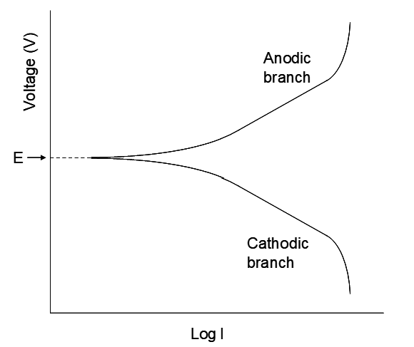
The reaction is not thermodynamically favourable, so energy must be supplied to make it go. The minimum energy required corresponds to the thermodynamic potential difference. In practice higher voltages are used to attain practical rates. The rate of metal plating is directly related to the current; the higher the current, the more e-/sec transferred, and the greater the metal plating rate. The nature of the relationships between the applied voltage and logI is illustrated in the figure below. This depicts the current-voltage relationship for a single half reaction. Of course another half reaction has to be at play as well; we cannot run a half reaction in isolation. However, the graph focuses on the log(current)-voltage graph for a single half reaction of interest. As the current approaches zero (logI → -∞) the cell runs increasingly slowly, approaching reversible behaviour. Then the measured voltage, in principle, corresponds to E, the half reaction potential, relative to some other half reaction (e.g. the standard H+/H2 half cell.) At this point a minute change in potential can reverse the direction of the half reaction (again, consistent with reversible behaviour). For the upper branch the oxidation occurs, e.g.
\[\ce{M_{(s)} -> M^{n+} + n e^-}\tag{103}\]
For the lower branch the reduction half reaction occurs, e.g.
\[\ce{M^{n+} + n e^- -> M_{(s)}}\tag{104}\]
A "three-electrode" cell can be used for this. The half reaction of interest occurs at a "working" electrode. The potential is measured relative to a reference electrode. The current is measured between the working electrode and a "counter" electrode.
It all depends on how the electrode is polarized (how the external potential is applied). Consider the cathodic branch. As the potential is decreased Mn+ is reduced. At first a substantial increase in reduction current results from relatively small decreases in applied voltage. Eventually a nearly linear region occurs, where logI is virtually linear with applied potential. This is called the Tafel region. Its slope is directly proportional to n, the number of electrons/mol of metal plated. (The form of the curves is well understood from electrochemical theory, but that is beyond the scope of this introduction.) The curve indicates that to obtain higher currents, higher voltages, beyond the reversible value E, are needed.
The Overpotential
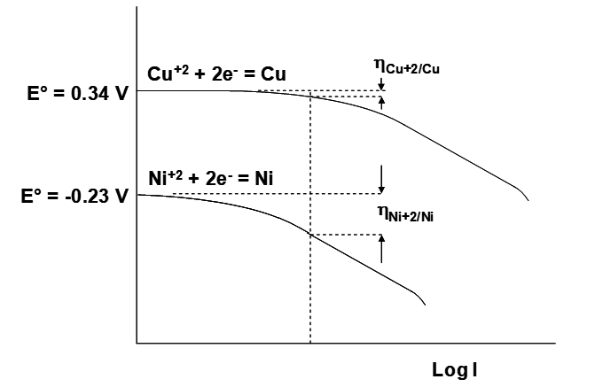
This leads to the idea of the overpotential. Overpotential (or overvoltage) is the additional potential needed beyond the thermodynamic potential E required to make the half reaction go at the desired rate. It is given the symbol η. As indicated earlier, the value of n will have a direct effect on how big the overvoltage is. For a given n value (2 for EW involving Cu+2, Ni+2, Co+2 or Zn+2), the shapes of the curves are often quite similar (there are subtle differences). However, what really matters is where the curves lie horizontally. This is illustrated in the figure below. The reduction of Cu+2 on Cu is considerably faster than the reduction of Ni+2 onto Ni. This appears as a shift of the Ni+2/Ni curve further to the left (to lower currents) relative to Cu+2/Cu. As a result, at a given current ηNi+2/Ni is greater than ηCu+2/Cu. This has implications for the energy consumption in electrowinning of the two metals. At a given current a greater overvoltage necessarily implies greater energy consumption. For electroplating simple metal aquoions three broad classes of processes must occur:
- Deformation of the aquocation complex as it approaches the metal surface and loss of coordinated water molecules.
- Electron transfer to the metal cation.
- Migration of the metal atom on the surface to a suitable crystallographic site.
Loss of water molecules may occur in concert with electron transfer. Each of these processes contributes to the overpotential; they all have an activation barrier, or energy hurdle that must be overcome. Sometimes one of these steps can be a major contributor to the overpotential.
The anode half reaction also has an associated overpotential. Oxygen evolution is the most common anode half reaction in electrowinning. This is ubiquitous in Cu, and Zn EW, and common for Ni and Co. Chloride oxidation to Cl2 is also employed in Ni EW. In gold EW from cyanide solution, the anode half reaction is oxidation of CN- to CNO-.
Oxygen evolution has some advantages:
- No additional costly reagents are needed; H2O is the reactant.
- Relatively less corrosive sulfate medium is suitable, and sulfate medium is the least expensive.
- Lead anodes may be used, which are inexpensive.
However, the main disadvantage is that it contributes to high energy consumption. First the E° for the O2/H2O half reaction is 1.23 V. This contributes to highly negative thermodynamic cell voltages:
\[\ce{Cu^{2+} + H2O -> Cu + 2H+ + 0.5O2}\qquad\Delta E^\circ = -0.89~\text{V}\tag{105}\]
\[\ce{Ni^{2+} + H2O -> Ni + 2H+ + 0.5O2}\qquad\Delta E^\circ = -1.46~\text{V}\tag{106}\]
\[\ce{Zn^{2+} + H2O -> Zn + 2H+ + 0.5O2}\qquad\Delta E^\circ = -1.99~\text{V}\tag{107}\]
In addition, water oxidation on most electrode surfaces is very slow. (This is an area of considerable economic and technical importance for fuel cell development too.) This results in a high anodic overpotential. Much work has gone into trying to find ways to lower the oxygen evolution overpotential as it is a significant factor in the operating costs of an EW plant. Lead has one of the highest overpotentials for oxygen evolution! However, lead is commonly used due to its low cost.
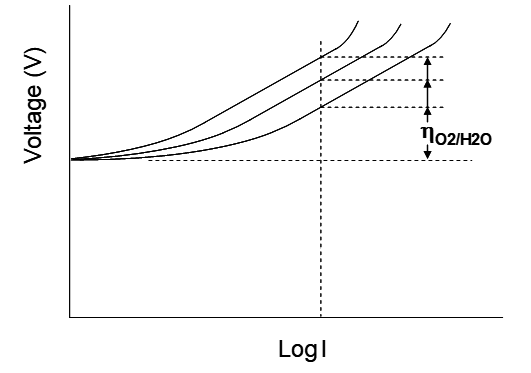
Lead anodes are commonly alloyed with minor amounts of other elements to try to lower the overvoltage. The intent is to shift the polarization curve further to the right. This is illustrated in the figure below. At 300 A/m2 current density the approximate O2 evolution overpotentials under different conditions are provided in the table below. The most common anode material in use today in Cu EW is a Pb-Sn-Ca alloy (~1.5% Sn, 0.1% Ca). There are numerous effects of solutes and alloy elements on anode performance and longevity. Calcium is added to increase strength. The anodes are cold rolled for the same reason. Tin lowers the oxygen evolution overpotential and improves corrosion resistance. There may be other effects as well. DSA anodes are of interest because the platinum group metal oxides used to coat the anodes (usually a titanium substrate) are very good at promoting O2 evolution.
| Table 4.1 - Oxygen evolution overpotentials from sulfuric acid solutions under several conditions at 300 A/m2 current density [2]. | ||
|---|---|---|
| Anode material | Other conditions | Overpotential (V) |
| Pb/Sb (e.g. 6% Sb) | ~0.7 | |
| Pb/Sb (6% Sb) | 100-150 mg/L Co+2 | ~0.6 |
| Pb/Ca(0.1%)/Sn(1.5%) 1 | ~0.6 | |
| DSA 2 | ~0.35 | |
1 Preferred due to better mechanical and corrosion properties compared with Pb/Sb.
2 DSA = dimensionally stable anodes; rigid titanium sheet or mesh coated with platinum-group metal oxides.
Cobalt addition is commonly practiced in Cu EW. It is believed that Co+2 oxidizes at the anode and catalyzes H2O oxidation [3]:
\[\ce{Co^{2+} -> Co^{3+} + e^-}
\qquad E^\circ = 1.90~\text{V} \; \text{(anode, very high!)}\tag{108}\]
\[\ce{2Co^{3+} + H2O -> 2Co^{2+} + 2H+ + 0.5O2}\tag{109}\]
Co+3 is a powerful oxidant and rapidly oxidizes water. It also lessens anode corrosion and improves stability of the PbO2 layer. However, cobalt is expensive. It is added at 100-200 mg/L, beyond which it has little beneficial effect.
Resistance losses
Conductors that carry electricity to the electrodes have an intrinsically low resistance. However, these extend over the length of the tankhouse and overall the resistance is enough to cause a moderate voltage drop. This is lost as heat. Likewise, contact between anodes and the current distribution conductors (busbars) and between cathode sheets and the busbars also has a resistance loss (contact resistance). This is necessary since anodes and cathodes must be removed (anodes in order to be replaced, cathodes for Cu metal harvesting). The other substantial resistance in the circuit is the solution resistance. In solution the current is carried by migration of ions. This allows for a complete circuit, without which there would be no current. Cations move towards the cathode (negatively polarized) and anions move toward the anode (positively polarized). Thus electrolyte conductivity is an important technical consideration in EW.
Ions in solution are capable of conducting electricity. (This was one of the key observations that lead scientists to conclude that some compounds were comprised of discrete cations and anions.) A strong electrolyte is a salt that is soluble in water and which fully dissociates into ions. Ions vary in their ability to conduct electricity (per unit concentration). The hydrogen ion, H+, is by far the best conductor, followed by OH-, then other cations. H+ is at least 3 times more conducting (per unit concentration) than other cations. Thus the presence of H2SO4 in the electrolyte is quite beneficial. Copper EW electrolytes contain on the order of 180 g/L H2SO4. Much beyond this and corrosion of the steel starter sheets and other parts of the plant becomes problematic.
The reason is believed to be due to the "proton jump" mechanism. H+ is present as H3O+. An H+ in an H3O+ ion can "jump" to a neighbouring water molecule as shown below. This allows it to move through solution much more rapidly than the diffusion or migration of other ions. The same mechanism may be in effect for OH-, though it is somewhat less effective, as indicated by its lower conductance.
EW is operated at constant current, so based on Ohm's law the voltage drops due to resistance losses can be summed up:
\[V_{IR} = I \sum_i R_i\tag{110}\]
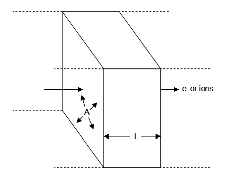
The resistance of a resistor is a function of its geometry and its inherent resistivity (the resistance of a standard geometry). The longer the distance through which the electrons (or ions) must travel, the greater the total resistance; R ∝ L where L = length. The greater the cross sectional area of the resistor, the more current it can support (more pathways for electrons/ions to move through). Hence R ∝ 1/A where A is the cross sectional area. Then,
\[R \propto \frac{L}{A}\tag{111}\]
and
\[R = \rho\,\frac{L}{A}\tag{112}\]
where ρ = resistivity. This is illustrated in the figure below. Thus in EW large surface area electrodes are used with a minimum practical spacing between cathodes and anodes. Limitations on these features are discussed later. Clearly the lower the resistivity the better. Thus a more concentrated solution of ions, and where feasible, high concentrations of H+ are desirable. In electrowinning of divalent metal ions from aqueous solution there is a complicating factor and that is ion pairing. This essentially the formation of a complex, e.g.
\[\ce{M^{2+}(aq) + SO4^{2-}(aq) -> MSO4(aq)}\tag{113}\]
The extent to which this happens depends on the metal ion, temperature and pH; recall that SO42- is also a weak base and may form HSO4- as well. A neutral ion pair does not contribute significantly to the conductivity of the solution.
Some example data for simple CuSO4-H2SO4 electrolytes are shown in Table 4.2. Note that for a given acid concentration (50°C column) the resistivity increases with increasing [Cu+2], i.e. [CuSO4] (as well as decreased [H+] due to formation of HSO4-), while higher acid concentrations lower the resistivity. Iron is also commonly present in copper EW electrolytes at concentrations of up to 5 g/L. It will be present in its two common valence states: Fe+3 and Fe+2. This also will affect the resistivity of the electrolyte. It is also common to consider the inverse of resistance or resistivity instead. The inverse of resistance is conductance. The specific conductance is 1/ρ in Ω-1cm-1. Now higher conductance (lower resistance) is desirable.
| Table 4.2 - Illustrative example data for resistivity of simple CuSO4-H2SO4 solutions at different temperatures [4]. | ||||
|---|---|---|---|---|
| Cu+2 g/L | H2SO4 g/L | Resistivity Ω cm | ||
| 30°C | 40°C | 50°C | ||
| 25 | 71.7 | 3.75 | 3.52 | 3.26 |
| 35 | 143.4 | 2.29 | 2.09 | |
| 35 | 191.2 | 1.92 | 1.74 | |
| 40 | 163.4 | 1.50 | ||
| 40 | 182.6 | 1.42 | ||
| 50 | 163.4 | 1.71 | ||
| 50 | 182.6 | 1.57 | ||
| 55 | 163.4 | 1.76 | ||
| 55 | 182.6 | 1.63 | ||
| 60 | 167.3 | 2.37 | 2.15 | |
As an example, take the cathode-anode gap to be 4.8 cm, and the immersed plating area of 1.2 m2 (100 cm x 120 cm). A typical electrolyte might contain 40 g/L Cu+2, 180 g/L sulfuric acid and have an operating temperature of 50°C (although there may be a significant range of conditions in practice). The corresponding resistivity then is about 1.42 Ωcm. The resistance then is:
\[1.42~\Omega\!\cdot\!\text{cm}\;\times\;\frac{4.8~\text{cm}}{12000~\text{cm}^2}\;=\;5.68\times10^{-4}~\Omega \tag{114}\]
The voltage drop across the resistance is V = IR. For a 300 A/m2 current density,
\[0.000568~\Omega \;\times\; 1.2~\text{m}^2 \;\times\; 300~\text{A/m}^2\;=\;0.204~\text{V}\tag{115}\]
The four contributions to applied cell voltage
Putting the pieces together we have the following relationship for the applied voltage:
\[\Delta E_{\text{applied}} = -\Delta E\;+\;\eta_C\;+\;\eta_A\;+\;I \sum_i R_i\tag{116}\]
The first term is the thermodynamic potential (ΔE is negative and must be opposed). Next are the two overpotentials. The last term is the sum of the IR voltage drops. Note too that increasing the current increases this term. Likewise the overpotentials are a function of current (or current density). -ΔE is constant for a given electrolyte composition and changes only a little through the cell as metal is plated. Ballpark estimates for the four terms in copper EW are given below:
- -ΔE ~ 0.9 V
- Anodic overpotential (ηA) ~ 0.5 V (depends on current density)
- Cathodic overpotential (ηC) ~ 0.1 V (depends on current density)
- I∑Ri ~ 0.5-0.6 V (depends on current); solution resistance ~0.3 V and rectifier + cell hardware resistances ~0.2 V (The rectifier converts AC power to DC power.)
Total applied voltage ~2V in the example above. Depending on the source cited, there is some variability in values quoted for solution resistance and cell hardware resistances. However, a total voltage drop dues to resistance losses of up to 0.6 V or so is typical. In general industrial plants employ cell voltages of 1.8-2.2 V. Note that this significantly exceeds -ΔE. The actual cell voltage (measured between anode and cathode) and the total applied voltage (including the power source and current distribution network) may differ somewhat, depending on whether the hardware and rectifier resistances drops are included or not. In the end, what matters is the total applied voltage and the total current. This is what determines the energy consumption and associated cost.
Limiting and practical current densities
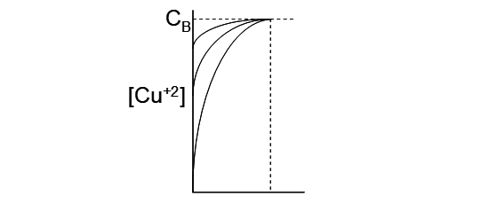
From Faraday's law and related relationships, it is clear that plating at higher current densities is desirable; for a given plating surface area production increases with increasing current density. However, there are two important limitations. The first is a fundamental limit. Referring back to Figure 4.1, at higher currents the polarization curves start to approach infinite slope (tend toward vertical lines). As metal ion is plated, the concentration drops near the surface, relative to the bulk concentration. This creates a concentration gradient, which induces mass transport of Mn+ towards the cathode. The greater the plating rate, the bigger the concentration drop, i.e. the lower the concentration at the surface. This is illustrated in the figure below. At some critical current density the concentration of metal ion at the surface goes to zero. This is the diffusion limited current and represents the maximum current that can be sustained under the given conditions. At this point the polarization curve approaches infinite slope. Further increases in current cannot be sustained by Mn+ reduction. Then the next available half reaction will begin to occur. Reduction of H+ to H2 may then occur, for which ΔE° = -1.23 V. An increase in the applied voltage then would also necessarily occur (at constant current). This wastes electricity and would never be attempted in a normal electrowinning situation. For copper EW the diffusion limited current density is about 500 A/m2 [5].
In practice significantly lower current densities are employed for conventional EW. This is related to a practical limitation. At very high plating rates the copper atoms deposited on the cathode surface do not have time to migrate to a suitable crystallographic site. The net result is that large numbers of new crystals form on the surface, rather than growing existing crystal faces. This makes for very crumbly deposits that adhere very weakly to the cathode surface, making cathode harvesting difficult and costly. Fine grained copper particles would spall off the cathode and have to be collected, filtered and washed. At lower, but still too high plating rates too many crystals are still forming; the deposit may be more adherent, but it will be porous as crystals grow together rapidly and trap solution between their faces. This will increase the sulfur (from electrolyte sulfate), oxygen (from water, etc.), iron, etc. impurities content in the cathodes and make them off-spec. Thus in conventional copper EW maximum current densities are about 350 A/m2 [6].
The 500 A/m2 limiting current density is for a solution without intentional agitation. The vertical line in Figure 4.5 demarcates the point closest to the electrode surface where the solution metal ion concentration is equal to the bulk solution concentration. This is called the boundary layer. If the boundary layer is made thinner by agitation then the concentration gradient steepens and higher limiting (and practical) current densities are possible. However this requires energy. A typical Cu EW tankhouse may have several hundred cells, each with as many as 60 cathodes and 61 anodes, closely spaced together. Agitation then becomes difficult. However, if electrolyte is directed up between cathodes and anodes using a header, this can impart some additional agitation allowing current densities to be at the higher end of the practical range. The minimum thickness of the boundary layer is about 0.01 mm, which requires intensive agitation [7] and is not achieved in EW.
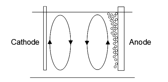
There are two features in an EW cell that result in a measure of natural agitation (actually convection) [5]. At the anode surface oxygen gas is evolved. This gas pushes up solution as it rises. The bubbles accumulate at the surface before rupture. Overall this displaces solution in an upward motion in the vicinity of the anode. At the electrode surface Cu+2 is depleted, lowering the [Cu+2] and decreasing the solution density. This causes solution to naturally rise near the surface of the cathode. The net result is two counter-rotating loops, as shown in the figure below, which also helps to thin the boundary layer near the cathode surface. The boundary layer thickness achieved by this natural convection is about 0.1-0.2 mm [7]. Directing electrolyte up between electrodes using a header further thins the boundary layer, though not to the limit of ~0.01 mm.
Current distribution and protrusions
Anodes and cathodes are large plane sheets that are kept parallel. This promotes a uniform distribution of the electric field over the surfaces (other than at the edges). This in turn promotes uniform plating rate over the surface, which is important for growing a smooth, compact deposit. This lowers porosity and helps prevent occlusion of electrolyte with the attendant increase in impurities in the deposit. However, deposits are polycrystalline and surface roughness will eventually develop. Then there are high and low spots on the surface.
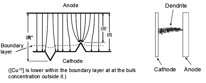
Electric field lines tend to converge at points and diverge at depressions. This leads to the situation shown in the diagram below. This makes the tips grow faster and the depressions grow slower, further increasing surface roughness and promoting growth of protrusions. Further, the high points are closer to the anode and the depressions are further away, decreasing the IR voltage drop due to solution resistance for the high points and increasing it for the depressions. Finally, high points extend out into the boundary layer where the [Mn+] is higher, making electroplating easier. All totaled these effects can result in more rapidly growing protrusions. As these extend further out from the surface their growth rate increases. Then a polycrystalline agglomeration of copper called a dendrite will extend out towards the anode, eventually making contact and causing a short-circuit. At this point all the electrical energy in the cell is lost as heat. The current follows the path of least resistance through the short circuit, rather than through the solution to plate copper. This in part acts to limit how close cathodes and anodes can be to each other.
Plant operators take pains to minimize this problem. This can be done by using "leveling" agents. These are often complex chemical mixtures that act by selectively adsorbing on the fastest growing sites. This increases the resistance of the protrusion and helps slow down their growth [8]. It is common practice to use infrared scanners to detect hot spots in cells where a short circuit has occurred. An operator will then go to the cell and use a bar to dislodge the dendrites to resume plating.
Another approach to controlling surface roughness is periodic current reversal (PCR). The polarity of the cathodes and anodes is switch briefly at frequent intervals. The copper electrode now becomes the anode for a short time. The protrusions being the most active sites, as indicated above, are most rapidly oxidized, dissolving them. This effectively prevents growth of protrusions on the cathode surface. Copper metal will plate on the lead electrode, briefly, but this will again be completely oxidized off. The duration of the polarity switch is brief. This may obviate the need for addition of leveling agents and associated costs, however, it does cost electricity.
Media Attributions
- Ch7_F7_Half_Reaction_Polarization_Curve © Bé Wassink and Amir M. Dehkoda is licensed under a CC BY-NC (Attribution NonCommercial) license
- Ch7_F8_Cu_Ni_Reduction_Branches © Bé Wassink and Amir M. Dehkoda is licensed under a CC BY-NC (Attribution NonCommercial) license
- Ch7_F9_OER_Polarization_Curves © Bé Wassink and Amir M. Dehkoda is licensed under a CC BY-NC (Attribution NonCommercial) license
- Ch7_F10_Conductor_Resistance © Bé Wassink and Amir M. Dehkoda is licensed under a CC BY-NC (Attribution NonCommercial) license
- Ch7_F11_Metal_Plating_Concentration_Profile © Bé Wassink and Amir M. Dehkoda is licensed under a CC BY-NC (Attribution NonCommercial) license
- Ch7_F12_EW_Cell_Natural_Convection © Bé Wassink and Amir M. Dehkoda is licensed under a CC BY-NC (Attribution NonCommercial) license
- Ch7_F13_Protrusion_Depression_Effect © Bé Wassink and Amir M. Dehkoda is licensed under a CC BY-NC (Attribution NonCommercial) license
In the context of electrochemistry, the driving force for electrons to transfer from one species to another under specified conditions of temperature, pressure and composition (concentrations, or, better, activities). The units are volts. When a charge of 1 C passes through a potential difference of 1 V energy equal to 1 J is released or consumed (depending on whether the charge flows with or against the electric field). By definition, 1 J º 1 VC. The standard cell voltage (see "standard conditions") is designated △E°. For non-standard conditions, it is designated △E.
