Chapter IV: Introduction to Leaching
5. In Situ Leaching
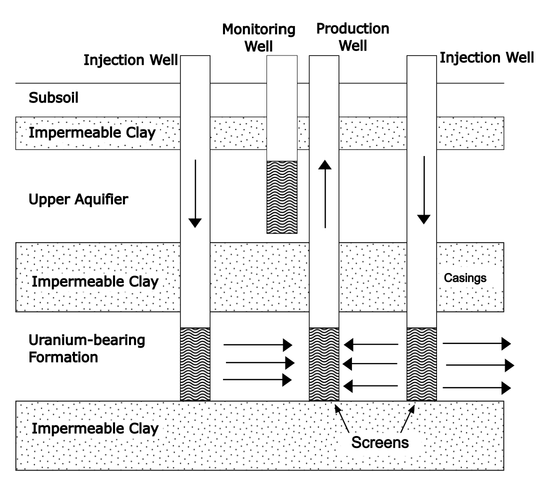
In situ is Latin for “in position.” In terms of ore handling, this is the simplest of all leaching methods (not indicated in Figure 4.1). The ore is not actually mined. Rather, a leach solution is pumped down into a rock formation (e.g. sandstone) at various points and then solution is pumped back up to the surface at others. If the ore body is not sufficiently porous, blasting may be used to rubblize it first.
This method of mineral extraction has long been used to recover soluble salt deposits deep under ground. These are termed evaporate deposits. Application to other minerals requiring more aggressive chemicals is more recent. This method has been used for uranium and copper production. On the one hand, it is quite simple since the ore rock is not removed from the ground. What is complicated about in situ leaching is the solution flow through the ore and the presence of natural aquifers. If leach solutions mix with an aquifer and flow out from the area, that water will be contaminated with toxic chemicals. While metal values would be lost, the former concern is by far the greater. A thorough knowledge of the hydrology of the area is, therefore, essential. In illustration of an in situ leach system for uranium is illustrated in Figure 5.1.
Dump and Heap Leaching
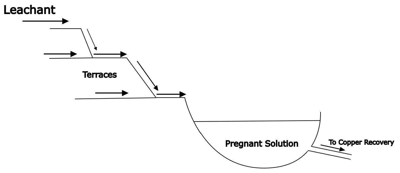
These methods are similar in that ore is mined and removed from the mine, then piled up and treated with leach solution from the top. Solution works its way down through the material and dissolves the minerals of interest and some gangue minerals. Solution is collected from the bottom and processed for metal recovery. Dump leaching is rather cruder, though, than heap leaching, as the word implies. Dump leaching is applied to rejected ore, e.g. from an open pit mine, that has a grade that is too low for the main process in use and to oversize ore from the mine that cannot be crushed. Thus dump leach ore rock may exceed 1 m in size. Dump leaching is a way to economically extract some value from what is otherwise waste material. Dumps are located on natural slopes and leach solutions flow to a natural drainage basin. There is minimal or no site preparation. Dumps may contain millions of tones of ore, cover up to hundreds hectares and may be >100 m deep. A schematic illustration of a copper dump leach is shown in Figure 5.2. Recoveries are modest, typically about 60%.
Heap leaching has been in use for more than 500 years. An early citation (1557) refers to a heap leach operation where alum, i.e. Al2(SO4)3·18H2O, was recovered for use in the textile industry (cloth dying). Much more care and effort goes into a heap leach than a dump leach. Optimizing economic extraction is a key goal. Heap leaching may use mined ore without further size reduction (run of mine ore; ROM), but often it is first crushed to some prescribed size range. These days, heap leaching is commonly practiced for gold, copper and uranium extraction. Research is going on in order to extend it to nickel, zinc, etc.
Heap leaching, in contrast to dump leaching, uses a carefully constructed base or pad. Ideally, the site is graded to a slope of about 1%. A heavy duty plastic liner is placed on the base and ore is piled onto this. The slope drains towards a collection trough along the edge of the heap to collect PLS. Again solution is applied
to the top of the heap, which is leveled. A number of methods may be used. Large-scale sprinklers are used, as well as drip emitters. The latter involves a network (usually on a 1 x 1 m grid spacing) of tubing where solution drips directly onto the heap surface. These are good for minimizing water loss by evaporation and misting. A pond for storage and surge capacity is built downstream of the collection ditch. PLS is processed for metal recovery and the barren solution is then redirected back to leaching. Make-up reagents are added as needed. A schematic illustration is shown in Figure 5.4. A heap leach may pad may be kilometers long, hundreds of meters wide and >100 m high. It will contain millions of tones of ore, mined at a rate of 10,000-500,000 tonnes/day. The time frame for heap leaching a given ore runs from weeks to years. Typical extraction efficiencies are moderately good; about 80%.
Copper heap leaching has been practice since about 1700. Gold heap leaching began around 1969. Most of the world’s hydrometallurgical copper production is obtained from heap leaching operations. The biggest facility in the world is in Chile and produced 145,000 tonnes of copper in 2010. A gold leach with as little as 0.5 g Au/t ore (0.5 ppm!) can be profitable. Even some high grade gold ores with about 15 g Au/t ore are being successfully heap leached. Roughly 12% of the world’s annual gold production comes through heap leaching. An average gold heap leach operation produces about 5 tonnes Au/year (about 160,000 oz).
For gold extraction, heap leaching is often compared to agitated tank leaching. The latter requires finely ground ore and energy-intensive agitation to suspend ore particles and provide efficient contact with the leaching solution, in large tanks. All of this adds considerably to capital and operating costs for extraction. Heap leaching economics are often more favourable.
There are a number of important factors in the design of a heap leach. Extensive laboratory testing, including using columns of ore, are devised to determine suitable parameters. Some of the main factors are discussed below.
Leaching Chemistry
Copper ores are typically heap leached when a concentrate cannot be made. This may occur in the case of low-grade Cu ores (e.g. <0.5% Cu) or when other factors preclude making a concentrate, for example, oxidized ores cannot be easily concentrated. Oxidized copper minerals (like CuO, CuSiO3·nH2O, Cu2CO3(OH)2, etc., are readily leached in dilute sulfuric acid. Gold/silver ores are leached with dilute cyanide solutions and also require oxygen. The oxygen solubility in water from air is often sufficient for this purpose. A sulfide ore containing minerals such as CuS, Cu2S and Cu5FeS4 requires oxidizing conditions as well as sulfuric acid. Bacteria are generally used (thiobacillus thiooxidans, etc.) and the leach also requires oxygen. The sulfide portions of the minerals are ultimately oxidized to sulfate, solubilizing the metal ions. However, the higher concentrations of minerals of interest means that oxygen from solution added to the top of the heap will be depleted well before the bottom of the heap is reached. Provision for blowing air up through the heap is then needed. Note that chalcopyrite, CuFeS2, is not readily amenable to heap leaching. This mineral passivates soon after leaching begins, possibly due to the formation of an impervious and unreactive intermediate sulfide layer. Recoveries of copper from bioleaching, or conventional ferric ion leaching are poor. If at all possible, chalcopyrite and other copper sulfide minerals are concentrated and then smelted. Other sulfide minerals may also be dissolved to some extent. Pyrite, FeS2, will be readily oxidized by the bacteria. This may result in net acid production, whereas many other minerals will consume acid. Where net acid is produced it may be necessary to implement partial neutralization, which requires base and added expense.
Ore Size
An important issue in heap leaching is how finely the ore must be crushed in order to obtain good extraction. Finely crushed ore may be more rapidly extracted and perhaps to a higher degree, but this costs more. The enhanced extraction must be sufficient to justify the extra cost. This ends up being a trade-off between economics and technical possibility. In some cases the mined ore itself (run of mine ore; ROM) is leached directly without size reduction. In other cases the ore is crushed, even to the extent of using secondary cone crushers. If much fine material is generated by size reduction, or if the ore contains a lot of clay minerals, agglomeration may be needed. Otherwise the fine material may plug the heap and render it impervious to solution flow. Often this involves rolling the ore inside a large drum, with suitable reagents that bind the small particles. For gold ores this may involve small additions of cement. For copper ores strong sulfuric acid solutions are often used, particularly with oxidized ores. This acts to cause small particles to stick together through modification of silicate mineral bonds. This has the double effect of combining fine particles into porous agglomerates and jump-starting the leaching process. Alternatively, clay minerals can be separated out by screening. The physical nature of the ore has many important implications for heap leaching.
Heap Permeability and Solution Flow
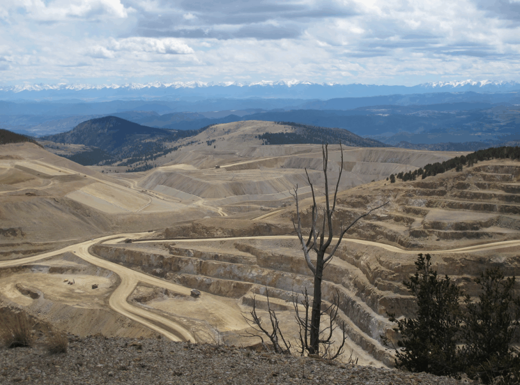
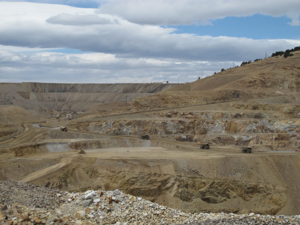
This is a complicated business and complex models have been developed for understanding and predicting solution flow through heaps. Lab testing is needed to determine how deep a heap can be. Efforts are made to maximize heap leach heights in order to minimize the operation’s footprint and effects on the environment. Heaps may be built in single layers (each layer is called a “lift”) or in multiple layers. Lifts may vary in depth, but on the order of 10 m is typical. Heaps with multiple lifts may reach heights in excess of 100 m. Here again the nature of the ore becomes very important. Compaction of lower lifts may impede solution flow. Also, with increasing height, it takes longer for fresh PLS solution from the upper lift to exit the heap at the base. A photo of a copper heap leach with four lifts is shown below (Figure 5.5).
Stacking Procedures
There are two broad classes of ore stacking on heaps: truck stacking and conveyor stacking. The physical characteristics of the ore and the rate of stacking are important considerations. For a number of reasons smaller operations (10,000-50,000 tonnes of ore per day) may more economically use conveyors. For ~100,000 t/d truck stacking is often preferred. For very large operations, stackers mounted on caterpillar tracks are used. A photo of conveyor stacking equipment is shown in Figure 13.
Percolation Leaching
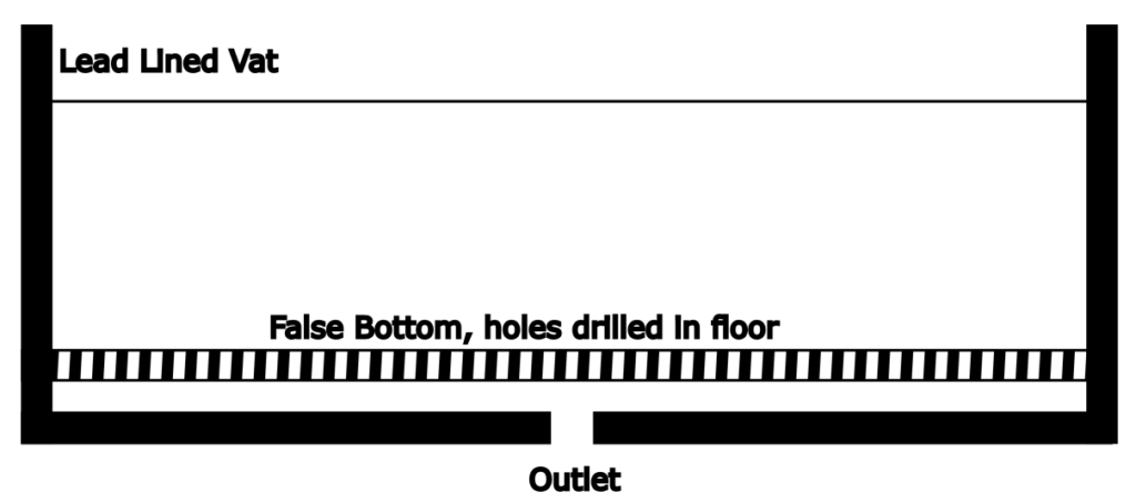
This is also known as vat leaching. A relatively low grade ore is crushed to about 5-20 cm particle size and loaded into large tanks. Fine material is removed, or possibly treated to agglomerate it. (As in heap leaching, fine material will plug the tank bottom and also slow down solution flow through the ore mass.) The bottom of the vat is often designed to be permeable to solutions. The vats are, in effect, very large filters. They are usually made of concrete and line with lead or wood. Capacities may be up to 104 m3, with a bed depth of up to 6 m. The largest vats contained up to 12,000 tonnes of ore. Vats are filled and emptied mechanically, which involves high labour costs; the technology is prohibitively expensive in the developed world.
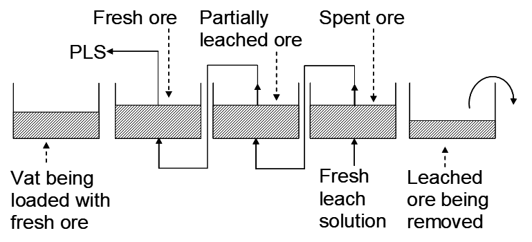
A series of vats may be used with solution flowing in essentially counter-current fashion. This is illustrated in Figure 5.5. Fresh (and the most aggressive) leach solution first contacts the most leached ore, which obviously still contains the minerals that are hardest to leach. This affords the greatest driving force to most fully leach the ore. On the other hand, the freshest ore contacts the most depleted leach solution. However, the minerals that are easy to leach react easily with the remaining leaching reagents. This ensures that reagents are well utilized. For instance, if it is acid being used to leach an oxidized copper ore, then the weaker solution contacting the fresh ore has a better chance to be used up. This is economically favourable, especially when excess reagents have to be removed prior to metal recovery steps.
Figure 5.6 shows details of what a percolation tank looks like. Solution may be passed down through the ore or up. Upflow has the advantage of immersing the ore charge in leach solution, allowing for better contact between ore and solution and more efficient leaching. It may also minimize plugging of the bottom of vats. However, upflow of solution precluded use of air as an oxidant, so the technique was limited to oxide copper ores. While ore in some vats is being actively leached, other vats may be emptied of spent ore, and other vats loaded with fresh ore. While counter-current operation provided for high extraction efficiency (up to about 90%), vat leaching has been largely displaced by heap leaching, which is easier to operate, much more economic and suited to much larger scale.
-
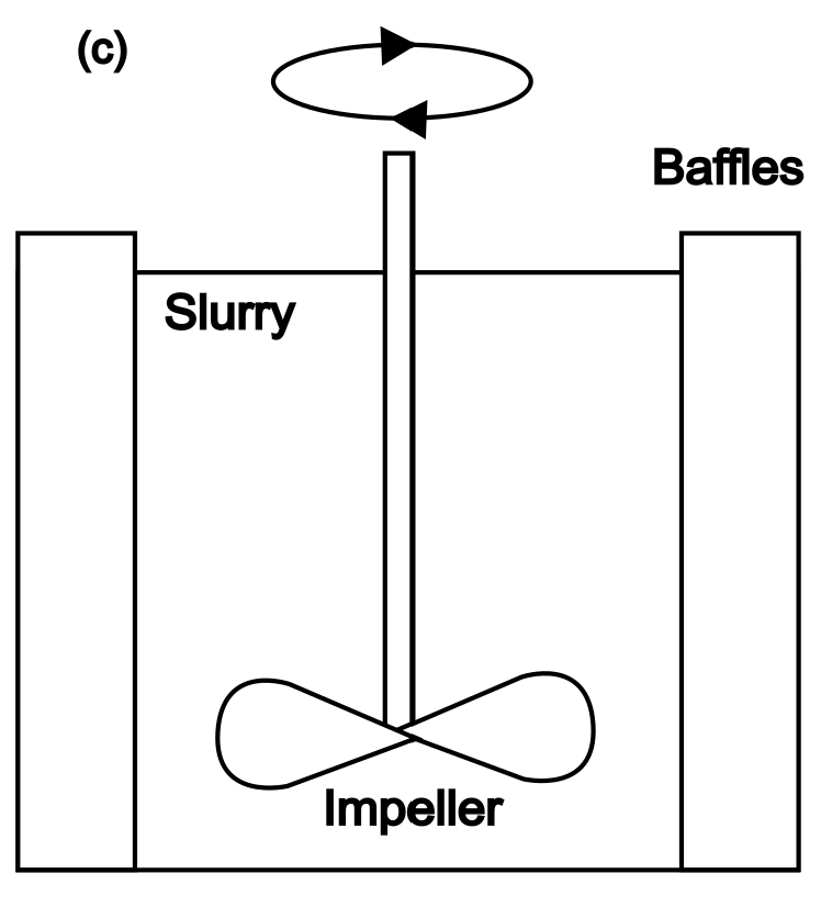
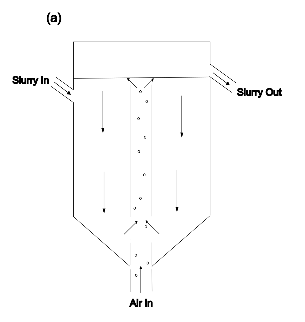
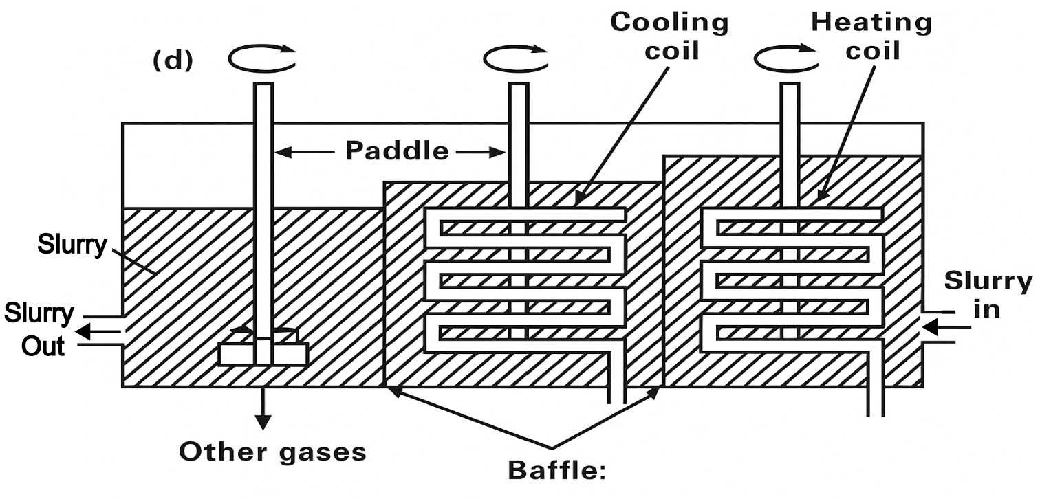
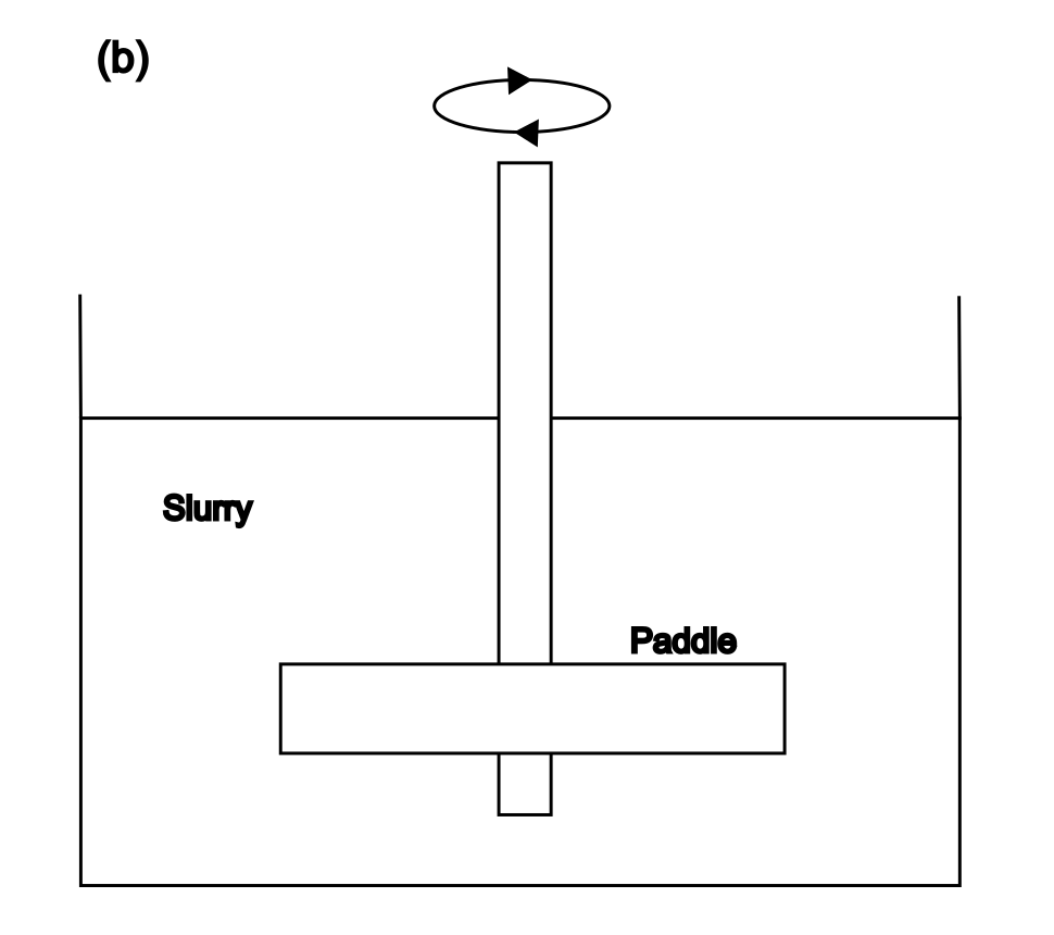
- Figure 5.7 – Types of vessels used in agitation leaching. (a) Pachuca tank, (b) low speed agitation, (c) high speed agitation, and (d) pressurized, agitated autoclave.
Agitation Leaching
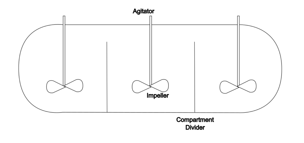
There are numerous types of agitated leaching systems. The common thread is that ore is ground to small particle size (commonly on the order of 10-200 μm) and suspended in a leach solution. Extensive size reduction adds to costs, but is necessary to be able to achieve suspension. Both suspension in the slurry and high particle surface area are necessary so that reactions are fairly rapid (minutes to hours). The vessels and associated infrastructure are expensive and so maximizing reaction rate minimizes required residence time, and hence equipment size and cost. Understandably then, agitation in leaching involves an increase in capital and operating costs. This is justified under various conditions: when the ore has high value (moderate to high grade); metal values are finely disseminated in the ore and fine grinding is required to effect mineral exposure. Other forms of leaching then are not applicable since the ore is too fine now. Reactors may be operated in batch mode or continuously. Continuous operation is more efficient. Examples of four types of vessels are outlined in Figure 5.7.
Pachuca Tanks
These are named after a small mining town in Mexico where they were first used. Pressurized air is blown up through slurry in a tall tank. The upward motion causes slurry to be drawn up. A circulation pattern results as shown in the figure. A central air lift tube may or may not be present. Reactors may be operated in batch mode or slurry may be fed in continuously. Where oxygen is consumed agitation also provides for dissolution of air in the solution. The air line may also come in from the top and discharge near the bottom. Live steam (steam directly in contact with the slurry) introduced with the air may be used to heat the slurry up to 70°C without difficulty. Tanks are typically 3.5 m across, 14 m high and have a 60° conical bottom. They may be made of wood, steel or rubber-lined steel. These reactors operate at close to ambient pressure. Several reactors in series may be required to achieve the required total residence time. They are used for acid leaching of oxide minerals and for cyanide leaching of gold. One problem with these is re-suspending the solids after a power failure or shutdown. It is an old technology which is falling out of favour.
Low-Speed Agitated Leaching
These are used when high turbulence is not required. These provide off-bottom suspension. Large diameter rakes or paddles may be used. This is suitable when the reactions involved are relatively slow and not improved by intense mixing.
High-Speed Agitated Leaching
These are used when the chemical processes are fast and limited only by diffusion of reagents to the mineral surface. (Upon contact the reactions occur; they are fast.) Very good mixing is required to constantly replenish the reactants at the mineral surface. Otherwise the reaction would be slowed by having to wait for reactants to diffuse through solution toward the mineral surface. The agitator is designed to pump slurry around rapidly. High power impellers are used. Depending on the application, varying levels of shear may be required. The shape of the impeller or turbine is quite important. Impellers designed for shear and flow are discussed later in these notes. An example of where shear is needed is when air or oxygen has to be introduced. Shear breaks up the gas flow into fine bubbles that have high surface area and that are more rapidly absorbed by the leach solution. Baffled tanks are employed to prevent the slurry from simply spinning around (vortexing) with diminished efficiency of mixing. (This is treated in a bit more detail in the section on agitation.) This type of leaching is often required when redox reactions are employed (such as oxidation of sulfide minerals). Atmospheric pressure tanks are suitable for temperatures below 100°C. Bacterial leaching of copper sulfide concentrates is an example of where an agitated tank leach is used.
Media Attributions
- Ch4_F8_Uranium_Mining © Bé Wassink and Amir M. Dehkoda adapted by Jeno Hwang is licensed under a CC BY-NC (Attribution NonCommercial) license
- Ch4_F9_Copper_Ore_Dump_Leach © A.K. Biswas and W.G. Davenport adapted by Jeno Hwang is licensed under a CC BY-NC (Attribution NonCommercial) license
- Ch4_F11_Heap_Leach_Pad_Cresson_Pit © Bé Wassink and Amir M. Dehkoda is licensed under a CC BY-NC (Attribution NonCommercial) license
- Ch4_F12_Truck_Stacking_System © Kelly Michals is licensed under a CC BY-NC (Attribution NonCommercial) license
- Ch4_F13_Percolation_Leaching © Bé Wassink and Amir M. Dehkoda is licensed under a CC BY-NC (Attribution NonCommercial) license
- Ch4_F14_Leach_Vat_Schematic © Bé Wassink and Amir M. Dehkoda adapted by Jeno Hwang is licensed under a CC BY-NC (Attribution NonCommercial) license
- Ch4_F16_Autoclave_Vessel © R. Berezowsky et al adapted by Jeno Hwang is licensed under a CC BY-NC (Attribution NonCommercial) license
