4 Chapter 4 Data Modelling (Data Modeling)
Fred Strickland
Original Chapter 4 Author: Adrienne Watt and Nelson Eng
Original Chapter 5 Author: Adrienne Watt
Rewrite: Fred Strickland
Learning Outcomes
|
Computing Sub Discipline |
Document Code, Reference Code, and Page Number |
Text |
|
Computer Science |
CS2013 IM/Relational Databases (RD) (Page 115-116) |
1. Prepare a relational schema from a conceptual model developed using the entity- relationship model. [Usage] |
|
CS2023 DM Modeling: Data Modeling (Pages 116-117) |
CS Core 1. Data modeling CS Core 2. Relational data model KA Core 3. Conceptual models (e.g., entity-relationship, UML diagrams). ILO KA Core 4. Model a given environment using a conceptual data model. |
|
|
CS2023 DM-NoSQL: NoSQL Systems (Pages 120-121) |
KA Core 1. Why NoSQL? (e.g., Impedance mismatch between Application [CRUD] and RDBMS) ILO KA Core 1. Develop a use case for the use of NoSQL over RDBMS |
|
|
Information Systems |
IS2020 A3.2 Data / Information Competency Realm (Page 101) A3.2.1 Competency Area – Data / Information Management (Page 101) |
2. Design relational databases (Page 103) |
|
Information Technology |
IT2017 ITE-IMA-03 Data modeling (Page 92) |
b. Describe the relationship between a logical model and a physical model. |
Introduction to Chapter 4
The second edition Chapter 4 was a short chapter that explored at a high level the types of data models. The second edition Chapter 5 explored data modelling. For the third edition, these two chapters have been combined.
Why Use a Model or a Framework?
We humans need something to help us to see the big picture. We could use a model or we could use a framework.
A model is a simplified representation of a system or of a process. It is a tool for breaking the complex into smaller and more manageable parts. Models can be used to help us to understand how something works. It could help us to predict how something might behavior in the future. A good example would be the Open Systems Interconnection (OSI) model, which is used to explain how computers communicate over a network.
A framework is a more structured approach for solving a problem. The framework may have a set of guidelines or rules for completing a task. Software engineers have the waterfall approach and the numerous agile approaches. The United States National Institute of Standards and Technology (NIST) has a cybersecurity framework that industry, government, and other organizations may use for reducing their cybersecurity risks. (See https://nvlpubs.nist.gov/nistpubs/CSWP/NIST.CSWP.29.pdf)
A data model provides a tool for communicating among stakeholders. It helps to understand what is important, what are the business rules, and what is the approach for implementing these items. Reviewing the models will reveal missing pieces and will help to correct errors.
There are trade-offs for using data models. It takes a long time. As a result, there is the temptation or push to jump from one model to the next model. This is especially true for the concept model. And there is the temptation of adding pieces early to the diagrams. Experts fall into this trap by adding line notations. In the concept data model figures, ignore the extra markings.
What Are the Models Used for Creating Databases?
In Chapter 2, we explored six database models. In this chapter, we will look at the data models for going from a concept to a fully working database management system (DBMS). We will look at the concept data model, the logical data model, and the physical data model.
The Concept Data Model — The “What” Model
We are at a high level. We are collecting data. Our great interest should be on the nouns and later the verbs. Look at the “Running Project” at the end of Chapter 2. There is a list of entities or objects.
Once you have a good understanding of the nouns, then you can start to look at the relationship between the objects. Figure 4.1 shows a conceptual diagram that contains travel routes with associated schedules and airlines.
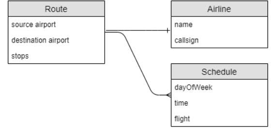
Figure 4.1 An example of a conceptual data model diagram. Source of image: https://www.couchbase.com/blog/conceptual-physical-logical-data-models/
Notice that we are not considering the data types. We are not considering how the data would be stored. We are not thinking about relationships. (Ignore the extra lines at the “Airline” box and at the “Schedule” box. We will address this topic elsewhere.) At this point, you could be thinking about a pile of papers on your desk or about a spreadsheet or about a database. At this point, you could be brainstorming on a whiteboard!

Figure 4.2 A large whiteboard. Source of image: https://www.magnatag.com/img/products/WW/WWcover1170-2.png
Do spend a good amount of time in this model. Once the stakeholders have agreed that everything has been identified, then you can advance to the next model.
Consider a database that has data on a school and on students. We will be focusing on entities and in time the relationships. In the relational DBMS approach, the term “Entity-Relationship Diagrams” (ERDs) is used.
We are interested in identifying the entities and the relationships. In an educational institution, we are looking at students, courses, instructors, and departments. For the relationships, we are looking at the following:
- Students enroll in courses.
- Instructors teach courses.
- Departments management courses.
Figure 4.3 illustrates the entities and the relationships.
|
Students |
|
Courses |
|
Instructors |
|
Departments |
|
|
Students take courses. |
|
Instructors teach courses. |
|
Departments manage courses. |
|
Figure 4.3 Entities and relationships.
We could add some details. For the school, we would need to track the name and a description. For the student, we would need to track the name and the date of birth. Figure 4.4 shows the two entities. (Ignore the extra lines at the “School” box and at the “Student” box. We will address this topic elsewhere.) However, the temptation is to jump to the logical model too early.
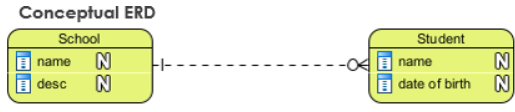
Figure 4.4 The Conceptual Model Source of image: https://guides.visual-paradigm.com/navigating-the-three-levels-of-database-design-conceptual-logical-and-physical/
The Logical Data Model — The “How of The Details” Model
We are adding more details to the conceptual model. You would look at the business rules and at the constraints. Look at the section entitled “Enforcement of Integrity Constraints” in Chapter 3.
You would define the data types, the data sizes, the lengths, and other details. We are not ready to select a DBMS. So use the generic term of “string” instead of “varchar” or “nvarchar.”
|
A Logical Model for a Future Relational Database |
A Logical Model for a Future Document Database |
|
|
|
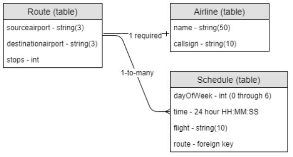
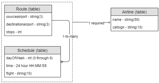
Figure 4.5 Two examples of a logical model. Source of image: https://www.couchbase.com/blog/conceptual-physical-logical-data-models/
It is a bit of the cart-before-the-horse situation. In the pure database work, you should not be thinking about the actual DBMS. But in order to draw the logical model, you need to have some foreknowledge into the nature of the future DBMS.
In the right-hand side of Figure 4.5, the Schedule table has a fairly small and finite footprint. So it makes sense to embed it into the same box or collection. This is bounding the Schedule table to the Route table.
In the left-hand side of Figure 4.5, the arrangement is slightly different.
For the educational institution example, we will use Figure 4.6 to illustrate the additional of the details.
|
Students |
|
Courses |
|
Instructors |
|
Departments |
|
StudentID |
|
CourseID |
|
InstructorID |
|
DepartmentID |
|
FirstName |
|
CourseName |
|
FirstName |
|
DepartmentName |
|
LastName |
|
Credits |
|
LastName |
|
|
|
DateOfBirth |
|
|
|
|
|
|
|
|
Students take courses. |
|
Instructors teach courses. |
|
Departments manage courses. |
|
Figure 4.6 Adding details to the entities.
Once done, we need to think about the data types. We need an identification number (ID) as a number, the name fields as a string, and the date of birth as a date. Figure 4.7 will illustrate this addition.
|
Students |
|
Courses |
|
Instructors |
|
Departments |
|
StudentID A number |
|
CourseID A number |
|
InstructorID A number |
|
DepartmentID A number |
|
FirstName A string |
|
CourseName A string |
|
FirstName A string |
|
DepartmentName A string |
|
LastName A string |
|
Credits A number |
|
LastName A string |
|
|
|
DateOfBirth A date |
|
|
|
|
|
|
|
|
Students take courses. |
|
Instructors teach courses. |
|
Departments manage courses. |
|
Figure 4.7 Adding details to the entities.
Here, we have the cart-before-the-horse situation. We know that the DBMS will be a relational DBMS. With this foreknowledge, we can state that the IDs will be integers (a whole number). We can state that the name fields will be varchar(255). We can state that the date of birth field will be a date data type. Figure 4.8 will illustrate this addition.
|
Students |
|
Courses |
|
Instructors |
|
Departments |
|
StudentID integer |
|
CourseID integer |
|
InstructorID integer |
|
DepartmentID integer |
|
FirstName varchar(255) |
|
CourseName varchar(255) |
|
FirstName varchar(255) |
|
DepartmentName varchar(255) |
|
LastName varchar(255) |
|
Credits Integer |
|
LastName varchar(255) |
|
|
|
DateOfBirth date |
|
|
|
|
|
|
|
|
Students take courses. |
|
Instructors teach courses. |
|
Departments manage courses. |
|
Figure 4.8 Revising the data types.
Also with this foreknowledge, we can start to think about relationships. This could result in the need to add more fields to a table. Imagine that all students must be assigned to a department. Figure 4.9 will illustrate this addition.
|
Students |
|
Courses |
|
Instructors |
|
Departments |
|
StudentID integer |
|
CourseID integer |
|
InstructorID integer |
|
DepartmentID integer |
|
FirstName varchar(255) |
|
CourseName varchar(255) |
|
FirstName varchar(255) |
|
DepartmentName varchar(255) |
|
LastName varchar(255) |
|
Credits Integer |
|
LastName varchar(255) |
|
|
|
DateOfBirth date |
|
|
|
|
|
|
|
DepartmentID |
|
|
|
|
|
|
|
|
Students take courses. |
|
Instructors teach courses. |
|
Departments manage courses. |
|
Figure 4.9 Adding a connecting field to the Student table.
The StudentID, the CourseID, the InstructorID, and the DepartmentID are known as primary keys. A primary key is unique and cannot be null, because it takes us to one row and only one row. The DepartmentID in the Student table is a foreign key, because it points back to the Department table.
Figure 4.10 is from database effort where the user wishes to track schools and students. Figure 4.10 illustrates the use of “SchoolID” in the second field in the Student table.
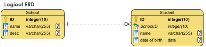
Figure 4.10 The Logical Model Source of image: https://guides.visual-paradigm.com/navigating-the-three-levels-of-database-design-conceptual-logical-and-physical/
Also, we need to look at constraints and at business rules. Students may be limited to taking no more than five courses in a semester. An instructor may be limited to teaching no more than four courses.
Are we done? No. Does your model cover the following?
- How to document an instructor teaching more than one session of a course?
- How to document the room assignment for a course?
- How to document the days and time for a course?
- How to document grades assigned to a student?
As you think through the issues, you may need to add more fields and to add more tables. There may be a need to add special tables that connect two tables.
The Physical Data Model — The “How of The Implementation” Model
Once we have enough details worked out on the logical data model, then it is time to actually implement it into a real DBMS. Which implementation makes sense?
If your modeling process reveals that your data model is likely to change frequently to adapt to new requirements, you might consider going with a document database. This might be a “NoSQL document database.
Other DBMS schemes have been covered in earlier chapters. You may review those for insights for choosing one of those.
If you decided on a relational model, then there are many options such as:
- Microsoft SQL Server Management Studio
- Oracle
- PostgreSQL
- MySQL
- Amazon Relational Database Service
- Azure SQL Database.
The physical data model may include:
- The selected DBMS.
- How and where the data would be stored.
- Details on how the data would be replicated.
The work of creating the database may be done by the database administrator or by the database developer.
A Few Words
This chapter introduced one approach for creating a database. The second edition used a different approach. It had the following:
- External model
- Conceptual model
- Internal model
- Physical model
The point of the approach is to capture the details. It does not matter whether one uses the three-model approached presented in this chapter or the four-model approach that was used in the second edition.
The rest of this textbook will go deeper into the relational DBMS design. Do not skip those chapters.
Key Terms
data type: This is how data is defined. It could be an integer, a string, a date, or something else. There are differences from DBMS to DBMS.
data models: Tools for going from a concept to a fully working database management system.
entities: The objects or the nouns that make up a database.
Entity-Relationship Diagram (ERD): This is used in relational DBMS work for modeling data.
framework: This is a more structured approach for solving a problem. The framework may have a set of guidelines or rules for completing a task.
integer: A whole number.
model: This is a simplified representation of a system or of a process. It is a tool for breaking the complex into smaller and more manageable parts.
foreign key: This is a primary key appearing in another table. (This was covered in Chapter 3.)
null: This is the absence of a user-defined value. This is not the same thing as zero. (This was covered in Chapter 3.)
primary key: This is a unique value for locating a row of data in a database table. (This was covered in Chapter 3.)
Exercises
- Why do we use models when working on a database?
- What is a data model?
- What is a high-level conceptual data model?
- You are creating a conceptual data model for an animal hospital. What are three possible entities?
- For question 4, what are some possible fields associated with the three entities?
- What are the possible relationships between the three entities?
- Using your answers to previous questions, create a logical model. (CS2013 IM/RD 1 and IS2020 A3.2.1.2)
- Describe the relationship between a logical model and a physical model. (IT2017 ITE-IMA-03b)
- Which model does the database administrator work with?
- As noted earlier in this chapter, models help to uncover errors. Do you see an error in Figure 4.11?
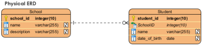
Figure 4.11 The Physical Model Source of image: https://guides.visual-paradigm.com/navigating-the-three-levels-of-database-design-conceptual-logical-and-physical/
A Running Project
A running project was introduced in Chapter 2. Review what you have collected. Have you overlooked anything?
If you are doing this as a service project or as an internship, continue to chat with the organization. If possible, chat with others besides the main contact person.
In Chapter 3, you were told to use a word processor to create tables with columns for the entity pieces. With the insights from this chapter, add the data types to each entity piece.
Attribution
This chapter of Database Design is a derivative copy of Database System Concepts by Nguyen Kim Anh licensed under Creative Commons Attribution License 3.0 license
Information from second edition Chapter 4 was not used. Question 1 and 2 were used and appear as questions 2 and 3.
The following material was written by Adrienne Watt for the second edition:
- Introduction
- Key Terms
- Exercises
The whole chapter was completely revised by Fred Strickland for the third edition.
References
Matthew Groves. “Data Modeling Explained: Conceptual, Physical, Logical,” Couchbase, October 7, 2022. https://www.couchbase.com/blog/conceptual-physical-logical-data-models/
Shawn Manaher. “Model vs Framework: When And How Can You Use Each One? The Content Authority, n.d. https://thecontentauthority.com/blog/model-vs-framework