5 Chapter 5 The Relational Data Model and the Entity Relationship Diagram (ERD)
Fred Strickland
Original Chapter 7 Author: Adrienne Watt
Original Chapter 8 Author: Adrienne Watt
Rewrite: Fred Strickland
Learning Outcomes
|
Computing Sub Discipline |
Document Code, Reference Code, and Page Number |
Text |
|
Computer Science |
CS2013 IM/Relational Databases (RD) (Pages 115-116) |
1. Prepare a relational schema from a conceptual model developed using the entity- relationship model. [Usage] Repeated learning outcome. 9. Determine whether a set of attributes form a superkey and/or candidate key for a relation with given functional dependencies. [Assessment] |
|
CS2023 DM Modeling: Data Modeling (Pages 116-117) |
CS Core 2. Relational data model. KA Core 3. Conceptual models (e.g., entity-relationship, UML diagrams) ILO CS Core 1. Describe the components of the relational data model. ILO CS Core 3. Describe the components of the E-R (or some other non-relational) data model. |
|
|
CS2023 DM Relational: Relational Databases (Pages 117-118) |
CS Core 2. Relational database design. KA Core 3. Mapping conceptual schema to a relational schema ILO CS Core 1. Describe the defining characteristics behind the relational data model. ILO CS Core 2. Comment on the difference between a foreign key and a superkey. |
|
|
Information Systems |
IS2020 A3.2 Data / Information Competency Realm (Page 101) A3.2.1 Competency Area – Data / Information Management (Page 101) |
2. Design relational databases (Page 103) Repeated learning outcome |
|
Information Technology |
IT2017 ITE-IMA-03 Data modeling (Page 92) |
a. Design Entity Relationship diagrams based on appropriate organizational rules for a given scenario. |
Introduction to Chapter 5
In Chapter 4, we began to look at the three-model approach for creating a database. This was at a high level with some relational database management system (DBMS) examples. We did not cover everything in the logical data model. We will continue in this chapter.
The second edition Chapter 7 was a short chapter that explored at a high level the relational data model. The second edition Chapter 8 explored the entity relationship data model. For the third edition, these two chapters have been combined.
Background on the Relational Data Model
Figure 5.1 Image of Edgar Frank “Ted” Codd. Source of image: https://studymate.tutorialathome.in/postimg/e-f-codd.jpg
The relational data model was introduced by Edgar Frank “Ted” Codd in 1970. Currently, it is the most widely used data model.
The relational model has provided the basis for:
- Research on the theory of data/relationship/constraint
- Numerous database design methodologies
- The standard database access language called structured query language (SQL)
- Almost all modern commercial database management systems
The relational data model describes the world as “a collection of inter-related relations (or tables).”
Fundamental Concepts in the Relational Data Model
Relation
Formally, a relation is a subset of the Cartesian product of a list of domains characterized by a name. Informally, this is a relation between two entities. This is also known as a table or file. And within a table, each row represents a group of related data values. A row, or record, is also known as a tuple. A column is a field and is also referred to as an attribute. A domain is the set of allowable values for a column.
You can also think of it this way: An attribute is used to define the record and a record contains a set of attributes. The permitted or legal values are listed in the domain.
The above can be formally expressed as follows:
- Given n domains are denoted by D1, D2, … Dn
- And r is a relation defined on these domains.
- Then r ⊆ D1×D2×…×Dn
Formal notations are used as common language when users come from different backgrounds. You can think about languages that are used for diplomacy or for business such as Latin, French, and English. Now to examine each term in greater detail.
Table
A database is composed of multiple tables and each table holds the data. Figure 7.2 shows a database that contains three tables.
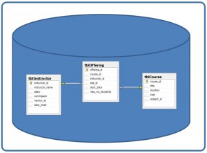
Figure 5.2. Database with three tables. Source of image: Second Edition Figure 7.2
Column
The principal storage units are called columns or field or attributes. These house the basic components of data into which your content can be broken down.
When deciding which fields to create, you need to think generically about your information. For example, drawing out the common components of the data that you will store in the database and avoiding the specifics that distinguish one item from another. Look at the example of an ID card in Figure 7.3 to see the relationship between a field and its data.
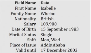
Figure 5.3. Example of an ID card by A. Watt. Source of image: Second Edition Figure 7.3
Domain
A domain is the original sets of atomic values used to model data. By atomic value, we mean that each value in the domain is indivisible as far as the relational model is concerned. For example:
- The domain of Marital Status has a set of possibilities: Married, Single, Divorced.
- The domain of Workdays has the set of all possible days: {Mon, Tue, Wed…}.
- The domain of Salary is the set of all floating-point numbers greater than 0 and less than 200,000.
- The domain of First Name is the set of character strings that represents names of people.
In summary, a domain is a set of acceptable values that a column is allowed to contain. This is based on various properties and the data type for the column. We will discuss data types in another chapter.
Records
Just as the content of a document or item needs to be broken down into its constituent bits of data for storage in the fields, the link between these also needs to be available so that the individual record can be reconstituted into the original form. Working with records allow us to do this. Records contain fields that are related, such as a customer or an employee. As noted earlier, a tuple is another term used for record.
Records and fields form the basis of all databases. A simple table gives us the clearest picture of how records and fields work together in a database.
|
RecordID |
PubDate |
Author |
Title |
|
1 |
26/07/1968 |
B. Pitt |
Rights and Wrongs Online |
|
2 |
3/5/2000 |
A. Jolie |
Networking for Change |
|
3 |
27/02/1971 |
J. Carter |
The Myth of Cyber Crimes |
|
4 |
15/09/1983 |
I. Wheaton |
Connecting the Disconnected |
Figure 5.4. Example of a simple table by A. Watt. (Revised by F. Strickland)
Figure 5.4 shows a table with fields for holding data. This one has:
- The attribute name is unique in a table. These are in the row with light blue.
- Below the attribute name are cells containing the values.
- A row contains cells that are related in some fashion. This is sometimes called a tuple.
- The RecordID field contains whole numbers. The data type is an integer.
- The PubDate field contains dates that are expressed in day/month/year format. The data type is date.
- The Author field contains strings that are displayed in first initial and surname format. The data type is text.
- The Title field contains strings that are free text. The data type is text.
Degree
The degree is the number of attributes in a table. In Figure 5.4, the degree is 4.
Properties of a Table
A database table has some properties:
- A table has a name that is distinct from all other tables in the database.
- It is possible to have two databases and each one has a table with the same name.
- There are no duplicated rows.
- According to database design best practices, a database table should not contain duplicated rows. To ensure that duplicated rows do not happen, primary keys are used.
- Duplicate rows could happen in
- A staging table.
- A table that does not have a primary key.
- Entries in columns are atomic or cannot be broken down further.
- The table does not contain repeating groups or multivalued attributes.
- Entries in a column are from the same domain based on their data type such as:
- number (numeric, integer, float, smallint,…)
- character (string)
- date
- logical (true or false)
- Operations combining different data types are disallowed.
- This is possible if a cast function is used. This converts a value of one data type to another data type.
- For example, you wish to convert the string value of “2” to an integer so you an add it to an integer. CAST (“2” AS int) + 2 would be 4 instead of “22.”
- This is possible if a cast function is used. This converts a value of one data type to another data type.
- Each attribute has a distinct name or unique name in a database table.
- It is possible to have two data tables and each one has a column with the same name.
- The sequence or ordering of the columns is insignificant.
- The sequence or ordering of the rows is insignificant.
Background on the Entity-Relationship Model
In 1976, Peter Chen introduced the entity–relationship (ER1) model. In his paper, he wrote about the model being a tool for designing databases. His approach would support data integrity, information retrieval, and data manipulation. The model draws upon the network model, the relational model, and the entity set model. In the introduction to his paper, he noted the strengths and the weaknesses of these three models. In his own words, he wrote:
- The network model provides a more natural view of data by separating entities and relationships (to a certain extent), but its capability to achieve data independence has been challenged.
- The relational model is based on relational theory and can achieve a high degree of data independence, but it may lose some important semantic information about the real world.
- The entity set model, which is based on set theory, also achieves a high degree of data independence, but its viewing of values such as “3” or “red” may not be natural to some people.
Chen’s model has a more natural view of the real world—a world of entities and relationships. His model has a high degree of data independence. It is based on set theory and relation theory. Chen introduced a special diagramming technique for working on database designs that he called the entity-relationship diagram (ERD). (See the references for two links to the complete Peter Chen paper.)
Entities, Relationships, and Attributes
Chen focused on three parts:
- Entities as something that “exists in our minds.” An entity could be a tangible type or could be a non-tangible type. These can be classified into different entity sets.
- Relationships as an “associations among entities.”
- A marriage is a relationship between two entities in the entity set Person.
- Attributes as an “information about an entity or a relationship….”
- “3”, “red”, “Peter”, and “Johnson” are values.
- “Values are classified into different value sets, such as FEET, COLOR, FIRST-NAME, and LAST-NAME.”
Illustrating the ER Model and the ERD
For the rest of this chapter, we will use a sample database (Company) to illustrate the ER model and the ERD. We will be using the following symbols:
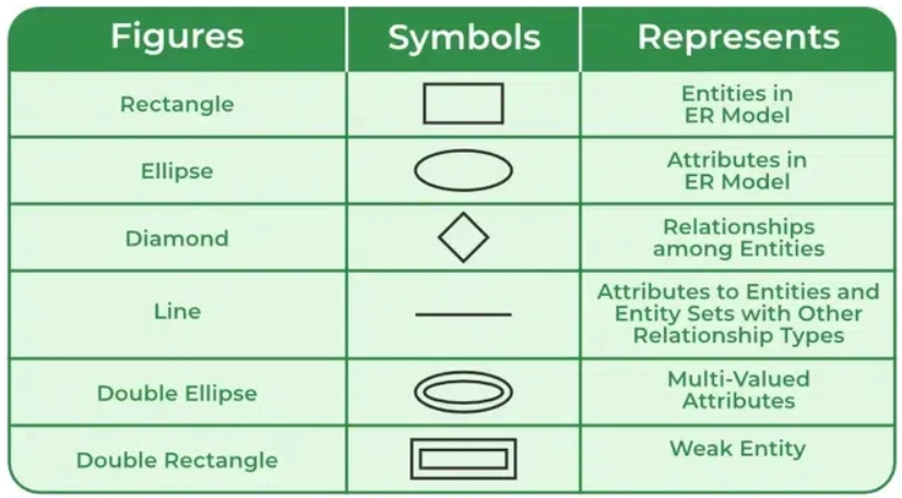
Figure 5.5 Symbols used in an ER Diagram. Source of image: https://www.geeksforgeeks.org/introduction-of-er-model/
The Company database contains data about employees, departments, and projects. The ERD symbol for these is a rectangle:
|
Employee |
|
Department |
|
Project |
Figure 5.6 ERD for the three Company entities.
We need to note the following important points about the Company database:
- There are several departments in the company. Each department has a unique identification, a name, an office location, and a particular employee who manages the department.
- A department controls a number of projects. Each project has a unique name, a unique number, and a budget.
- Each employee has a name, an identification number (ID), an address, a salary, and a birthdate.
- An employee is assigned to one department.
- An employee reports to one direct supervisor.
- An employee could be a part of several projects.
- We need to record the start date of the employee in each project.
- An employee may have dependents.
- Each dependent has a name, a birthdate, and a relationship to the employee.
Entity Existence Dependency
Entities can be classified based on strength. An entity is considered strong if it can exist apart from all related entities. An entity is considered weak if its existence depends upon a corresponding entity in another entity set. Chen used the phrase “existence dependency” to describe this relationship. In Chen’s own words: “… [the] existence of an entity in the entity set D[ependent] depends on the corresponding entity in the entity set E[mployee]. That is, if an employee leaves the company, his dependents may no longer be of interest.” Figure 5.7 illustrates a strong entity and a weak entity.
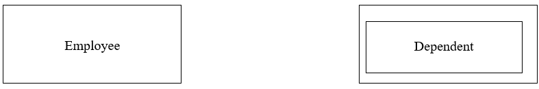
Figure 5.7 Strong entity on the left-hand side and a weak entity on the right-hand side.
Relationship Type and Degree of a Relationship Set
A relationship type represents the association between entity types. For example, in Figure 5.8 “Enrolled in” is a relationship type that exists between entity type “Student” and entity type “Course.” In the ERD, the relationship type is represented by a diamond. Lines are used to connect the entity types and the relationship types. Figure 5.8 shows two strong entities. Figure 5.9 shows a strong entity with a weak entity.

Figure 5.8 Relation type with two strong entities. Source of image: https://www.geeksforgeeks.org/introduction-of-er-model/
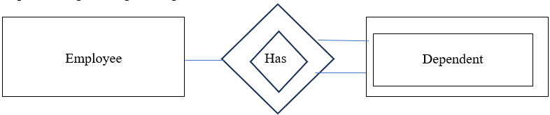
Figure 5.9 Strong entity and a weak entity.
Geeks for Geeks explained relationship set as “a set of relationships of the same type” The website has an illustration, but it does not clearly explain the definition. The concept of a degree of a relationship set does clear up the confusion. This is the number of different entity sets participating in a relationship set.
Degree of a Relationship Set: Unary
When there is only one entity set participating in a relation, the relationship is called a unary relationship. For example, one person is married to only one person.
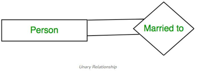
Figure 5.10 An example of a person being married to a person. Source of image: https://www.geeksforgeeks.org/introduction-of-er-model/
A variation of Figure 5.10 would not be used in the Company database. The exception would be if the company had a business rule that it hires only husbands and wives as a team.
There is a recursive unary relationship. This is when there is a relationship between members of the same entity set. For example, an employee is a supervisor of another employee. Figure 5.11 illustrates this relationship. In the actual Employee table, it might be necessary to add a column for the supervisor’s ID.
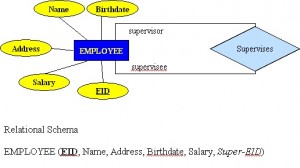
Figure 5.11 Example of a unary relationship. Source of image: Second Edition Figure 8.9
Degree of a Relationship Set: Binary
When there are two entities set participating in a relationship, the relationship is called a binary relationship. Figure 5.12 illustrates a binary relationship with the Employee table and the Spouse table. Note how this is different from Figure 5.10, which has both individuals appearing in the same table.
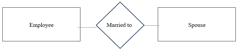
Figure 5.12 An employee is associated with a spouse.
The Geeks for Geeks website used an example from education. See Figure 5.13 for a Student being enrolled in a Course.

Figure 5.13 An example of a binary relationship. Source of image: https://www.geeksforgeeks.org/introduction-of-er-model/
Degree of a Relationship Set: Ternary
This is when more than two entity sets participate in a relation.
Attribute Symbol
For an entity type, we define the properties. These are represented in ovals.
Key Attribute
An attribute that uniquely identifies each entity is called a key attribute. This is represented with the word underlined in an oval.
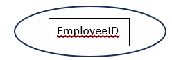
Figure 5.14 An example of a key attribute.
Composite Attributes
Composite attributes are those that consist of a hierarchy of attributes. Using the Employee table from the Company database, the Address may consist of a Number, a Street, and a Suburb. This is represented with two or more ovals coming out of another oval. See Figure 5.15. This could be written as
→ Address = {59 + ‘Meek Street’ + ‘Kingsford’}
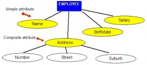
Figure 5.15. An example of composite attributes. Source of image: Second Edition Figure 8.3
Multivalued Attributes
Multivalued attributes are attributes that have a set of values for each entity. An example of a multivalued attribute from the Company database is illustrated in Figure 7.16. An employee could have more than one academic degree such as BSc, MIT, and PhD. This is represented as a double oval.
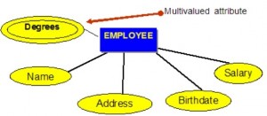
Figure 5.16. Example of a multivalued attribute. Source of image: Second Edition Figure 8.4
Derived Attributes
Derived attributes are attributes that are derived from other attributes. This is represented as a dotted oval in Figure 5.17.
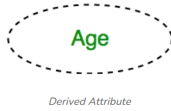
Figure 5.17 Example of a derived attribute. Source of image: https://www.geeksforgeeks.org/introduction-of-er-model/
The Need for Keys
In the paragraphs on “key attribute,” we defined this as something that uniquely identifies an entity. We did not cover the various types of keys nor did we explain how the primary key is selected. We will address those questions in this section.
Types of Keys
There are several types of keys that can be used to locate a record. Geeks for Geeks illustrate all of the possible keys (Figure 5.18):

Figure 5.18 Diagram of all possible keys in a DBMS. Source of image: https://www.geeksforgeeks.org/candidate-key-in-dbms/
These are described below.
Super Key
A super key is a set of one or more attributes (columns), which can uniquely identify a row in a table.
Using the Employee table from the Company database example, we might have the following attributes:
- EmployeeID
- FirstName
- LastName
- SSN4
- Address
- Phone
- BirthDate
- Salary
- DepartmentID
The possible super keys are:
- EmployeeID
- FirstName (Assuming that this is unique.)
- LastName (Assuming that this is unique.)
- SSN
- Address (Assuming that this is unique.)
- Phone (Assuming that this is unique.)
- BirthDate (Assuming that this is unique.)
- Salary (Assuming that this is unique.)
- DepartmentID (Assuming that this is unique.)
- EmployeeID, FirstName
- EmployeeID, LastName
- EmployeeID, SSN
- EmployeeID, Address
- EmployeeID, Phone
- EmployeeID, BirthDate
- EmployeeID, Salary
- EmployeeID, DepartmentID
- FirstName, LastName (Assuming that the combination is unique.)
- FirstName, SSN
- FirstName, Address (Assuming that the combination is unique.)
- FirstName, Phone (Assuming that the combination is unique.)
- FirstName, BirthDate (Assuming that the combination is unique.)
- FirstName, Salary (Assuming that the combination is unique.)
- FirstName, DepartmentID (Assuming that the combination is unique.)
- LastName, SSN
- LastName, Address (Assuming that the combination is unique.)
- LastName, Phone (Assuming that the combination is unique.)
- LastName, BirthDate (Assuming that the combination is unique.)
- LastName, Salary (Assuming that the combination is unique.)
- LastName, DepartmentID (Assuming that the combination is unique.)
- SSN, Address
- SSN, Phone
- SSN, BirthDate
- SSN, Salary
- SSN, DepartmentID
- Address, Phone (Assuming that the combination is unique.)
- Address, BirthDate (Assuming that the combination is unique.)
- Address, Salary (Assuming that the combination is unique.)
- Address, DepartmentID (Assuming that the combination is unique.)
- Phone, BirthDate (Assuming that the combination is unique.)
- Phone, Salary (Assuming that the combination is unique.)
- Phone, DepartmentID (Assuming that the combination is unique.)
- BirthDate, Salary (Assuming that the combination is unique.)
- BirthDate, DepartmentID (Assuming that the combination is unique.)
- Salary, DepartmentID (Assuming that the combination is unique.)
Candidate Key
A candidate key is a simple or composite key that is unique and minimal. Another way to view a candidate key is that the minimal super key has no redundant attributes.
The possible candidate keys are:
- EmployeeID
- FirstName (Assuming that this is unique.)
- LastName (Assuming that this is unique.)
- SSN
- Address (Assuming that this is unique.)
- Phone (Assuming that this is unique.)
- BirthDate (Assuming that this is unique.)
- Salary (Assuming that this is unique.)
Primary Key
A primary key is selected from the set of candidate keys. This done by the database administrator or by the database designer. More than likely one of the following would be selected:
- EmployeeID
- SSN
Alternate Key (or Secondary Key)
After the primary key has been selected, then the other candidate keys are the alternate keys. If EmployeeID was selected as the primary key, then SSN would be the alternate key. Or if SSN was selected as the primary key, then the EmployeeID would be the alternate key:
- EmployeeID
- SSN
Composite Key (or Compound Key)
A composite key (or compound key) uses more than one attribute to locate a record.
One way to think about a composite key is when you attempt to access an account and you do not have the account number. Other pieces are used to locate your account.
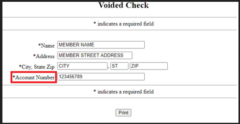
Figure 5.19 Example of how to locate an account when the number is not known. Source of image: https://s3.amazonaws.com/cdn.freshdesk.com/data/helpdesk/attachments/production/47043169576/original/Htjf1hvCQ9afJXvY2vQ54XHtVlLPsuQTGw.png?1603288395
The possible composite keys are:
- EmployeeID, FirstName
- EmployeeID, LastName
- EmployeeID, SSN
- EmployeeID, Address
- EmployeeID, Phone
- EmployeeID, BirthDate
- EmployeeID, Salary
- EmployeeID, DepartmentID
- FirstName, LastName (Assuming that the combination is unique.)
- FirstName, SSN
- FirstName, Address (Assuming that the combination is unique.)
- FirstName, Phone (Assuming that the combination is unique.)
- FirstName, BirthDate (Assuming that the combination is unique.)
- FirstName, Salary (Assuming that the combination is unique.)
- FirstName, DepartmentID (Assuming that the combination is unique.)
- LastName, SSN
- LastName, Address (Assuming that the combination is unique.)
- LastName, Phone (Assuming that the combination is unique.)
- LastName, BirthDate (Assuming that the combination is unique.)
- LastName, Salary (Assuming that the combination is unique.)
- LastName, DepartmentID (Assuming that the combination is unique.)
- SSN, Address
- SSN, Phone
- SSN, BirthDate
- SSN, Salary
- SSN, DepartmentID
- Address, Phone (Assuming that the combination is unique.)
- Address, BirthDate (Assuming that the combination is unique.)
- Address, Salary (Assuming that the combination is unique.)
- Address, DepartmentID (Assuming that the combination is unique.)
- Phone, BirthDate (Assuming that the combination is unique.)
- Phone, Salary (Assuming that the combination is unique.)
- Phone, DepartmentID (Assuming that the combination is unique.)
- BirthDate, Salary (Assuming that the combination is unique.)
- BirthDate, DepartmentID (Assuming that the combination is unique.)
- Salary, DepartmentID (Assuming that the combination is unique.)
Foreign Key
A foreign key is used to link one table to another table. Or this is an attribute in a table that references the primary key in another table.
This could be null. Both foreign and primary keys must be of the same data type.
In the Company database example, DepartmentID is the foreign key in the Employee table:
Employee(EID, First Name, Last Name, SIN, Address, Phone, BirthDate, Salary, DepartmentID)
Key Terms
alternate key (or secondary key): These are the unselected candidate keys.
atomic values: This means that the value cannot be broken down into small pieces.
attributes: This is information about an entity or about a relationship.
cast function: This is a way of converting a value to another data type.
candidate key: This is a way of converting a value to another data type.
column: This is an attribute.
composite attribute: This is an attribute that is composed of two or more pieces.
composite key: This uses more than one attribute to locate a record.
degree: This is the number of columns in a table.
degree of a relationship set: This is the number of different entity sets participating in a relationship set.
derived attribute: This is derived from other attributes.
domain: This is the set of allowable values for a column.
entity or entities: In the words of Peter Chen, these are things that “exists in our minds.” An entity is an object in the real world with an independent existence that can be differentiated from other objects.
Entity-Relationship Diagram: Peter Chen developed this tool in support of the entity-relationship model.
Entity-Relationship Model: Peter Chen developed this model in 1976. It draws upon the network model, the relational model, and entity set model. It is a more natural view of the real world. It is based on sets theory and relational theory.
entity set: This is a collection of entities. In the words of Peter Chen, an entity “has the properties common to the other entities in the entity set….”
existence dependency: An entity that dependents upon the existence of another entity. This is a weak relationship. If the linked entity is removed, then these dependent entities would go away.
field: See column above.
file: See relation below.
Foreign key: This is used to link from one table to another table.
key attribute: This is an attribute that uniquely identifies an entity.
multivalued attribute: This is an attribute that could contain more than one entity.
non-tangible type: This is an entity that is not physical and cannot be touched.
primary key: This is selected from the set of candidate keys. Recall from Chapter 3 that this was defined as a unique value for locating a row of data in a database table.
relation: Formally, this is a subset of the Cartesian product of a list of domains characterized by a name. Informally, this is a relation between two entities.
relationship type: This represents the associations between entity types.
relationships: In the words of Peter Chen, this an “association among entities.”
record: See row below.
recursive relationship: See unary relationship.
row: This represents a group of related data.
staging table: This is a table that is receiving data from different sources.
super key: This is a set of one or more attributes (columns), which can uniquely identify a row in a table.
table: See relation above.
tangible type: This is an entity that is physical or could be touched.
ternary: This is when more than two entity sets participate in a relation.
tuple: See row above.
unary relationship: This is one in which a relationship exists between occurrences of the same entity set.
Exercises
Use Table 5.1 to answer the first four questions.
Use Table 5.2 to answer questions 7 through 10.
Use both tables to answer question 11.
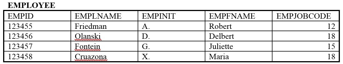
Table 5.1 Table for exercise questions, by A. Watt
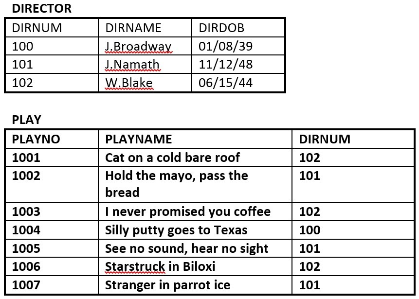
Table 5.2 Director and Play tables by A. Watt
- Using correct terminology, identify and describe all the components in Table 5.1.
- What is the possible domain for field EmpJobCode?
- How many records are shown?
- How many attributes are shown?
- List the properties of a database table.
- What three concepts or parts of the ERD?
- Identify the super keys in Table 5.2.
- Identify the candidate keys in Table 5.2. (CS2013 IM/RD 9)
- Identify the primary keys in Table 5.2.
- Identify the foreign key in Table 5.2.
- Use Table 5.1 and Table 5.2 and create an ERD. You may need to make some assumptions. (CS2013 IM/RD 1, IS2020 A3.2.1.2, and IT2017 ITE-IMA-03a)
- Define the following:
- Relation
- Column
- Domain
- Records
- Degree
- Entities
- The ERD rectangle
- The ERD oval or ellipse
- The ERD double oval.
- The ERD double rectangle
- Weak entities
- Strong entities
- Unary degree
- Binary degree
- Ternary degree
- Key attribute
- Composite attributes
- Multivalued attributes
- Derived attributes
- Super key
- Candidate key
- Primary key
- Alternate key
- Composite key
- Foreign key
A Running Project
A running project was introduced in Chapter 2. You were encouraged to collect insights about the needs. In Chapter 3, you were told to use a word processor to create tables with columns for the entity pieces. In Chapter 4, you were told to identified the data types.
In this chapter, you are to begin to create the ERD. Refer to Figure 5.5 for the symbols.
Create a list of the possible keys. Identify the primary keys.
Again, review what you have collected. Have you overlooked anything?
Attribution
This chapter of Database Design is a derivative copy of Database System Concepts by Nguyen Kim Anh licensed under Creative Commons Attribution License 3.0 license
The following material was written by Adrienne Watt for the second edition:
- Introduction
- Key Terms
- Exercises
This chapter drew from chapter 7 and from chapter 8. The information was completely revised by Fred Strickland for the third edition.
References
Peter Chen. “The Entity-Relationship Model—Toward a Unified View of Data,” ACM Transactions on Database Systems, Volume 1, Number 1, March 1976. The abstract and the first draft page can be found at https://dl.acm.org/doi/10.1145/1095277.1095279 An unofficial copy of the paper is available at https://dspace.mit.edu/bitstream/handle/1721.1/47432/entityrelationshx00chen.pdf and at https://www.comp.nus.edu.sg/~lingtw/papers/tods76.chen.pdf
This was a groundbreaking paper, but it had some errors. For example, Figure 2 had the title of “Attributes defined on the entity set PERSON,” but in the drawing the entity set was named “EMPLOYEE.”
Sergey Gigoyan. “Find and Remove Duplicate Rows from a SQL Server Table,” MSSQLTips, July 20, 2021. https://www.mssqltips.com/sqlservertip/4486/find-and-remove-duplicate-rows-from-a-sql-server-table/
Chaitanya Singh. “Alternate key in DBMS,” BeginnersBook, December 11, 2018. https://beginnersbook.com/2015/04/alternate-key-in-dbms/
Chaitanya Singh. “Composite key in DBMS,” BeginnersBook, December 11, 2018. https://beginnersbook.com/2015/04/composite-key-in-dbms/
Chaitanya Singh. “Foreign key in DBMS,” BeginnersBook, December 11, 2018. https://beginnersbook.com/2015/04/foreign-key-in-dbms/
Chaitanya Singh. “Super key in DBMS,” BeginnersBook, December 11, 2018. https://beginnersbook.com/2015/04/super-key-in-dbms/
“Introduction of ER Model,” Geeks for Geeks, May 23, 2024. https://www.geeksforgeeks.org/introduction-of-er-model/
“SQL Server CAST() Function,” W3 Schools, n.d. https://www.w3schools.com/sql/func_sqlserver_cast.asp