6 Chapter 6 Integrity Rules, Constraints, and Cardinality
Fred Strickland
Original Chapter 9 Author: Adrienne Watt and Nelson Eng
Rewrite: Fred Strickland
Learning Outcomes
|
Computing Sub Discipline |
Document Code, Reference Code, and Page Number |
Text |
|
Computer Science |
CS2013 IM/Relational Databases (RD) (Pages 115-116) |
2. Explain and demonstrate the concepts of entity integrity constraint and referential integrity constraint (including definition of the concept of a foreign key). [Usage] Repeated learning outcome. |
|
CS2023 DM-Modeling: Data Modeling (Pages 116-117) |
ILO CS Core 2. Model 1:1, 1:n, and n:m relationships using the relational data model. |
|
|
CS2023 DM relational: Relational Databases (Pages 117-118) |
CS Core 1. Entity and referential integrity: Candidate key, superkey ILO CS Core 3. Enumerate the different types of integrity constraints. ILO KA Core 4. Compose a relational schema from a conceptual schema which contains 1:1, 1:n, and n:m relationships. |
|
|
Data Science |
DS2021 Data Integrity (DPSIA/DI) (Page 89) DPSIA/DI Logical Integrity –T1 (Page 89)
|
Students need to have knowledge of
Repeated learning outcome. Added “user-defined integrity.” |
|
Information Technology |
IT2017 ITE-IMA-02 Data information concepts (Page 92) |
c. Illustrate data quality, accuracy, and timeliness, and explain how their absence will impact organizations. |
|
IT2017 ITE-IMA-03 Data modeling (Page 92) |
a. Design Entity Relationship diagrams based on appropriate organizational rules for a given scenario. Repeated learning outcome |
|
|
IT2017 ITE- IMA-05 Data organization architecture (Page 92) |
d. Evaluate data integrity and provide examples of entity and referential integrity. Repeated learning outcome |
|
Introduction to Chapter 6
Bad or duplicate data could be entered into a spreadsheet. There are no mechanisms for preventing this from happening. The same thing could happen in a database. However, there are mechanisms for preventing this from happening. We use integrity rules, constraints, and cardinality to ensure the high quality of the data.
Integrity Rules
Chapter 3 introduced the concept of enforcing integrity constraints. Four types were listed. In this chapter, we will add a fifth constraint and we will go deeper into this area.
When data is added to a database or is updated or is deleted, accidental damage could happen. Integrity rules or integrity constraints or relational integrity constraints are conditions that must be present for a valid relation and thus prevent accidental damage. There are at least four types of integrity rules:
|
Geeks for Geeks List |
Educative List |
Java T Point List |
|
Domain Integrity |
Domain Constraints |
Domain Constraint |
|
Entity Integrity Business Key Integrity |
Entity Integrity |
Entity Integrity Constraint |
|
Referential Integrity |
Referential Integrity Constraint |
Referential Integrity Constraint |
|
|
Key Constraints |
Key Constraints |
|
User-defined Integrity |
|
|
Figure 6.1 Three integrity rule lists. (See the reference list for the URLs.)
Domain Integrity or Domain Constraints
In Chapter 5, the term “domain” was explained as a set of atomic values used to model data. The following examples were provided:
- The domain of Marital Status has a set of possibilities: Married, Single, Divorced.
- The domain of Workdays has the set of all possible days: {Mon, Tue, Wed…}.
- The domain of Salary is the set of all floating-point numbers greater than 0 and less than 200,000.
- The domain of First Name is the set of character strings that represent names of people.
The phrase “domain integrity” or “domain constraint” goes one step further by restricting the entities in a column to a certain set of values and data types.
|
LastName |
FirstName |
Department |
Phone |
Room |
|
Abbasi |
Reza |
CBA |
604-777-6615 |
N4313 |
|
Bashir |
Mehwish |
CBA |
604-527-5080 |
N4335E |
|
Caldwell |
Rhyon |
CBA |
604-777-6577 |
N4313 |
|
Eng |
Nelson |
CBA |
Vancouver number |
N4335J |
Figure 6.2 Sample Douglas College directory for faculty in the Computing Studies and Information Systems Department as a database table. Source: Publicly available data on https://sundryapps.douglascollege.ca:8443/phonebook/index.php
The phone number for Nelson Eng violates the domain, because all phone numbers consist of digits and hyphens. Letters are not permitted.
Entity Integrity or Entity Integrity Constraints
In Chapter 5, the concept of a key was explored. The intent was to uniquely identify a row in a table. We looked at super keys, at candidate keys, at primary keys, at alternate keys, at composite keys, and at foreign keys. In the example Company database, we saw that EmployeeID and SSN could be used as a primary key. The database administrator or the database designer would decide which one would be used. (Review the Chapter 5 section entitled “Types of Keys” for a fuller treatment of this topic.)
Entity integrity or sometimes written as “entity integrity constraints” states that each row in a table must have some unique data. This would be the primary key. The value for a primary key cannot appear twice in the same table. The value for a primary key cannot be null.
|
ID |
FirstName |
LastName |
City |
TwoLetterPostalCode |
|
1 |
James |
Smith |
Vancouver |
BC |
|
2 |
John |
Johnson |
Grand Falls |
NB |
|
3 |
Robert |
Williams |
Toronto |
ON |
|
4 |
Michael |
Brown |
Caribou |
ME |
|
NULL |
William |
Jones |
Presque Isle |
ME |
Figure 6.3 Example of a database table from Chapter 3 with a change in the last row. (The title row has been changed based on the style guide described elsewhere in this chapter.)
The last row in Figure 6.3 contains “NULL.” If the student ID is the primary key for this table, then the presence of “NULL” violates the entity integrity rule.
Referential Integrity (or Referential Integrity Constraint)
Referential integrity or referential integrity constraint requires that if a table contains a column for foreign keys, then the linked table must have a matching value in the primary key column. That is, the value in the foreign key column must also be present in the primary key column of the linked table. The foreign key column could contain “NULL” values.
In “Illustrating the ER Model and the ERD” section in Chapter 5, we listed three tables with the following important points:
- There are several departments in the company. Each department has a unique identification, a name, an office location, and a particular employee who manages the department.
- A department controls several projects. Each project has a unique name, a unique number, and a budget.
- Each employee has a name, an identification number, an address, a salary, and a birthdate.
- An employee is assigned to one department.
- An employee reports to one direct supervisor.
- An employee could be a part of several projects.
- We need to record the start date of the employee in each project.
- An employee may have dependents.
- Each dependent has a name, a birthdate, and a relationship to the employee.
In Chapter 5, we looked at the table that contained employee data. This table had the following fields:
- EmployeeID
- FirstName
- LastName
- SSN1
- Address
- Phone
- BirthDate
- Salary
- DepartmentID
Based on the above mentioned points, the table containing department data had at least the following fields:
- DepartmentID
- Name
- Location
- Manager
Here is a possible display:
|
EmployeeID |
FirstName |
LastName |
SSN |
Address |
Phone |
BirthDate |
Salary |
DepartmentID |
|
1 |
James |
Smith |
1 |
Vancouver |
123 |
01-01-1960 |
GS10-1 |
1 |
|
2 |
John |
Johnson |
2 |
Grand Falls |
234 |
01-01-1970 |
GS9-1 |
1 |
|
3 |
Robert |
Williams |
3 |
Toronto |
345 |
01-01-1980 |
GS9-1 |
2 |
|
4 |
Michael |
Brown |
4 |
Caribou |
456 |
01-01-1990 |
GS8-1 |
2 |
|
5 |
William |
Jones |
5 |
Presque Isle |
567 |
01-01-2000 |
GS7-1 |
2 |
Figure 6.4 Example of the Employees2 table. (The entries are fictional.)
|
DepartmentID |
Name |
Location |
Manager |
|
1 |
Human Resources |
One Plaza |
1 |
|
2 |
Shipping |
Main Warehouse |
2 |
|
3 |
Receiving |
Loading Dock One |
3 |
Figure 6.5 Example of the Departments table
These two tables satisfy the referential integrity requirements. Every DepartmentID in the Employees table can be found in the Departments table. A new employee could be added to the Employee table with a NULL value for the DepartmentID. This would mean that the employee has not been assigned to a department. If the Company database has only three departments, then a DepartmentID of “4” would violate the referential integrity requirements, because it would be pointing to a non-existent department.
Key Constraints
Key constraints state that a primary key must be unique.
|
ID |
FirstName |
LastName |
City |
TwoLetterPostalCode |
|
1 |
James |
Smith |
Vancouver |
BC |
|
2 |
John |
Johnson |
Grand Falls |
NB |
|
3 |
Robert |
Williams |
Toronto |
ON |
|
4 |
Michael |
Brown |
Caribou |
ME |
|
1 |
William |
Jones |
Presque Isle |
ME |
Figure 6.6 Example of a database table from Chapter 3 with a change in the first row and in the last row.
The last row in Figure 6.1 contains “1.” If the student ID is the primary key for this table, then the second occurrence of “1” violates the key constraints rule.
User-Defined Integrity (or Business Rules)
User-defined integrity items are also known as “business rules.” These could vary from organization to organization.
For example, at Douglas College if a student takes 9 credit hours, then the student is classified as a full-time student. At the University of Maine at Presque Isle if a student takes 12 credit hours, then the student is classified as a full-time student.
Here are more examples.
- A class can have a maximum of 30 students.
- A teacher can teach a maximum of four classes per semester.
- An employee cannot take part in more than five projects.
- The salary of an employee cannot exceed the salary of the employee’s manager.
Style Guides
Each organization will have an approach for naming tables and columns. This is known as a naming convention. Experts disagree about what is the best approach. We will explore this area and then define what will be used for the rest of the book. (We have hinted at some of these style elements earlier in this chapter.)
Use Meaningful Names
We have used “Employee” and “Department” as examples table names. We did not use “Person.” Nor did we use “Organization.” These table names are too generic. With a table name of “Person,” we would not know if the table holds employee data, vendor data, or customer data. Similar issue with the generic table name of “Organization.”
Expressing the Names
This is where the experts have the greatest disagreement. In computing programming, there are four naming conventions:
- Camel case
- Kebab case
- Pascal case
- Snake case
Camel case runs the words together. The first word has a lower-case letter and the other words start with an upper case letter.
- employeeID
- departmentID
- firstName
Java programmers use camel casing for creating variable names.
Kebab case separates each word with the dash or hyphen character.
- Employee-ID or employee-ID
- Department-ID or department-ID
- First-Name or first-name
Writers of URLs use this approach. This approach is not commonly used in computer programming nor in databases. The benefit is avoiding the need to use the shift key with any top row characters.
Pascal case runs the words together. All words start with an upper-case letter.
- EmployeeID
- DepartmentID
- FirstName
Many programming languages use the Pascal case for naming classes. This approach is used in many databases. Gustavo du Mortier recommends this approach, although he sometimes incorrectly refers to this approach as camel casing.
Snake case separates each word with an underscore character. This is similar to Kebab case.
- Employee_ID or employee_ID
- Department_ID or department_ID
- First_Name or first_name
Python programmers use this approach. This is frequently seen in databases for table and column names. This is the approach that Nicole Yaeger recommends, but without any upper-case letters.
There is a variation that uses all upper-case letters. This is known as “screaming snake case.” Java uses this for declaring constants (a data item that does not change its value during program execution).
The drawbacks of using the snake case:
- Typing the underscore character requires holding down the shift key and reaching up to the top row of the keyboard.
- The object names become longer.
- The underscore character does not add any value or meaning.
- On some computer displays, the underscore character can be hard to see.
As a fifth approach, Nicole Yaeger uses all lower-case letters for table names and for column names.
Singular Names or Plural Names
There are two schools of thought. One school of thought uses singular names, because an entity is a single thing instead of a set of things. The following are examples of this approach for tables:
- Employee
- Department
- Order
The other school of thought uses plural names, because the table or view holds more than one entity. The following are examples of this approach for table names:
- Employees
- Departments
- Orders
Gustavo du Mortier favors the plural approach. He pointed out, “If you are making a wooden box for your kid’s toys, would you label it ‘Toy’ or ‘Toys’?”
For the column names, Gustavo du Mortier prefers singular names.
Avoid Generic or Meaningless Names
Variable names in a programming language should be self-describing. This should be true for a database. Avoid names that are similar to the following:
- GeneralData
- Config
- DataTable
- ImportedRecords
- Flag
- Scrap
- Table1
Nicole Yaeger pointed out that reserved words should not be used as table names nor as column names.
Avoid Using Foreign Languages for Naming Objects
The United Nations has six official languages:
- Arabic
- Chinese
- English
- French
- Russian
- Spanish
The German language may have been the language of science, but it does not enjoy the same acceptance as English currently does. As Tsedal Neeley noted in an article on global business, English is spoken by 1.75 billion people and many multinational companies require their employees to use English. For these reasons, English must be used in database development.
Prefixes
Gustavo du Mortier went into great detail about prefixes. His viewpoint is that prefixes are useful for grouping objects related to a particular application, but not for a database.
Nicole Yaeger likes this approach for database objects. So she would use “tbl_customers” or “table_customers” for a customer table. For most situations, Gustavo du Mortier views prefixes as unnecessary and prone to create more confusion. More meaningful names would solve this problem. For example, instead of having “TblProducts” and VueProducts,” use “Products” and “ImportedProducts.”
Gustavo du Mortier views the adding of the table name to a field name as unnecessary. So our running Company database fields goes against this viewpoint and needs to be corrected:
- employee_ID would become ID.
- Student_ID would become ID.
- department_ID would become ID.
This approach avoids the need to figure out if one should be using “student_ID” or “StudentID” or another form.
So how does one reference employee IDs and department IDs? The answer is to use the dotted scheme approach. This is done frequently in modern programming languages for accessing an object’s field or method. So that approach would be done as follows for use within an SQL environment:
- employeeID would become Employees.ID with a period just before “ID.”
- departmentID would become Departments.ID.
Another approach for handling long strings is to use aliases. This topic will be covered in the chapter on using SQL commands.
Unclear Abbreviations
There are many approaches used for shortening long strings. One approach is to remove vowels. This was the approach used in hard copy telephone books. Another approach is to cut off the letters beyond a certain point. Another approach is to use common abbreviations with the long name. You might see entries like the following:
- EmployeeID might be rendered as EmplID.
- DepartmentID might be rendered as DprtmntID.
- ItemNumber might be rendered as ItemNo, ItemNbr, or ItemNr.
Many times, the database designer has to create a data dictionary in order to spell out the abbreviations. It is better to stick with the long forms. Using the guidance from the “Prefix” section, the entries would be shorter. And a data dictionary might not be necessary.
Avoid Using Non-Standard Syntax
The SQL syntax will be covered in another chapter. The SQL standards cover what is needed by most users. A database software company may add extra commands in order to make their product distinctive or add a unique capability.
Gustavo du Mortier provided an example from Microsoft. Microsoft call their version of SQL “Transact-SQL.” Spaces and periods are not used in table names, in field names, and in other places. Transact-SQL supports using brackets for enclosing names with unsupported characters.
Here is an example with the table name of “Pending Orders.Details:”
- SELECT * FROM [Pending Orders.Details]
This is confusing, because the dotted approach is normally used to select a field in a table. The asterisk (*) is a wild card character and it is used to select all columns from the named table.
This has the drawback of being locked to one vendor. Changing to a different vendor’s database software would be hard to do.
Be Careful of Using Low-Code or No-Code Development Tools
These tools attempt to prevent direct access to the database objects. This may be done for copyright reasons. Or may be done to keep the user locked to the vendor. These tools will intentionally obfuscate the names of the database objects.
The Third Edition Style Guide
With so many approaches for creating a database, Gustavo du Mortier suggests placing a “Naming Convention” box on the ERD diagram. Figure 6.7 shows what could be used for documenting the style on a database diagram.
|
Naming Convention:
|
Figure 6.7 Example of a database naming convention box. Adapted from https://vertabelo.com/blog/database-schema-naming-conventions/
This is the style guide that this book will follow for this chapter and for the other chapters.
Cardinality
Cardinality is a mathematical term. It deals with the number of elements in a set. This term has a slightly different definition when applied to databases.
Cardinality describes the relationship between two database tables by expressing the minimum and maximum number of entity occurrences associated with one occurrence of a related entity.
In Chapter 9 of the second edition, this topic was approached from the viewpoint of connectivity with cardinality. Figure 6.8 shows Figure 9.2 from the second edition.
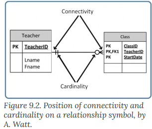
Figure 6.8 Reproduction of Figure 9.2 from the second edition.
Most authorities have a different approach. The approach is cardinality with optionality. Figure 6.9 shows an example of this approach:
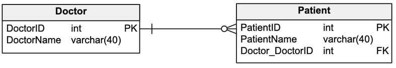
Figure 6.9 Example of cardinality with optionality. Source of image: https://vertabelo.com/blog/cardinality-in-data-modeling/
There are three relationships:
- One-to-one
- Sometimes written as “1 to 1.”
- One-to-many
- Sometimes written as “1 to M”
- Many-to-many
- Sometimes written as “M to N.”
Some websites will count many-to-one as a fourth relationship.
Optionality states whether or not an entity must be joined to another entity.
In Figure 6.9, one doctor (the vertical bar |) could have zero to many patients (the empty circle to the left of the trio of lines coming from the circle).
Before we continue, we need to have a “Crash Course on ERD Schemes.”
Crash Course on ERD Schemes
The following notation styles are arranged in chronological order.
The Charles Bachman Notation Style (circa 1963)
The Bachman Notation Style uses rectangles, ovals, and diamonds. This encodes the relationships with black and white dots.
|
Bachman Symbols |
Example Relationships |
|
|
|
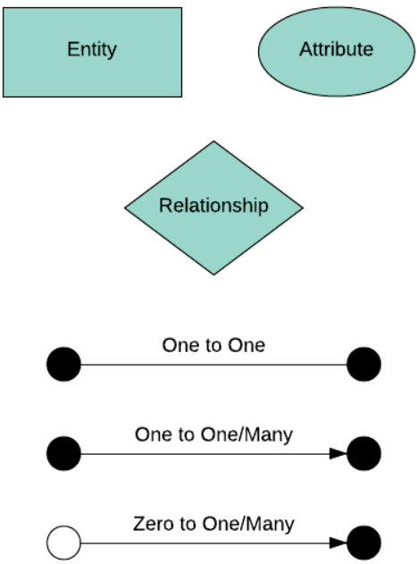
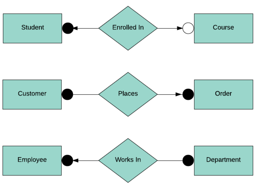
Figure 6.10 Examples of the Bachman symbols and relationships. Source of images: https://www.databasestar.com/entity-relationship-diagram/#Symbols_and_notations
The Crow’s Foot Notation Style (1970s)
The Crow’s Foot Notation Style uses rectangles with two sections. The top part has the title and the bottom part contains the attribute fields. Mandatory relationships are shown as a solid line and optional relationships are shown as a dotted line.
|
Crow’s Foot Symbols |
Example Relationships |
|
|
|
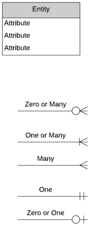
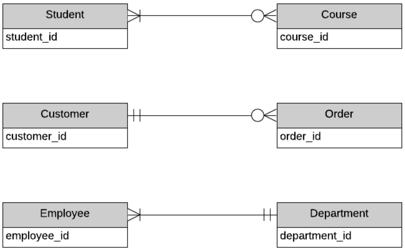
Figure 6.11 Examples of the Crow’s Foot symbols and relationships. Source of images: https://www.databasestar.com/entity-relationship-diagram/#Symbols_and_notations
The Peter Chen Notation Style (1976)
The Chen Notation Style uses rectangles, ovals, and diamonds. Mandatory relationships are shown as a solid line and optional relationships are shown as a dotted line.
|
Chen Symbols |
Example Relationships |
|
|
|
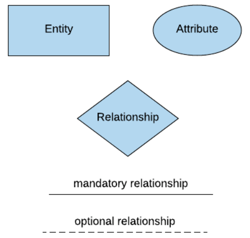
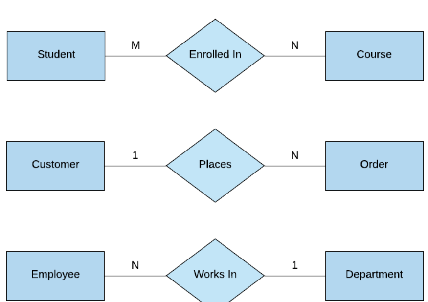
Figure 6.12 Examples of the Chen symbols and relationships. Source of images: https://www.databasestar.com/entity-relationship-diagram/#Symbols_and_notations
The Chen Notation Style is not well-suited for complex data models. The graphic elements require much space and may not provide any useful value. Figure 6.13 illustrates how complex a Human Resource database could be. Figure 6.13 also illustrates how much space is consumed by this diagram.
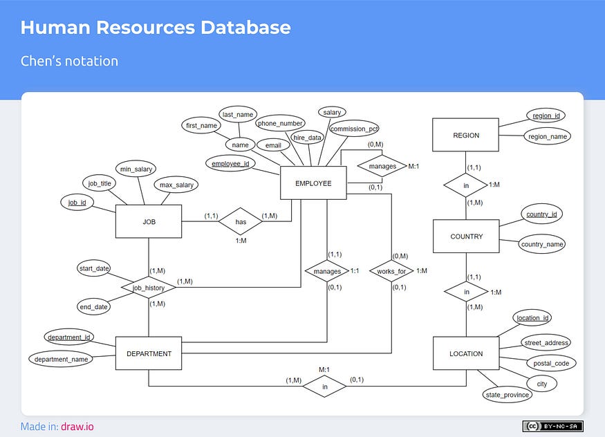
Figure 6.13 Human Resource Database in Chen’s notation. Source of image: https://medium.com/@ericgcc/dont-get-wrong-explained-guide-to-choosing-a-database-design-notation-for-erd-in-a-while-7747925a7531
Eric Gcc provided the following pros and cons for using the Chen’s approach:
- Pros
- Provides lots of information: Most books that cover relational database design tend to use this notation.
- Uses basic figures: One can draw an ERD with practically any program that has rectangles, diamonds, ovals, and lines (Eric Gcc’s comment: “ehem … [Microsoft W]ord”).
- Cons
- Notation takes up much space: All the figures the notation uses cause very large and difficult to read diagrams.
- No database modeler includes this notation: Therefore, you cannot autogenerate a logical or physical diagram and much less SQL or reverse engineering.
- Not used in the industry: Because of the previous point, you will hardly find the use of these diagrams in a company.
Eric Gcc recommends this model for academic uses only.
The IDEF1X Notation Style (1981)
Integration DEFinition For Information Modeling Notation Style used rectangles. This encoded the relationships with black dots with cardinality notes below the line.
|
IDEF1X Symbols |
Example Relationships |
|
|
|
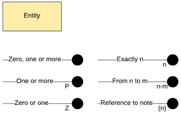
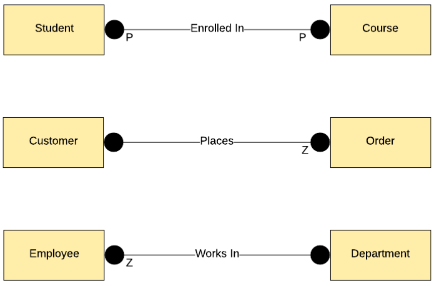
Figure 6.14 Examples of the IDEF1X symbols and relationships. Source of images: https://www.databasestar.com/entity-relationship-diagram/#Symbols_and_notations
Eric Gcc does not consider this be a true database notation, because it is a hybrid of other notation schemes. It mixes conceptual model concepts with the construction of a relational database.
- Pros
- It is used by many branches of the United States government.
- Cons
- It has four different ways to show a mandatory one-to-one relationship.
- It has four different ways to show an optional one-to-one relationship.
- Symbols are more suited for the physical design than for the concept design.
The Information Engineering (IE) Notation Style (Early 1980s)
IE Notation Style used rectangles. Attributes are displayed in a compartment below the entity type name. There are different versions and no single standard exists. Despite this issue, IE is supported by many data modeling tools and is one of me most popular notations for database design. Vertabelo has this as its default ER diagram notation. Vertabelo also calls this “Crow’s Foot Notation.”
|
Vertabelo IE Symbols |
Example Relationships |
|
|
|
|
Smartdraw IE Symbols |
Smartdraw Example Relationships |
|
|
|
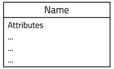


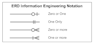
Figure 6.15 Examples of the IE symbols and relationships. Source of images: https://medium.com/@ericgcc/dont-get-wrong-explained-guide-to-choosing-a-database-design-notation-for-erd-in-a-while-7747925a7531 and https://www.smartdraw.com/other-software-diagrams/examples/ie-notation-logical-data-model/
Compare Figure 6.16 with Figure 6.13. Notice how much clearer is the IE diagram than the Chen diagram.
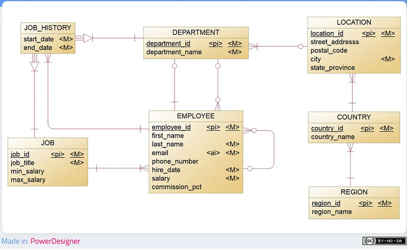
Figure 6.16. Human Resource Database in IE’s notation. Source of images: https://medium.com/@ericgcc/dont-get-wrong-explained-guide-to-choosing-a-database-design-notation-for-erd-in-a-while-7747925a7531
Eric Gcc noted the following differences from the Chen’s Notation Style:
- Attributes are listed inside the entity rectangles. Chen uses a series of connecting ovals to the entity box.
- Attributes can be specified as mandatory, as an identifier, as unique, or as optional.
- Relationships are binary.
- An intersection entity is used to model relations with n-ary and to model relationships with attributes.
- Mutually exclusive relationships do not exist.
- There is no symbol for representing a weak entity.
- In PowerDesigner, a triangle is used to point to a strong entity. See Figure 6.17.
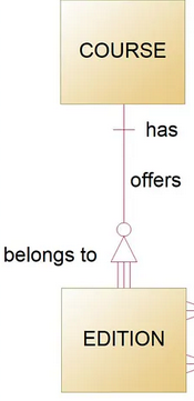
Figure 6.17. An example of how the PowerDesigner uses a triangle with IE notation for showing a weak entity. Source of image: https://medium.com/@ericgcc/dont-get-wrong-explained-guide-to-choosing-a-database-design-notation-for-erd-in-a-while-7747925a7531
Eric Gcc provided the following pros and cons for using the IE’s approach:
- Pros
- Widely used: Most of the diagrams you review will use this notation.
- Easy to read: Crow’s feet notation is well known. The graphic elements are optimal, and if you stick to the convention of designing from left to right and top to bottom, the diagrams are understandable.
- Cons
- There is no standard: Several versions exist and can be confusing because of the different representations.
Eric Gcc recommends this model for all situations:
Use always, as IE is by far the most popular notation. Practically all modelers support the notation (with slight differences). There are many examples and documentation. It is likely that if you find an ERD made by someone else, he or she had used IE.
The Richard Barker Notation Style (1990)
The Barker Notation Style used rectangles with rounded edges. Mandatory relationships are shown as a solid line and optional relationships are shown as a dotted line. A trio of lines is used to show many relationships.
|
Barker Symbols |
Example Relationships |
|
|
Note: The Database Star website incorrectly drew these entities with 90-degree corners. |


Figure 6.18 Examples of the Barker symbols and relationships. Source of images: https://www.databasestar.com/entity-relationship-diagram/#Symbols_and_notations
Compare Figure 6.19 with Figure 6.13. Notice how much clearer is the Barker diagram than the Chen diagram.
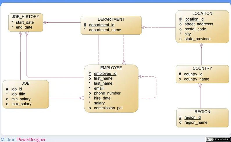
Figure 6.19 Human Resource Database in Barker’s notation. Source of image: https://medium.com/@ericgcc/dont-get-wrong-explained-guide-to-choosing-a-database-design-notation-for-erd-in-a-while-7747925a7531
Eric Gcc noted the following differences from the Chen’s Notation Style:
- Attributes are listed inside the entity rounded corners rectangles. Chen uses a series of connecting ovals to the entity box.
- All attributes are atomic. There is no concept of a composite attribute.
- There is no symbol for representing a weak entity.
Eric Gcc provided the following pros and cons for using the Barker’s approach:
- Pros
- Expressive notation: It includes restrictions that other notations do not, and it is still widely used.
- Fewer symbols: Use relatively few symbols. There are no weak entities, and a simplified crow’s feet notation is used.
- Cons
- Entity hierarchies: The subtype tends to become unhelpful and messy with hierarchies of various levels of depth.
- The subtype system is not the best.
Eric Gcc recommends this model for working with Oracle related technologies.
The Arrow Notation Style (Unknown Year)
The Arrow Notation Style is not well-known. It uses rectangles with arrows.
|
Arrow Symbols |
Example Relationships |
|
|
The presentation of attributes could be like the IDEF1X notation or like the UML approach.
|
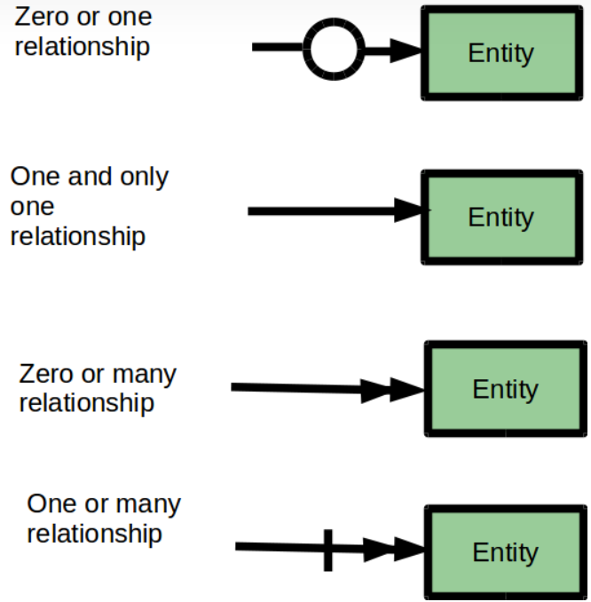
Figure 6.20 Examples of the Barker symbols and relationships. Source of images: https://vertabelo.com/blog/arrow-notation/
The UML Notation Style (UML was released in 1997.)
The Unified Modeling Language (UML) was provided as a common design language tool that could be used to develop and build computer applications. It is like the blueprint for a building. UML is not a methodology. It uses the following:
- Use case diagram
- Class diagram
- Sequence diagram
- Statechart diagram
- Activity diagram
- Component diagram
- Deployment diagram.
UML is not a tool for the Entity-Relationship Model. At some point, UML was pressed into service to be a separate higher-level database design model. UML database design has the following diagrams:
- Structural Diagrams
- Behavioral Diagrams
UML models classes and relationships.
|
UML Class Symbol |
Example Relationships |
|
Legend: +: public attributes #: Protected attributes -: Private attributes |
|
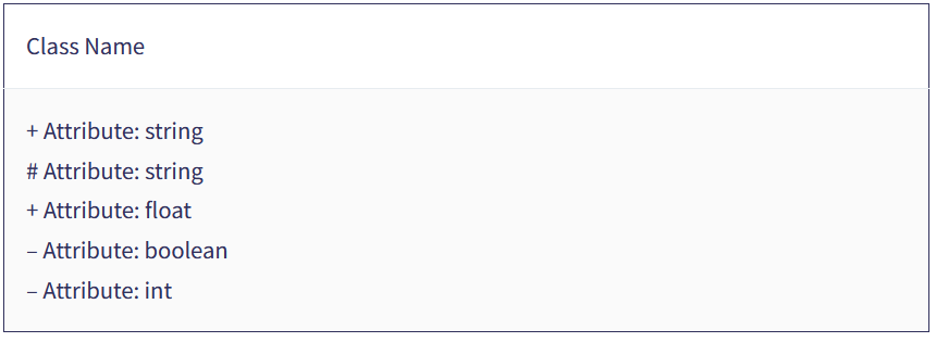
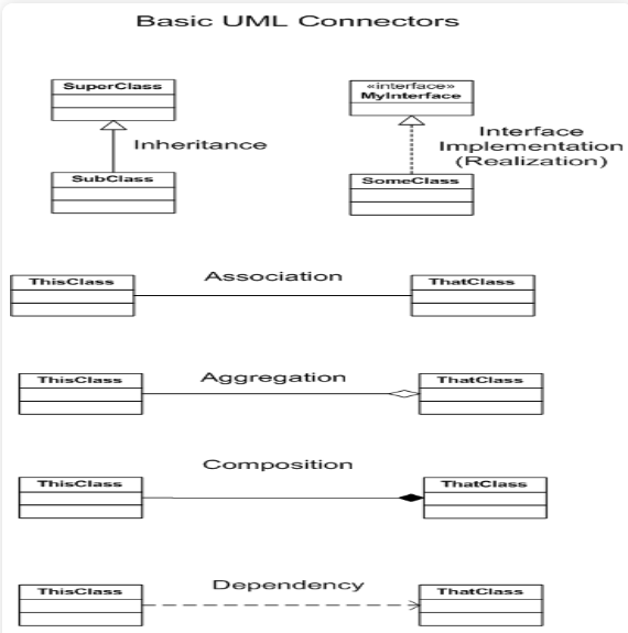
Figure 6.21 Examples of the UML symbols and relationships. Source of images: https://hevodata.com/learn/uml-database-modeling/
Compare Figure 6.22 with Figure 6.13. Notice how cardinality and attributes are documented.

Figure 6.22 Human Resource Database in UML notation. Source of image: https://medium.com/@ericgcc/dont-get-wrong-explained-guide-to-choosing-a-database-design-notation-for-erd-in-a-while-7747925a7531
Eric Gcc noted the following differences from the Chen’s Notation Style:
- Attributes are listed inside the entity rectangles. Chen uses a series of connecting ovals to the entity box.
- UML uses inheritance.
- There is no symbol for representing a weak entity.
- A composition is an association that implies that a child entity cannot exist without its parent entity. It is represented using a line with a filled diamond next to the parent (strong) entity.
Eric Gcc provided the following pros and cons for using the UML’s approach:
- Pros
- Widely used: UML exists, and thanks to its advantages and despite its disadvantages, it is quite common in the industry.
- It’s a standard: Unlike most ERD notations, UML is an International Standards Organization (ISO) recognized standard since 2005, so you won’t find all the variants of the other notations.
- The suite of notations: The UML class diagram has advantages over other notations as it can pick up much more semantics from the requirements.
- Modelers: There is a wide range of open source and licensing software options designed for this notation. Some database modelers also support UML.
- Cons
- Environment: Although it’s used to design databases, UML has not been as successful as other ERD modeling approaches.
- The suite of notations: Includes much more than is required for an entity-relationship model, but with patience, you can “clean up” and use an appropriate subset of the notation.
- Forward and reverse engineering: Since UML is not popular in database design, there are few tools to convert a class diagram to SQL (or vice versa) with no great results.
Eric Gcc recommends this model when the entire system will be following an object-oriented approach.
Microsoft’s Database Diagram Tool in SQL Server Management Studio (Unknown Year)
Database diagram support was present for many years through version 17.9. It was removed in version 18.0. It was added back in version 18.1.
It models tables and relationships. It has the table title in bold font and the columns are indented. Relationships are shown with the infinity symbol and a house key.
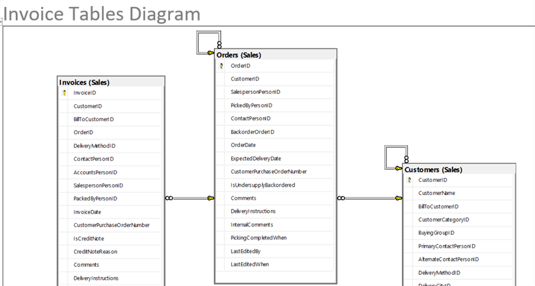
Figure 6.23 Invoice tables diagram in Microsoft Database Diagram notation. Source of image: https://www.mssqltips.com/sqlservertip/6269/sql-server-database-diagram-tool-in-management-studio/
Adam Adamowicz provided the following pros and cons for using:
- Pros
- You can expand the details for the column attributes.
- You can hide all non-key columns.
- You can display just the table names.
- You can design a custom view of the tables.
- You select which tables to display on the diagram.
- You can add more tables to a diagram.
- You can add annotations to the diagram.
- You can save the diagram with the database. It is saved in the dbo.sysdiagrams table.
- You can store several diagrams.
- You can export the diagram as clipart.
- Schema changes are automatically reflected on the diagram.
- Cons
- You can add labels to a relationship, but it is always the name of the foreign key constraint and thus not very useful.
- Limited formatting capabilities.
- Cannot add views to a diagram.
- Cannot show relationships that are defined in a foreign key constraint
- Requires access to the database.
My biggest complaint is that this tool cannot be used to plan a database. That is, the database must exist before this tool can be used.
The Third Edition Notional Style Guide: IE’s Notation with Crow’s Foot Notation Plus Pascal Case
The second edition used Chen’s Notation Style for documenting the attributes and used the Crow’s Foot Notation Style for documenting connectivity with cardinality. Snake casing was used for the actual words. This style was used for some of the examples in the first five chapters of this edition.
The third edition will use IE’s Notation Style as rendered by Smartdraw for the tables. Crow’s Foot Notations will be used for documenting the cardinality with optionality. The naming convention from Figure 6.7 will be used. This style guide was used for all examples in this chapter and will continue to be used for the rest of the book.
To provide linkage to the second edition, the Chen’s Notation Style will be presented below the IE’s Notation Style with Crow’s Foot Notations.
More on Cardinality
We will be using the Crow’s Foot Notations for documenting cardinality with optionality. There are slightly different from the Crow’s Foot Notation Style for documenting connectivity with cardinality.
Optional Relationships
In an optional relationship, the foreign key (FK) could be null or the parent table does not need to have a corresponding child table occurrence. The symbol, shown in Figure 6.24, illustrates this with a zero (an oval) and three prongs (indicating many) which is interpreted as zero OR many.

Figure 6.24 Zero or more. Reproduction of Figure 9.6 from the second edition.
Figure 6.25 shows that a person could be in the Customers table without an order. Or the person could have many orders active. This edition documents this from the cardinality with optionality viewpoint and is shown in the top half. The second edition documents this from the cardinality with connectivity viewpoint and is shown in the bottom half. For both viewpoints, the many side is optional.
|
Third edition |
|||||||||||||||
|
|||||||||||||||
|
Second Edition |
|||||||||||||||
|
|
|||||||||||||||


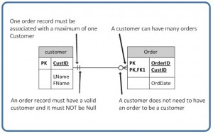
Figure 6.25 Example usage of a zero to many optional relationship symbol. The bottom image is a reproduction of Figure 9.7 from the second edition (A. Watt).
Figure 6.26 shows another type of optional relationship symbol with a zero and one, meaning zero OR one. The one side is optional.

Figure 6.26 Zero or one. Reproduction of Figure 9.8 from the second edition.
Figure 6.27 shows that a person could be in the Employees table without a spouse. Or the person could have one spouse. This edition documents this from the cardinality with optionality viewpoint and is shown in the top half. The second edition documents this from the cardinality with connectivity viewpoint and is shown in the bottom half. For both viewpoints, the one side is optional.
|
Third edition |
|||||||||||||||
|
|||||||||||||||
|
Second Edition |
|||||||||||||||
|
|
|||||||||||||||


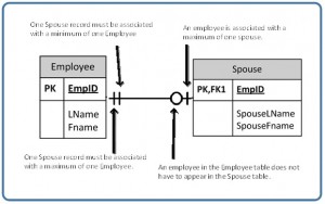
Figure 6.27 Example usage of a zero or one optional relationship symbol. The bottom image is a reproduction of Figure 9.9 from the second edition (A. Watt).
Mandatory Relationships
In a mandatory relationship, one entity occurrence requires a corresponding entity occurrence. The symbol for this relationship shows one and only one as shown in Figure 6.28.

Figure 6.28 One and only one. Reproduction of Figure 9.10 from the second edition.
Figure 6.29 shows that a person cannot be in the Employees table without a spouse. This edition documents this from the cardinality with optionality viewpoint and is shown in the top half. The second edition documents this from the cardinality with connectivity viewpoint and is shown in the bottom half. For both viewpoints, the one side is required.
|
Third edition |
|||||||||||||||
|
|||||||||||||||
|
Second Edition |
|||||||||||||||
|
|
|||||||||||||||


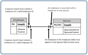
Figure 6.29 Example usage of the one and one only relationship symbol. The bottom image is a reproduction of Figure 9.11 from the second edition (A. Watt).
Next is Figure 6.30. The cardinality with optional views this as one or more. The second edition had two definitions for the cardinality with connectivity view:
- In the paragraph preceding Figure 9.12, this is “a one to many relationship … where the many side is mandatory.”
- In the paragraph preceding the example figure (Figure 9.13), this is “the one to many” relationship.

Figure 6.30 One or more. Reproduction of Figure 9.12 from the second edition.
Figure 6.31 shows that an order cannot exist without one or more products. There cannot be a place holder order. This edition documents this from the cardinality with optionality viewpoint and is shown in the top half. The second edition documents this from the cardinality with connectivity viewpoint and is shown in the bottom half. For both viewpoints, the one or more side is required.
|
Third edition |
|||||||||||||||
|
|||||||||||||||
|
Second Edition |
|||||||||||||||
|
|
|||||||||||||||


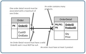
Figure 6.31 Example usage of one or more relationship symbol. The bottom image is a reproduction of Figure 9.13 from the second edition (A. Watt).
Notes on the Second Edition
The second edition addressed whether a relationship between tables involved one table that had a PK with an embedded FK. This was described an identifying relationship with a solid line (where the PK contains the FK) or as a non-identifying relationship with a broken line (where the PK does not contain the FK). Many of the second edition examples used a solid line when by this definition should have used a dotted line.
Since we are using the IE notation, this is not an issue. There is no symbol for representing a weak entity.
Key Terms
camel case: This runs the words together. The first word has a lower-case letter and the other words start with an upper case letter. This is the formal definition. However, there are authorities that use “camel case” when the intent is Pascal case.
cardinality: This describes the relationship between two data tables by expressing the minimum and maximum number of entity occurrences associated with one occurrence of a related entity.
cardinality with optionality: This describes the relationship between two data tables by expressing the minimum and maximum number of entity occurrences associated with one occurrence of a related entity. One entity could have 0, 1, or many connections in another table.
domain integrity (or domain constraints): These restrict the entities in a column to a certain set of values and data types.
integrity rules (or integrity constraints or relational integrity constraints): These are conditions that must be present for a valid relation.
Entity integrity (or entity integrity constrains): This means that each row in a table must have some unique data. This would be the primary key. The value for a primary key could not appear twice in the same table. The value for a primary key cannot be null.
kebab case: This separates each word with the dash or hyphen character
key constraints: The value for a primary key cannot be used again in the same table.
mandatory relationship: Where one entity occurrence requires a corresponding entity occurrence.
naming convention: An organization’s approach for naming tables and columns.
optionality: This states whether or not an entity must be joined to another entity.
Pascal case: This runs the words together. All words start with an upper-case letter.
referential integrity (or referential integrity constraint): This means that if a table contains a column for foreign keys, then the linked table must have a matching value in the primary key column. That is, the value in the foreign key column must also be present in the primary key column of the linked table.
snake case: This is a style where the words are separated by the underscore character.
user-defined integrity (or business rules): These are unique to an organization.
Exercises
- Explain the concept of domain constraints and provide two examples different from what you provided to Chapter 03 Question 7. Provide four examples where a database table violates this concept.
- Explain the concept of entity integrity constraints and provide two examples different from what you provided to Chapter 03 Question 8. Provide four examples where a database table violates this concept. (CS2013 IM/RD 2 and IT2017 ITE-IMA-05d)
- Explain the concept of referential integrity constraints. Be sure to address the concept of a foreign key in your answer. Provide two examples different from what you provided to Chapter 03 Question 9. Provide four examples where a database table violates this concept. (CS2013 IM/RD 2 and IT2017 ITE-IMA-05d)
- Explain the concept of key constraints and provide two examples. Provide four examples where a database table violates this concept.
- Explain the concept of user-defined integrity constraints and provide two examples. Provide four examples where a database table violates this concept. (DS2021 DPSIA/DI Logical Integrity—T1)
- Explain the benefits of following a style guide. What do you think of the third edition style guide? What is your preference for the following:
- Expressing names
- Singular Names or Plural Names
- Prefixes or not
- To abbreviate or not
- In the context of a database, explain cardinality.
- What are the three main cardinality relationships?
- Eric Gcc provided two pros and one con for using the IE. List these.
- In the following table, explain the cardinality symbols based on the third edition definitions:
|
Cardinality Symbol |
Your Answer |
|
|
|
|
|
|
|
|
|
|
|
|


This is for Questions 11 through 13:
The swim club database has been designed to hold information about students who are enrolled in swim classes. The following information is stored: students, enrollment, swim classes, pools where classes are held, instructors for the classes, and various levels of swim classes.
Cardinality assumptions:
- A pool may or may not ever have a class.
- The levels table must always be associated with at least one class.
- The staff table may not have ever taught a class.
- All students must be enrolled in at least one class.
- The class must have students enrolled in it.
- The class must have a valid pool.
- The class may not have an instructor assigned.
- The class must always be associated with an existing level.
11. Take the raw information and render as logic concept tables.
|
Raw Information |
Logic Concept Tables (This Edition Style) |
|
Pool |
|
|
Staff |
|
|
Classes |
|
|
Enrollment |
|
|
Students |
|
|
Levels |
|
12. Identify the keys.
13. Then determine what the cardinality with optionality relationships between the tables. State your assumptions.
A Running Project
A running project was introduced in Chapter 2. You were encouraged to collect insights about the needs. In Chapter 3, you were told to use a word processor to create tables with columns for the entity pieces. In Chapter 4, you were told to identify the data types. In Chapter 5, you were told to create ERD. Those should have been simple items.
You can revise your ERD to follow the third edition style guide or you may continue to follow the second edition style guide.
For your ERD, add PK and FK to your tables.
For cardinality, you can draw the symbols between the tables. Or you can describe the cardinality relationships between the tables.
Again, review what you have collected. Have you overlooked anything?
Attribution
This chapter of Database Design is a derivative copy of Database System Concepts by Nguyen Kim Anh licensed under Creative Commons Attribution License 3.0 license
The second edition chapter 9 did not contain an attribution section. Adrienne Watt and Nelson Eng were listed as joint authors.
This chapter drew from chapter 9. The information was completely revised by Fred Strickland for the third edition.
Image Attributions
The old Figures 9.3, 9.4, 9.6, 9.8, 9.10, 9.12, 9.14 and 9.15 by A. Watt.
References
Adam Adamawicz. “How to create ER diagram for existing SQL Server database with SSMS,” Dataedo, June 25, 2018. https://dataedo.com/kb/tools/ssms/create-database-diagram
Peter Chen. “The Entity-Relationship Model—Toward a Unified View of Data,” ACM Transactions on Database Systems, Volume 1, Number 1, March 1976. The abstract and the first draft page can be found at https://dl.acm.org/doi/10.1145/1095277.1095279 An unofficial copy of the paper is available at https://dspace.mit.edu/bitstream/handle/1721.1/47432/entityrelationshx00chen.pdf and at https://www.comp.nus.edu.sg/~lingtw/papers/tods76.chen.pdf
This was a groundbreaking paper, but it had some errors. For example, Figure 2 had the title of “Attributes defined on the entity set PERSON,” but in the drawing the entity set was named “EMPLOYEE.”
Pinal Dave. “Database Diagram – Available Again in SQL Server management Studio 18.1 Onwards,” SQL Authority, circa 2019. https://blog.sqlauthority.com/2019/06/13/database-diagram-available-again-in-sql-server-management-studio-18-1-onwards/
“Integrity Constraints,” Java T Point, n.d. https://www.javatpoint.com/dbms-integrity-constraints
“Integrity Rules and Constraints,” Educative, n.d. https://www.educative.io/courses/database-design-fundamentals/integrity-rules-and-constraints
“Integrity Rules in DBMS,” Geeks for Geeks, April 16, 2024. https://www.geeksforgeeks.org/integrity-rules-in-dbms/
Donald Bell. “An introduction to the Unified Modeling Language,” IBM Developer, June 2, 2023. https://developer.ibm.com/articles/an-introduction-to-uml/
Eric Gcc. “Don’t get wrong! Explained guide to choosing a database design notation for ERD in a while,” Medium, March 25, 2019. https://medium.com/@ericgcc/dont-get-wrong-explained-guide-to-choosing-a-database-design-notation-for-erd-in-a-while-7747925a7531
Jeremiah. “Understanding UML Database Modeling: A Comprehensive Guide 101,” Hevo, February 27, 2024. https://hevodata.com/learn/uml-database-modeling/
Dionysia Lemonaki. “Snake Case VS Camel Case VS Pascal Case VS Kebab Case – What’s the Difference Between Casings?” freeCodeCamp, November 29, 2022. https://www.freecodecamp.org/news/snake-case-vs-camel-case-vs-pascal-case-vs-kebab-case-whats-the-difference/
Gustavo du Mortier. “Best Practices for Database Schema name Conventions,” Vertabelo, November 8, 2022. https://vertabelo.com/blog/database-schema-naming-conventions/
Gustavo du Mortier uses Pascal casing, but in this article he incorrectly used the term “CamelCase.” Also, somethings that he viewed as bad practice in his August 2021 article, he seemed to have changed his viewpoint.
Gustavo du Mortier is a functional and data analyst at MasterSoft, an Argentinean software company. He has written many books and articles on different aspects of programing and databases.
Gustavo du Mortier. “The 11 Worst Database Naming Conventions I’ve Seen in Real Life,” Vertabelo, August 31, 2021. https://vertabelo.com/blog/database-naming-convention/
Tsedal Neeley. “Global Business Speaks English,” Harvard Business Review, May 2012. https://hbr.org/2012/05/global-business-speaks-english
Nicole Yaeger. “10 Database Naming Conventions Best Practices,” Climb the Ladder, October 29, 2022. https://climbtheladder.com/10-database-naming-conventions-best-practices/
Nicole Yaeger has over ten years of database administration experience. There is no mention of Nicole Yaeger being a database designer.
1 The United States uses “SSN” and Canada uses “SIN.”
2 Later in the chapter, I will explain why I am using “Employees” instead of “Employee.” I will be using the plural form for the table names.
3 This follows what was used in the second edition. This is a contrived example for showing that a person could be unmarried or have one and only one spouse. This uses a composite key. A database designer might wish to rename this table as dependents and thus be able to add other individuals in the same household.
4 This follows what was used in the second edition. This is a contrived example for showing that a person must have a spouse and only one spouse. This uses a composite key. A database designer might wish to follow the guidance from the previous footnote in order to document zero spouse and to add other individuals in the same household.