Part 2
Module 10 2D Sketching Planes
Learning Outcomes
When you have completed this module, you will be able to:
- Describe the three predefined 2D sketching planes and the view of the model that they are on.
- Construct solid models by drawing the Base sketch on either the Front or Right Side instead of the default Top view.
- Describe a consumed and an unconsumed sketch.
2D Sketching Planes
Up to this point in the book, the Base sketch has been drawn on the XY plane. The XY plane is the Top view of the model and the default plane as configured in the templates that are being used to complete the workalongs and lab exercises in the Inventor book. The models that have been constructed up to this point in the modules were all designed so that the Base sketch was drawn on the XY plane or the Top view. In this module, learning how to construct solid models by drawing the Base sketch on either the front or right side planes will be taught.
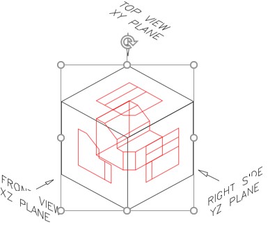
Inventor has p three predefined planes that can be used to draw the Base sketch. They are the XY, XZ, and YZ planes. The XY plane is the Top view, the XZ plane is the Front view and the YZ is the Right Side view of the model.
Keep in mind the rule that was taught in Module 4. ‘ It is best to draw the Base sketch on the plane that has the most complex contour. Contours with arcs and curves should be avoided ‘.
The Three Predefined Planes
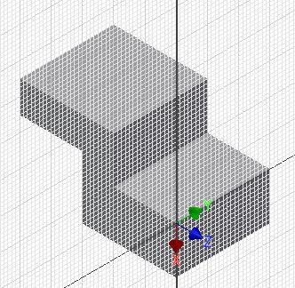
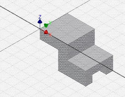
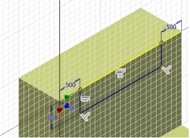
To help visualize the three predefined planes used in Inventor, the 3D model shown in Figure 10-1 is used in this module. The glass box principle that was taught in Module 8 is used to help you visualize Inventor’s three predefined planes. See Figure 10-2.
The 3D Model
Consumed and Unconsumed Sketches
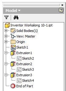
A consumed sketch is a 2D sketch that has been extruded or revolved to create a 3D solid model. An unconsumed sketch is a 2D sketch that is blank or one that has not been extruded or revolved.
The Browser bar will display which sketches have been consumed and which ones are unconsumed. See Figure 10-3. Sketch1 is unconsumed while Sketch2, Sketch3, and Sketch4 have been extruded and are consumed.
Consumed and Unconsumed Sketches
USER TIP: A 2D sketch can be drawn in the orthographic view or in the 3D Home view. In fact, any 3D orbited view can be used. When drawing in a 3D view, it is always best to draw in the Home view since this helps you maintain a good mental picture of the model.
WORK ALONG: Working with 2D Sketching Planes
Step 1
Start a new part file using the template: English-Modules Part (in).ipt.
Step 2
In Sketch mode, press F6 to change to the Home view. The Graphic window and the Browser bar will appear as shown in the figure. (Figure Step 2)
Step 3
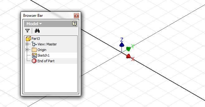
In the Browser bar, expand the folder: Origin as shown in the figure. Place the cursor on the XY Plane. Note the orientation of the plane on the sketch. (Figure Step 3)

Step 4
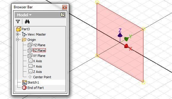
Place the cursor on the XZ Plane in the Browser bar. Note the orientation of the plane on the sketch. The XZ Plane is the Front view. (Figure Step 4)
Step 5
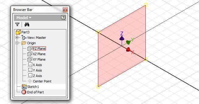
Place the cursor on the YZ Plane in the Browser bar. Note the orientation of the plane on the sketch. This is the Right Side view. (Figure Step 5)
Step 6
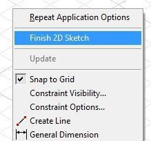
Place the cursor anywhere in the Graphic window and right click the mouse. In the Right-click menu, click Finish 2D Sketch.
3D Model – Home View
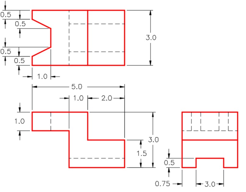
Dimensioned Multiview Drawing [Click to see image full size]
Step 7
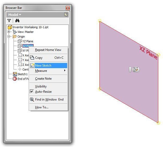
Save the part file with the name: Inventor Workalong 10-1. In Model mode, expand the folder: Origin in the Browser bar and right-click the XZ plane. In the Right-click menu, click New Sketch as shown in figure. (Figure Step 7)
Step 8
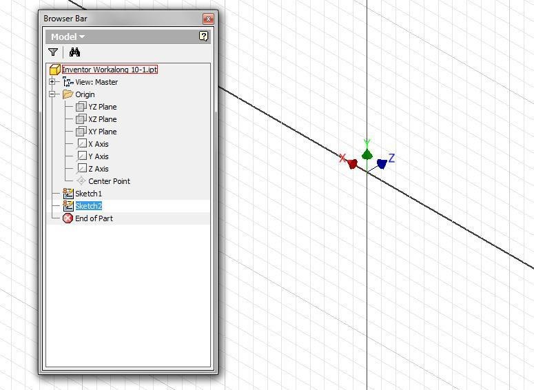
The Graphic window will change to Sketch mode. Change to the Home view. Note that in the Browser bar a new sketch will appear and named Sketch2. (Figure Step 8)
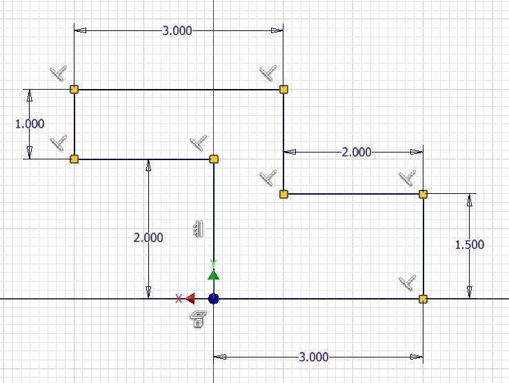
Step 9
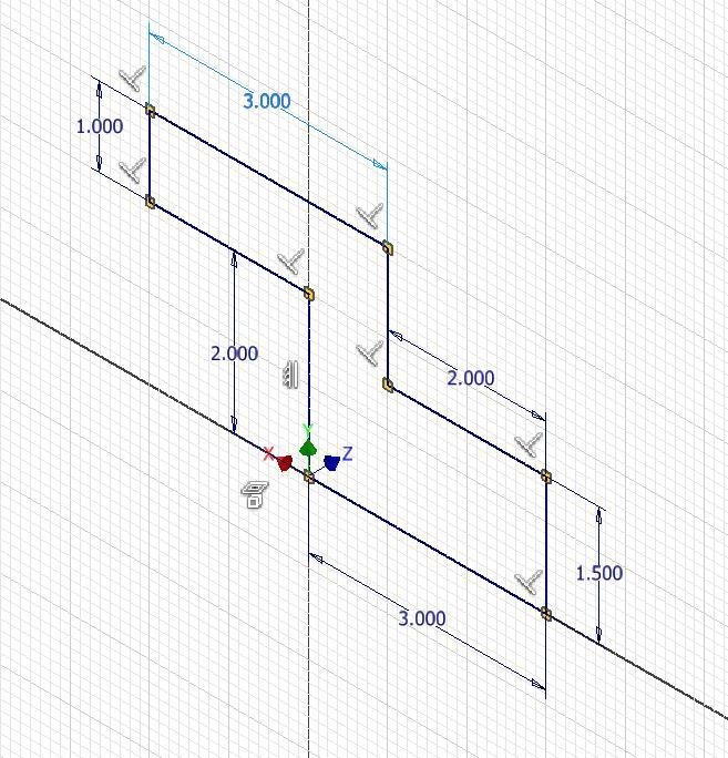
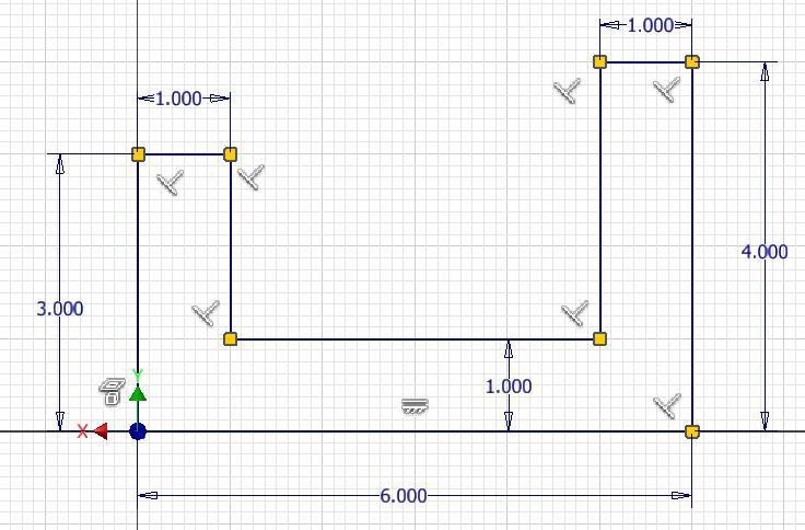
Project the Center Point onto the sketch plane. Draw the Base sketch for the model applying all of the necessary geometrical constraints to maintain the shape of the sketch. Note the location of X0Y0Z0. Insert the necessary driving dimensions to fully constrain the sketch. (Figure Step 9)
Step 10
Press PAGE UP key to execute the LOOK UP/VIEW FACE command. Select one of the lines to change the sketch to the 2D view of the the XZ plane. Press F8 to display the geometrical constraint icons. They should appear similar to the figure. (Figure Step 10)
Step 11
Right-click anywhere in the Graphic window. In the Right-click menu, click Finish 2D Sketch to return to Model mode. (Figure Step 11)
Step 12
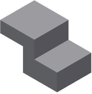
Save the part with the name: Inventor Workalong 10-1. Extrude the sketch to create the solid model as shown in figure. (Figure Step 12)
Step 13
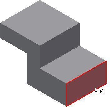
Using the 2D SKETCH command, or even better the shortcut S, start a new sketch and select the right side as the plane to draw it on. (Figure Step 13)
Step 14
The grid will display on the right side. It will be Sketch3 in the Browser bar. (Figure Step 14)
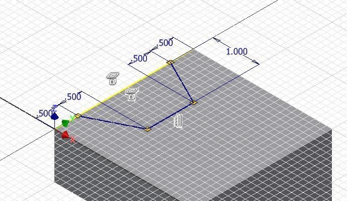
Step 15
Draw three lines for the slot. Apply all of the necessary geometrical and dimensional constraints to fully constrain the sketch. (Figure Step 15)
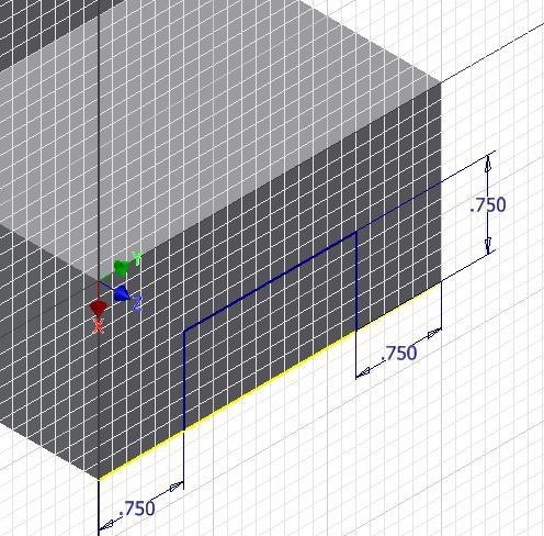
Step 16
Press F8 to enable the display of the constraint icons. They should be similar to the figure. (Figure Step 16)
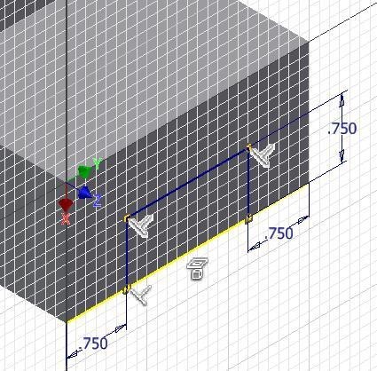
Step 17
Press F9 to disable the display of the constraint icons. Extrude the sketch using the To next. (Figure Step 17)
Step 18
Start a new sketch on the top plane as shown in the figure. (Figure Step 18)
Step 19
Draw the 2D sketch on the new sketching plane and insert the necessary dimensions to fully constrain it. (Figure Step 19)
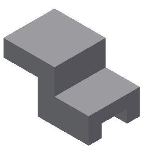
Step 20
Extrude the top sketch to complete the solid model. (Figure Step 20)
Step 21
Change the view to the Home view and apply the color: Chrome – Polished Black. Orbit the model to check the bottom. (Figure Step 21)
Step 22
Save and close the file.
Key Principles
Key Principles in Module 10
- Inventor has three predefined planes that can be used to draw the Base sketch on. They are the XY, XZ and YZ planes. The XY plane is the Top view, the XZ plane is the Front view, and the YZ is the Right Side view of the Base model.
- A consumed sketch is a 2D sketch that has been extruded or revolved. An unconsumed sketch is a 2D sketch that is blank or one that has not been extruded or revolved.
Lab Exercise 10-1
Time allowed: 45 minutes.
| Part Name | Project | Units | Template | Color | Material |
| Inventor Lab Lab 10-1 | Inventor Course | Inches | English-Modules Part (in).ipt | Titanium – Polished | N/A |
Step 1
Project the Center Point onto the base sketching plane.
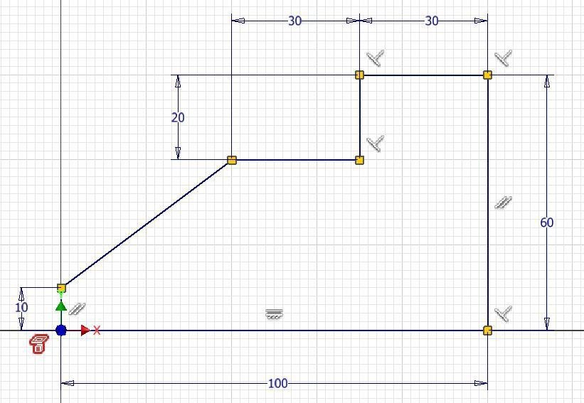
Step 2
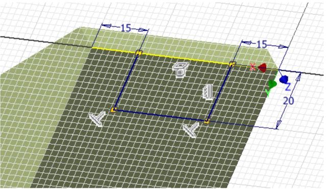
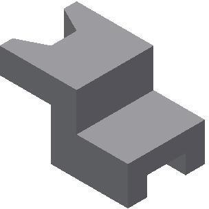
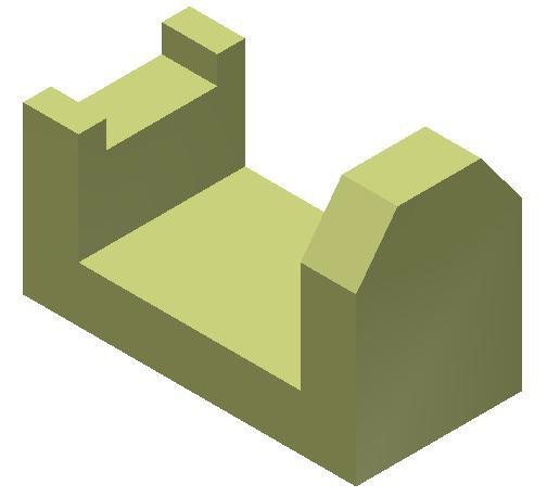
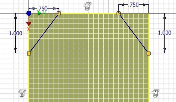
Note the location of X0Y0Z0. Draw the necessary sketches and extrude them to produced the solid model shown below. Apply all of the necessary geometrical and dimensional constraints to fully constrain all sketches. (Figure Step 2A and 2B)
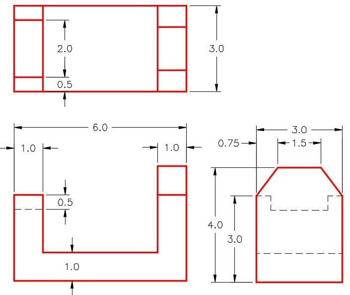
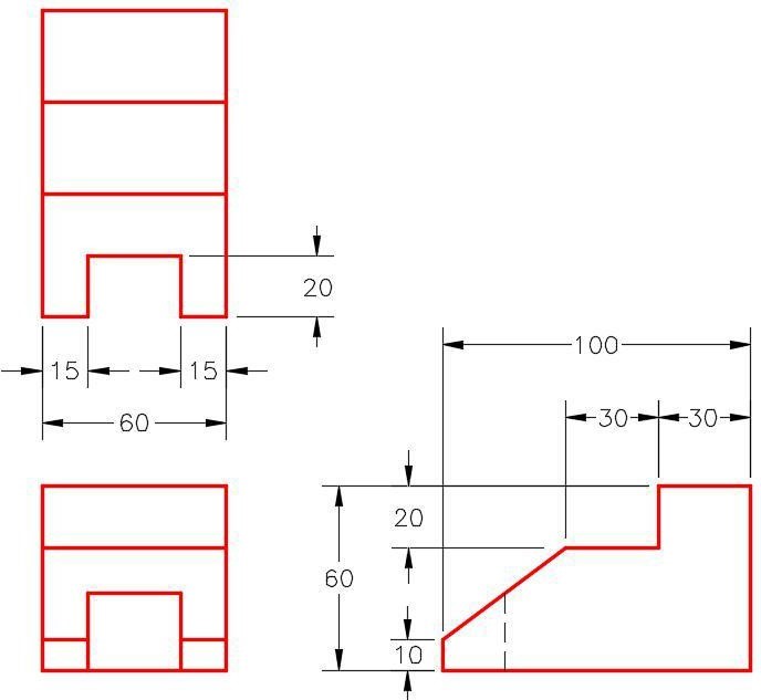
Dimensioned Multiview Drawing [Click to see image full size]
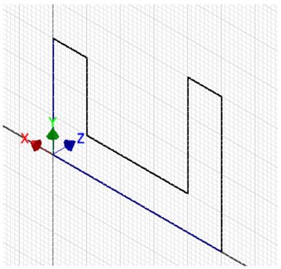
Suggested Base Sketch – Front XZ Plane
Step 3
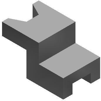
Apply the colour as shown above. (Figure Step 3)
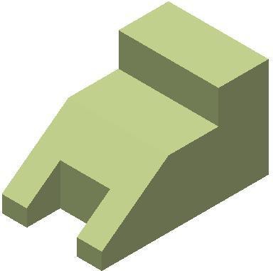
Lab Exercise 10-2
Time allowed: 45 minutes.
| Part Name | Project | Units | Template | Color | Material |
| Inventor Lab Lab 10-2 | Inventor Course | Millimeters | Metric-Modules Part (mm).ipt | Zinc Chromate 2 | N/A |
Step 1
Project the Center Point onto the base sketching plane.
Step 2
Note the location of X0Y0Z0. Draw the necessary sketches and extrude them to produced the solid model. Apply all of the necessary geometrical and dimensional constraints to fully constrain all sketches. (Figure Step 2A and 2B)
Dimensioned Multiview Drawing [Click to see image full size]
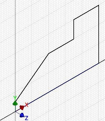
Suggested Base Sketch – Right Side YZ Plane
Step 3
Apply the colour shown above. (Figure Step 3)