Mechanical Cooling
35 The DX Cooling Cycle
Click play on the following audio player to listen along as you read this section.
https://video.bccampus.ca/id/0_k4cxzrv8?width=608&height=70&playerId=23448552
A step-by-step analysis of the forces acting upon the refrigerant as it passes through each of the four main components of a DX cooling system will help in our understanding of the process.
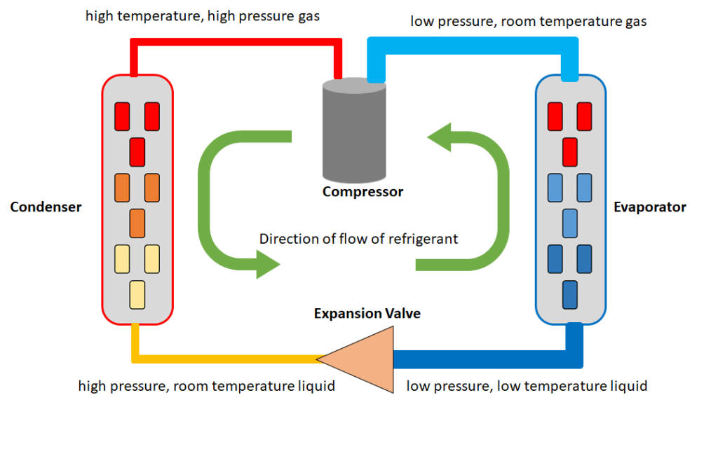
The Compressor
This is the component which drives the refrigerant throughout the system. It receives a low pressure, room temperature gas, and pumps the refrigerant through a valve into a much narrower diameter pipe and this restriction in volume, combined with the increased pressure of the refrigerant causes its temperature to rise rapidly. The refrigerant is a high temperature, high pressure gas as it is exiting the compressor valve.
The Condenser
As the refrigerant enters the condenser coil it is a high temperature, high pressure gas. The condenser coil has a large surface area that is exposed to the air. It will often be attached to a large metal grill to increase its available surface area, dissipating heat through conduction as well as convection. The refrigerant dissipates the thermal energy and condenses into a liquid as it moves through the coil. Most of the heat energy is dissipated at this stage, utilizing the Second Law of Thermodynamics to transfer heat from the refrigerant to the surrounding air. A fan can be incorporated into the cooling system to help circulate air across the condenser coils and take heat away from the system. Condenser units are often installed outdoors on rooftops for convenient heat dissipation.
The Expansion Valve
This component regulates the flow of refrigerant from the high pressure/temperature side of the system and the low pressure/temperature side. As the refrigerant enters the expansion valve it is a high pressure, room temperature liquid, and as it expands into the larger area beyond the valve, its pressure, and thus its temperature drops dramatically. This is when the refrigerant is at its coldest, as a low pressure, low temperature liquid. The amount of refrigerant that the valve lets through is controlled by a diaphragm, which is connected to a capillary type thermal sensor filled with a separate refrigerant. The sensing bulb is attached to the exit line of the evaporator. By sensing the temperature of the refrigerant as it leaves the evaporator, the expansion valve can let in more or less refrigerant at a given moment, thus raising or lowering the temperature of the refrigerant as it enters the evaporator.
The Evaporator
The evaporator coils are similar in design to the condenser coils but with the purpose of drawing heat from the surrounding air into the refrigerant. Again a large surface area helps to conduct heat from the air to the refrigerant. Fans can be used circulate the air and replace cooled air with warmer air. As the low pressure, low temperature liquid enters the evaporator coil and starts to absorb heat, it rapidly evaporates from a liquid to a gas. This phase shift draws energy from the surrounding air in the form of heat, and carries it away as the low pressure, room temperature gas is suctioned towards the compressor, where energy is added to drive the cycle again.
A material used in DX cooling systems that boils below room temperature, and is used to transfer thermal energy from one point to another.
A mechanical cooling system that uses the evaporation and condensation of a refrigerant to remove heat from an area.
A component which allows a refrigerant to rapidly condense and dissipate thermal energy into the environment. Will incorporate coils to maximize surface area to volume ratio.
Thermal energy always flows spontaneously in the form of heat from regions of higher temperature to regions of lower temperature, increasing the entropy of the system.
A component which allows a refrigerant to rapidly boil and absorb thermal energy from a room or area. Will incorporate coils to maximize surface area to volume ratio.
