45 Schematic Diagrams vs Wiring Diagrams
Aaron Lee
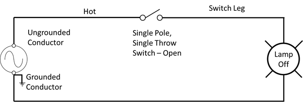
One of the most frequently used diagrams in motor control work is the schematic diagram. This diagram uses symbols to identify components and interconnecting lines to display the electrical continuity of a circuit.
Schematic diagrams show how a circuit works logically and electrically. When troubleshooting or designing control circuits, we use “ladder” or “schematic” diagrams to represent how the circuit works but these diagrams do not show how equipment is physically laid out, nor do they represent how things are wired “in the real world.” Two components might be right next to each other on the ladder diagram and 50 metres apart in the real world.
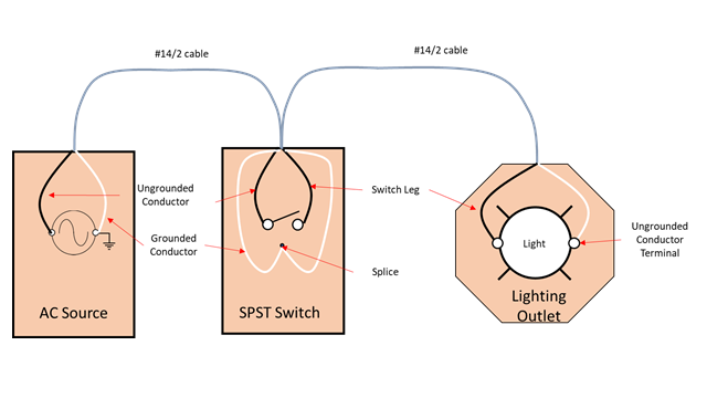
Wiring diagrams, also called connection diagrams, however, do show how equipment is laid out and the connections between them. A wiring diagram shows the relative layout of the components and the wire connections between them. This type of diagram shows the physical relation of all devices in the system, the conductor terminations between these devices, and are commonly used in motor control installations.