Diagrams
23 Motor-Lead Connections
Three-phase motors use coils of wire to create magnetic fields and produce rotation.
Standard 3-phase motors use six individual coils, two for each phase. The internal construction and connection of these coils inside of the motor is predetermined when the motor is manufactured. There are two classes of 3-phase motors: Wye and Delta.

Three-phase motors are also constructed to operate at two different voltages, and so the coils can be connected in either their high-voltage or low-voltage configurations.
In the high-voltage configuration, the two coils of each phase are connected in series with each other so that the higher value of supply voltage is split equally between them and rated current is drawn through each winding.
In the low-voltage configuration, the two coils of each phase are connected in parallel with each other so that the lower value of supply voltage is shared equally between the coils and rated current is drawn through each winding.
Note that the low-voltage connection will necessarily need to draw twice as much current from the source as the high-voltage connection. Most motors will list two values of voltage and current on their nameplates. It is important to size motor starters and their overload relays based on the expected value of current that is to be drawn by the motor at the voltage it is used at.
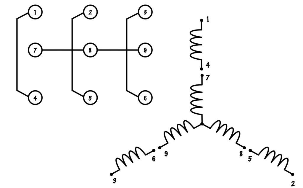
Each of the six individual coils has two leads supplying it, for a total of twelve leads in total. In both the Wye and Delta configurations, three of these leads are connected internally, and so only nine leads are brought out of the motor for connection. These leads are numbered 1–9, and in both Wye and Delta follow a standard numbering convention: starting at the top of the diagram with wire number 1, draw an inwardly descending spiral from each connection point, ascending to the next number at each step.
Depending upon the internal construction of the motor, these leads can be hooked up in one of four ways: High- or low-voltage Wye, or high- or low-voltage Delta
Identifying Wye or Delta with an Ohmmeter
It sometimes becomes necessary to test or confirm the configuration of a motor before final connection. If a Wye wound motor is connected as a Delta wound motor or vice versa, the motor will not operate properly.
Consider this situation: You have nine leads coming from a motor, but no indication of whether its Wye or Delta wound. By using an ohmmeter to do a simple continuity check, you can determine the construction type of the motor.
If it is Wye wound, each of wires 1, 2, and 3 should only have continuity with one other lead (4, 5 and 6 respectively). The three leads without continuity to wires 1, 2, and 3 should all have continuity with each other.
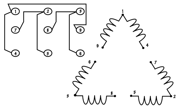
If it is Delta wound, each of wires 1, 2, and 3 should have continuity with two other leads:
- T1 has continuity to T4 &T9
- T2 has continuity to T5 &T7
- T3 has continuity to T6 &T8
It is important to note that these points represent the internal connection of the coils of the motor, not how they are to be hooked up to voltage.
Wye Connections
Low-voltage Wye
In this configuration, each phase is brought to two coils that are connected in parallel with each other. Terminals 4, 5, and 6 are tied together to make a second neutral connection.

| L1 | L2 | L3 | Tie together |
| 1,7 | 2,8 | 3,9 | 4,5,6 |
High-voltage Wye
In this configuration, each phase is brought to two coils that are connected in series with one another. 
Wye motor high-voltage connection.
| L1 | L2 | L3 | Tie together |
| 1 | 2 | 3 | 4,7 – 5,8 – 6,9 |
Delta Connections
Low-voltage Delta
In this configuration, each phase is brought to centre connection of two coils and to the end connections of each of the other two groups of coils. 
Delta Motor Low Voltage Connection
| L1 | L2 | L3 | Tie together |
| 1,6,7 | 2,4,8 | 3,5,9 | none |
High Voltage Delta
In this configuration each phase is brought to two coils that are connected in series with the other phases coils. 
Delta Motor High Voltage Connection
| L1 | L2 | L3 | Tie together |
| 1 | 2, | 3 | 4,7 – 5,8 – 6,9 |
The difference in electric potential between two points, which is defined as the work needed per unit of charge to move a test charge between the two points. It is measured in volts (V).
In electrical terms, refers to a connection where current has only one path to flow.
Loads connected in series will have the the same value of current flowing through them, and share the total voltage between them. Switches and overcurrent equipment is connected in series with equipment to control and protect it.
In electrical terms, refers to a connection where current has more than one path to flow.
Loads connected in parallel will experience the same potential difference (voltage), but may draw different values of current depending upon their individual resistance.
A device that controls the flow of electrical power to a motor. It is designed to safely start and stop a motor, and provide overload protection.
A heater element paired with normally-closed contacts that open once the heater gets too hot. Two types of relays are the bimetallic strip and the melting solder pot.
A device used to measure the resistance of a circuit. Ohmmeters must not be used on live circuits. Ohmmeters connect a small internal voltage source to the circuit that is being measured or tested, and determine the value of resistance or continuity by measuring what value of current flows through the meter.
Can be either digital or analogue.
