Chapter 8 Statics and Torque
8.3 Applications of Statics and Problem-Solving Strategies
Summary
- Discuss the applications of Statics in real life.
- State and discuss various problem-solving strategies in Statics.
Statics can be applied to a variety of situations, ranging from raising a drawbridge to bad posture and back strain. We begin with a discussion of problem-solving strategies specifically used for statics. Since statics is a special case of Newton’s laws, both the general problem-solving strategies and the special strategies for Newton’s laws, discussed in Chapter 4.7 Problem-Solving Strategies, still apply.
PROBLEM-SOLVING STRATEGY: STATIC EQUILIBRIUM SITUATIONS
- The first step is to determine whether or not the system is in static equilibrium. This condition is always the case when the acceleration of the system is zero and accelerated rotation does not occur.
- It is particularly important to draw a free body diagram for the system of interest. Carefully label all forces, and note their relative magnitudes, directions, and points of application whenever these are known.
- Solve the problem by applying either or both of the conditions for equilibrium (represented by the equations net F = 0 and net τ =0, depending on the list of known and unknown factors. If the second condition is involved, choose the pivot point to simplify the solution. Any pivot point can be chosen, but the most useful ones cause torques by unknown forces to be zero. (Torque is zero if the force is applied at the pivot (then r = 0), or along a line through the pivot point (then θ = 0). Always choose a convenient coordinate system for projecting forces.
- Check the solution to see if it is reasonable by examining the magnitude, direction, and units of the answer. The importance of this last step never diminishes, although in unfamiliar applications, it is usually more difficult to judge reasonableness. These judgments become progressively easier with experience.
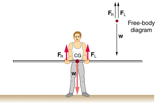
Now let us apply this problem-solving strategy for the pole vaulter shown in the three figures below. The pole is uniform and has a mass of 5.00 kg. In Figure 1, the pole’s cg lies halfway between the vaulter’s hands. It seems reasonable that the force exerted by each hand is equal to half the weight of the pole, or 24.5 N. This obviously satisfies the first condition for equilibrium (net F = 0). The second condition (net τ = 0) is also satisfied, as we can see by choosing the cg to be the pivot point. The weight exerts no torque about a pivot point located at the cg, since it is applied at that point and its lever arm is zero. The equal forces exerted by the hands are equidistant from the chosen pivot, and so they exert equal and opposite torques. Similar arguments hold for other systems where supporting forces are exerted symmetrically about the cg. For example, the four legs of a uniform table each support one-fourth of its weight.
In Figure 1, a pole vaulter holding a pole with its cg halfway between his hands is shown. Each hand exerts a force equal to half the weight of the pole, FR = FL = w/2. (b) The pole vaulter moves the pole to his left, and the forces that the hands exert are no longer equal. See Figure 1. If the pole is held with its cg to the left of the person, then he must push down with his right hand and up with his left. The forces he exerts are larger here because they are in opposite directions and the cg is at a long distance from either hand.
Similar observations can be made using a meter stick held at different locations along its length.
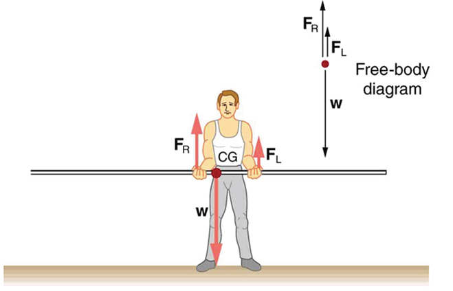
If the pole vaulter holds the pole as shown in Figure 2, the situation is not as simple. The total force he exerts is still equal to the weight of the pole, but it is not evenly divided between his hands. (If FL = FR, then the torques about the cg would not be equal since the lever arms are different.) Logically, the right hand should support more weight, since it is closer to the cg. In fact, if the right hand is moved directly under the cg, it will support all the weight. This situation is exactly analogous to two people carrying a load; the one closer to the cg carries more of its weight. Finding the forces FL and FR is straightforward, as the next example shows.
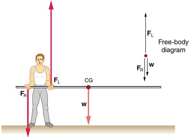
If the pole vaulter holds the pole from near the end of the pole (Figure 3), the direction of the force applied by the right hand of the vaulter reverses its direction.
Example 1: What Force Is Needed to Support a Weight Held Near Its CG?
For the situation shown in Figure 2, calculate: (a) FR, the force exerted by the right hand, and (b) FL, the force exerted by the left hand. The hands are 0.900 m apart, and the cg of the pole is 0.600 m from the left hand.
Strategy
Figure 2 includes a free body diagram for the pole, the system of interest. There is not enough information to use the first condition for equilibrium (net F = 0), since two of the three forces are unknown and the hand forces cannot be assumed to be equal in this case. There is enough information to use the second condition for equilibrium (net τ = 0) if the pivot point is chosen to be at either hand, thereby making the torque from that hand zero. We choose to locate the pivot at the left hand in this part of the problem, to eliminate the torque from the left hand.
Solution for (a)
There are now only two nonzero torques, those from the gravitational force (τw) and from the push or pull of the right hand (τR). Stating the second condition in terms of clockwise and counterclockwise torques,
or the algebraic sum of the torques is zero.
Here this is
since the weight of the pole creates a counterclockwise torque and the right hand counters with a clockwise torque. Using the definition of torque, τ = rF sin θ, noting that θ = 90°, and substituting known values, we obtain
Thus,
Solution for (b)
The first condition for equilibrium is based on the free body diagram in the figure. This implies that by Newton’s second law:
From this we can conclude:
Solving for FL, we obtain
Discussion
FLis seen to be exactly half of FR, as we might have guessed, since FL is applied twice as far from the cg as FR.
If the pole vaulter holds the pole as he might at the start of a run, shown in Figure 3, the forces change again. Both are considerably greater, and one force reverses direction.
TAKE-HOME EXPERIMENT
This is an experiment to perform while standing in a bus or a train. Stand facing sideways. How do you move your body to readjust the distribution of your mass as the bus accelerates and decelerates? Now stand facing forward. How do you move your body to readjust the distribution of your mass as the bus accelerates and decelerates? Why is it easier and safer to stand facing sideways rather than forward? Note: For your safety (and those around you), make sure you are holding onto something while you carry out this activity!
PHET EXPLORATIONS: BALANCING ACT
Play with objects on a teeter totter to learn about balance. Test what you've learned by trying the Balance Challenge game.
Summary
- Statics can be applied to a variety of situations, ranging from raising a drawbridge to bad posture and back strain. We have discussed the problem-solving strategies specifically useful for statics. Statics is a special case of Newton’s laws, both the general problem-solving strategies and the special strategies for Newton’s laws, discussed in Chapter 4.7 Problem-Solving Strategies, still apply.
Glossary
- static equilibrium
- equilibrium in which the acceleration of the system is zero and accelerated rotation does not occur
Conceptual Questions
1: When visiting some countries, you may see a person balancing a load on the head. Explain why the center of mass of the load needs to be directly above the person’s neck vertebrae.
Problems & Exercises
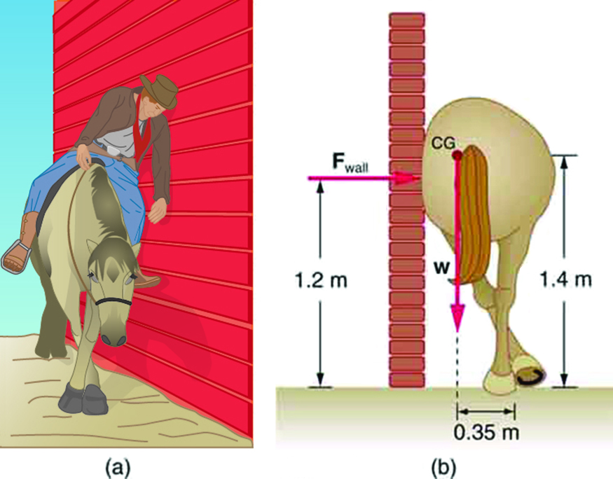
1: Suppose a horse leans against a wall as in Figure 10. Calculate the force exerted on the wall assuming that force is horizontal while using the data in the schematic representation of the situation. Note that the force exerted on the wall is equal in magnitude and opposite in direction to the force exerted on the horse, keeping it in equilibrium. The total mass of the horse and rider is 500 kg. Take the data to be accurate to three digits.
2: Two children of mass 20.0 kg and 30.0 kg sit balanced on a seesaw with the pivot point located at the center of the seesaw. If the children are separated by a distance of 3.00 m, at what distance from the pivot point is the small child sitting in order to maintain the balance?
3: (a) Calculate the magnitude and direction of the force on each foot of the horse in Figure 10 (two are on the ground), assuming the center of mass of the horse is midway between the feet. The total mass of the horse and rider is 500kg. (b) What is the minimum coefficient of friction between the hooves and ground? Note that the force exerted by the wall is horizontal.
4: A person carries a plank of wood 2.00 m long with one hand pushing down on it at one end with a force F1 and the other hand holding it up at .500 m from the end of the plank with force F2. If the plank has a mass of 20.0 kg and its center of gravity is at the middle of the plank, what are the magnitudes of the forces F1 and F2?
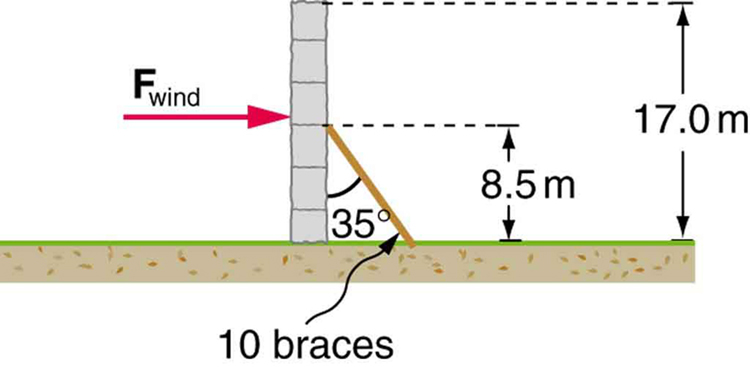
5: A 17.0-m-high and 11.0-m-long wall under construction and its bracing are shown in Figure 11. The wall is in stable equilibrium without the bracing but can pivot at its base. Calculate the force exerted by each of the 10 braces if a strong wind exerts a horizontal force of 650 N on each square meter of the wall. Assume that the net force from the wind acts at a height halfway up the wall and that all braces exert equal forces parallel to their lengths. Neglect the thickness of the wall.
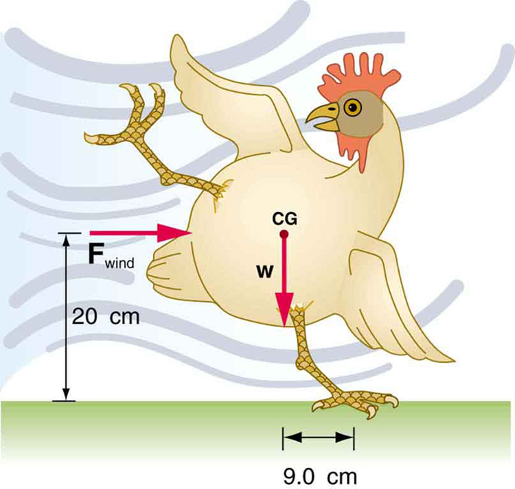
6: (a) What force must be exerted by the wind to support a 2.50-kg chicken in the position shown in Figure 12? (b) What is the ratio of this force to the chicken’s weight? (c) Does this support the contention that the chicken has a relatively stable construction?
7: Suppose the weight of the drawbridge in Figure 13 is supported entirely by its hinges and the opposite shore, so that its cables are slack. (a) What fraction of the weight is supported by the opposite shore if the point of support is directly beneath the cable attachments? (b) What is the direction and magnitude of the force the hinges exert on the bridge under these circumstances? The mass of the bridge is 2500 kg.
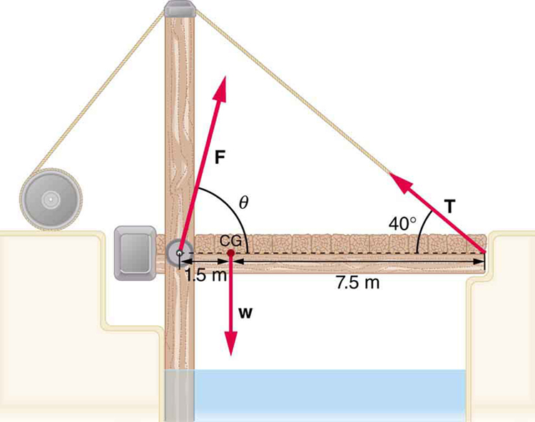
8: Suppose a 900-kg car is on the bridge in Figure 13 with its center of mass halfway between the hinges and the cable attachments. (The bridge is supported by the cables and hinges only.) (a) Find the force in the cables. (b) Find the direction and magnitude of the force exerted by the hinges on the bridge.
9: A sandwich board advertising sign is constructed as shown in Figure 14. The sign’s mass is 8.00 kg. (a) Calculate the tension in the chain assuming no friction between the legs and the sidewalk. (b) What force is exerted by each side on the hinge?
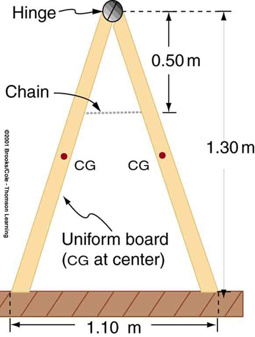
10: (a) What minimum coefficient of friction is needed between the legs and the ground to keep the sign in Figure 14 in the position shown if the chain breaks? (b) What force is exerted by each side on the hinge?
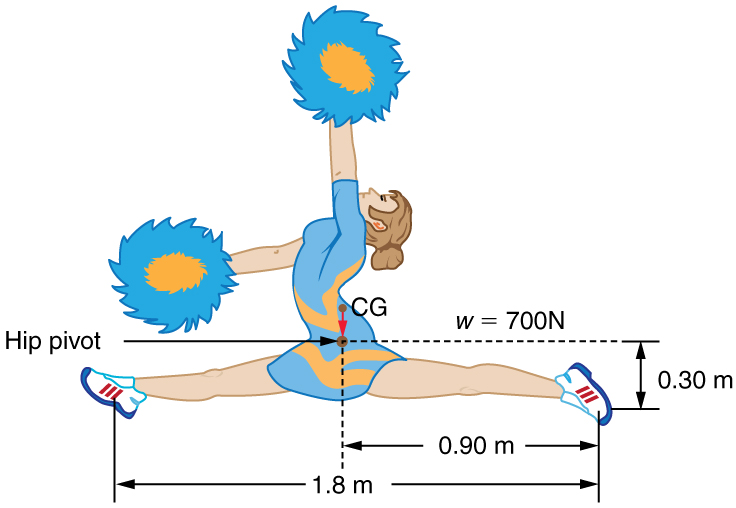
11: A gymnast is attempting to perform splits. From the information given in Figure 15, calculate the magnitude and direction of the force exerted on each foot by the floor.
12: To get up on the roof, a person (mass 70.0 kg) places a 6.00-m aluminum ladder (mass 10.0 kg) against the house on a concrete pad with the base of the ladder 2.00 m from the house. The ladder rests against a plastic rain gutter, which we can assume to be frictionless. The center of mass of the ladder is 2 m from the bottom. The person is standing 3 m from the bottom. What are the magnitudes of the forces on the ladder at the top and bottom?
13: In Figure 3, the cg of the pole held by the pole vaulter is 2.00 m from the left hand, and the hands are 0.700 m apart. Calculate the force exerted by (a) his right hand and (b) his left hand. (c) If each hand supports half the weight of the pole in Figure 1, show that the second condition for equilibrium (net τ = 0) is satisfied for a pivot other than the one located at the center of gravity of the pole. Explicitly show how you follow the steps in the Problem-Solving Strategy for static equilibrium described above.
Problems & Exercises
1: To get up on the roof, a person (mass 70.0 kg) places a 6.00-m aluminum ladder (mass 10.0 kg) against the house on a concrete pad with the base of the ladder 2.00 m from the house. The ladder rests against a plastic rain gutter, which we can assume to be frictionless. The center of mass of the ladder is 2 m from the bottom. The person is standing 3 m from the bottom. What are the magnitudes of the forces on the ladder at the top and bottom?
2: In Figure 3, the cg of the pole held by the pole vaulter is 2.00 m from the left hand, and the hands are 0.700 m apart. Calculate the force exerted by (a) his right hand and (b) his left hand. (c) If each hand supports half the weight of the pole in Figure 1, show that the second condition for equilibrium (net τ = 0) is satisfied for a pivot other than the one located at the center of gravity of the pole. Explicitly show how you follow the steps in the Problem-Solving Strategy for static equilibrium described above.
Solutions
Problems & Exercises
1: Fwall = 1.43 x 10³ N
3: (a) 2.55 x 10³ N, 16.3o to the left of vertical (i.e, toward the wall) (b) 0.292
5: FB = 2.12 x 10⁴ N
7: (a) 0.167, or about one-sixth of the weight is supported by the opposite shore. (b) F = 2.0 x 10⁴ N straight up.
9: (a) 21.6 N (b) 21.6 N
11: 350 N directly upwards
