Main Body
2
Learning Objectives
After completing this chapter you should be able to:
- Define normal and shear stress and strain
- Discuss the relationship between design stress, yield stress and ultimate stress
- Design members under tension, compression and shear loads
- Determine members deformation under tension and compression
Mechanical Stress
This section discusses the effects of mechanical loads (forces) acting on members. Chapter 3 will cover the effects of thermal loads (thermal expansion).
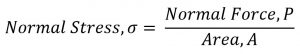
Tension or compression in a member generate normal stresses; they are called “normal” because the cross-section that resists the load is perpendicular (normal) to the direction of the applied forces. Both tensile and compressive stresses are calculated with:
If a member has a variable cross-section, the area that must be used in calculations is the minimum cross-sectional area; this will give you the maximum stress in the member, which ultimately will govern the design.
Shear stresses
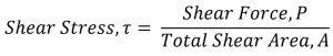
In shear the cross-section area that resists the load is parallel with the direction of applied forces. In addition to that, when estimating the shear area you must factor in how many cross-sections contribute to the overall strength of the assembly.
For instance, if you consider the pin of a door hinge as subjected to a shear load, you have to count how many cross-sections resist the load.
The formula for calculating the shear stress is the same:
In a punching operation the area that resists the shear is in the shape of a cylinder for a round hole (think of a cookie cutter). Therefore the area in shear will be found from multiplying the circumference of the shape by the thickness of the plate.
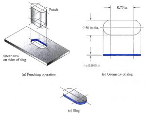
Hint: when looking at textbook figures you will observe that two forces are indicated. This does not mean that the force you use in the formula is (2 × Force P), but simply indicates that one is the Action force and the second one is the Reaction.
Strain and Modulus of Elasticity
Normal Strain
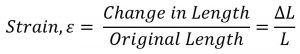
A member in tension or compression will elastically deform proportional with, among other parameters, the original length. Strain, also called unit deformation, is a non-dimensional parameter expressed as:
If you choose to use a negative value for compression strain (reduction in length) then you must also express the equivalent compression stress as a negative value.
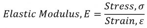
The stress – strain curve is generated from the tensile test. Over the elastic region of the graph the deformation is direct proportional with the load. Dividing the load by the cross-section area (constant) and the deformation by the original length (constant) leads to a graphical representation of Strain vs. Stress. The constant ratio of stress and strain is Young’s Modulus or Elastic Modulus, a property of each material.
Reasonable Answers
When solving normal stress – strain problems, especially in the SI system, you may be able to judge if your answers are reasonable or not. Consider the following example:
A 1 m long, 20 mm diameter, A 36 Carbon Steel bar (Yield strength 248 MPa, Ultimate strength 400 MPa, Elastic Modulus =200 GPa) suspends a 6 metric tons load. Evaluate the stress and the strain in the bar.
