LEARNING TASK 7 : Describe lockout and tagout (LOTO) procedures
Lockout equipment
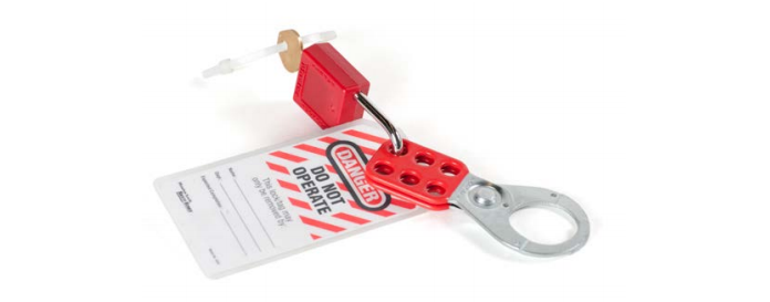
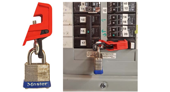
There are many different types of locking systems. Put your personal lock on the switch using a scissor adapter or hasp as shown in Figure 1. While this figure shows a single safety hasp and lock, it is also common to use more than one hasp when locking out.
Chains and/or cables
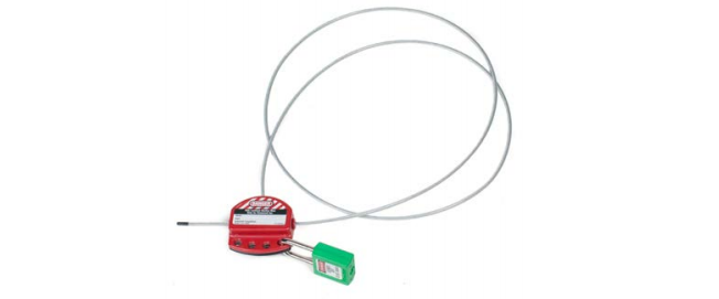
If you need to lock out equipment with more than one energy source, instead of using several locks you could use a lockout cable to lockout several disconnect switches (Figure 2). This cable would be run through the locking hole in each of the safety disconnects you are locking out. The cable diameter must be large enough to prevent the safety disconnect switches from being operated accidentally. A scissor lock adapter can be used to apply multiple locks.
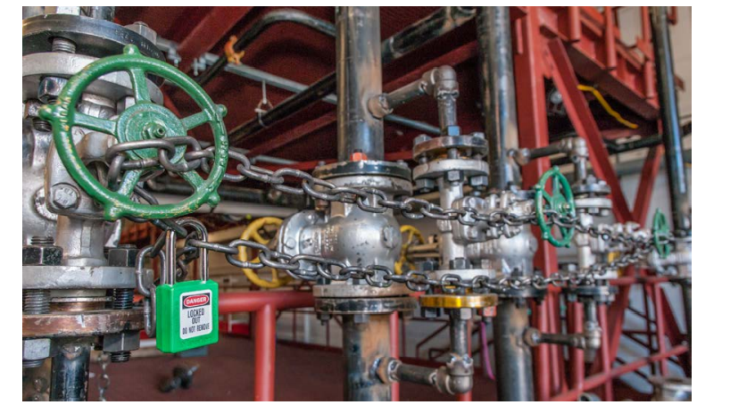
Chains and cables can also be used to make valve handles inoperable (Figure 3).
Tags, locks, and scissors
Lockout devices must provide a visual verification, must be locked as required, and must have a “DO NOT OPERATE” tag placed on them. The tag must have on it your name, the date and time, and the location and identity of the equipment being worked on.
Lockout for circuit breakers
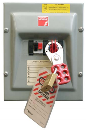
Lock out the desired breaker. If there is access to the main breaker or disconnect that kills all power to the panel, and if no other workers need to lock out in that panel, then you may lock the panel door closed (Figure 5).
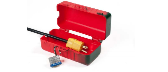
Cord locks
For plugged-in equipment, if the male end of the plug is in view and you do not leave the machine until you have finished working, a lock is not needed. If the plug is not in view, use an adapter and lock, or lock the cord to an object to prevent it from being reconnected to the circuit. Figure 6 shows a power cord plug lock.
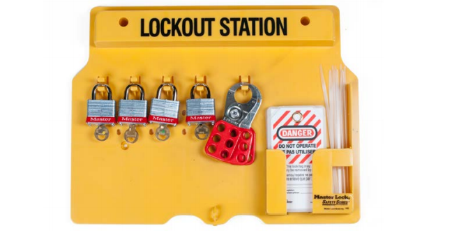
Lockout station
A lockout station has keyed locks to be used only for equipment lockout. It also contains tags and lockout devices. Locks have one key that is kept with the installer of the lock. Once the work procedure is completed, the lock and key should be returned to the lockout station. These stations can be portable or mounted permanently to the wall where required.
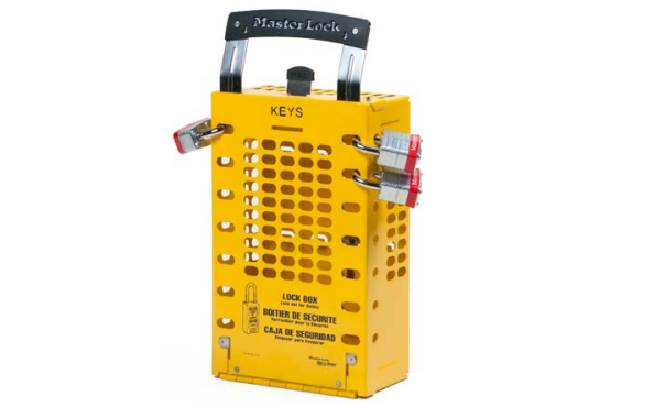
Key box system
Machines are often powered by several sources, so situations can arise where a single job requires you to lock out more than one power source. This can be done efficiently and safely with a key box system.
A key box is a box mounted on a wall, containing two sets of locks. Lock set A is mastered to a single key and lock set B is mastered to a different single key. The key box is treated as a locked-out power source. All the regulations of a lockout apply to the key box. A key box lockout procedure checklist must be posted at the key box. Also, other workers may add their locks to the key box.
Spades and blinds
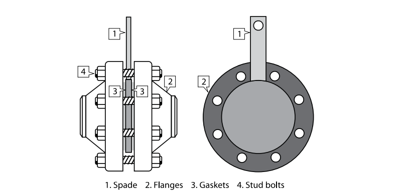
In the context of lockout, a spade is a round plate with a small tab that is placed between two pipe flanges in order to lock out certain piping sections, and is sometimes referred to as a frying pan (Figure 9). The spade prevents cross-contamination and also allows work to be done on individual piping sections. The small tab lets workers see that the spade is in place, in the same way an indicator valve allows workers see whether a valve is in the open or closed position.
A blind flange (Figure 10) is used when the end of the pipe or valve is removed. An open flange can be closed off with a blind flange.