7.6 Molecular Structure and Polarity
Learning Objectives
By the end of this section, you will be able to:
- Predict the structures of small molecules using valence shell electron pair repulsion (VSEPR) theory
- Explain the concepts of polar covalent bonds and molecular polarity
- Assess the polarity of a molecule based on its bonding and structure
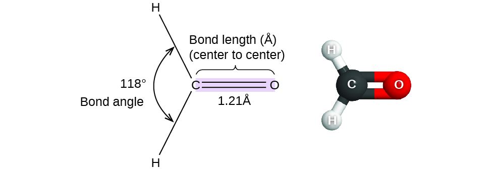
Thus far, we have used two-dimensional Lewis structures to represent molecules. However, molecular structure is actually three-dimensional, and it is important to be able to describe molecular bonds in terms of their distances, angles, and relative arrangements in space ((Figure)). A bond angle is the angle between any two bonds that include a common atom, usually measured in degrees. A bond distance (or bond length) is the distance between the nuclei of two bonded atoms along the straight line joining the nuclei. Bond distances are measured in Ångstroms (1 Å = 10–10 m) or picometers (1 pm = 10–12 m, 100 pm = 1 Å).
VSEPR Theory
Valence shell electron-pair repulsion theory (VSEPR theory) enables us to predict the molecular structure, including approximate bond angles around a central atom, of a molecule from an examination of the number of bonds and lone electron pairs in its Lewis structure. The VSEPR model assumes that electron pairs in the valence shell of a central atom will adopt an arrangement that minimizes repulsions between these electron pairs by maximizing the distance between them. The electrons in the valence shell of a central atom form either bonding pairs of electrons, located primarily between bonded atoms, or lone pairs. The electrostatic repulsion of these electrons is reduced when the various regions of high electron density assume positions as far from each other as possible.
VSEPR theory predicts the arrangement of electron pairs around each central atom and, usually, the correct arrangement of atoms in a molecule. We should understand, however, that the theory only considers electron-pair repulsions. Other interactions, such as nuclear-nuclear repulsions and nuclear-electron attractions, are also involved in the final arrangement that atoms adopt in a particular molecular structure.
As a simple example of VSEPR theory, let us predict the structure of a gaseous BeF2 molecule. The Lewis structure of BeF2 ((Figure)) shows only two electron pairs around the central beryllium atom. With two bonds and no lone pairs of electrons on the central atom, the bonds are as far apart as possible, and the electrostatic repulsion between these regions of high electron density is reduced to a minimum when they are on opposite sides of the central atom. The bond angle is 180° ((Figure)).

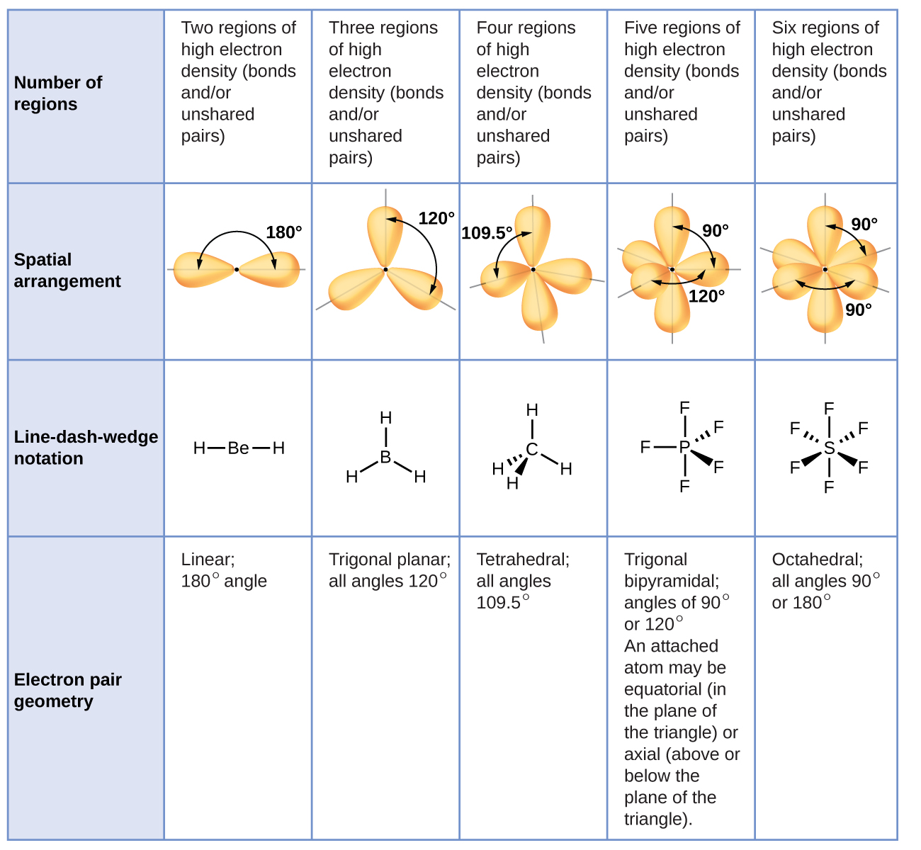
(Figure) illustrates this and other electron-pair geometries that minimize the repulsions among regions of high electron density (bonds and/or lone pairs). Two regions of electron density around a central atom in a molecule form a linear geometry; three regions form a trigonal planar geometry; four regions form a tetrahedral geometry; five regions form a trigonal bipyramidal geometry; and six regions form an octahedral geometry.
Electron-pair Geometry versus Molecular Geometry
It is important to note that electron-pair geometry around a central atom is not the same thing as its molecular geometry. The electron-pair geometries shown in (Figure) describe all regions where electrons are located, bonds as well as lone pairs. Molecular geometry describes the location of the atoms, not the electrons.
We differentiate between these two situations by naming the geometry that includes all electron pairs the electron-pair geometry. The geometry that includes only the placement of the atoms in the molecule is called the molecular geometry. The electron-pair geometries will be the same as the molecular geometries when there are no lone electron pairs around the central atom, but they will be different when there are lone pairs present on the central atom.
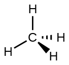
For example, the methane molecule, CH4, which is the major component of natural gas, has four bonding pairs of electrons around the central carbon atom; the electron-pair geometry is tetrahedral, as is the molecular geometry((Figure)). On the other hand, the ammonia molecule, NH3, also has four electron pairs associated with the nitrogen atom, and thus has a tetrahedral electron-pair geometry. One of these regions, however, is a lone pair, and this lone pair influences the molecular geometry of the molecule ((Figure)).
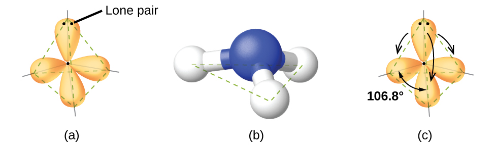
As seen in (Figure), small distortions from the ideal angles in (Figure) can result from differences in repulsion between various regions of electron density. VSEPR theory predicts these distortions by postulating that lone pairs take up more room than bonding pairs. (This is because a bonding is simultaneously pulled toward two different atoms.)
In the ammonia molecule, the three hydrogen atoms attached to the central nitrogen are not arranged in a flat, trigonal planar molecular structure, but rather in a three-dimensional trigonal pyramid ((Figure)) with the nitrogen atom at the apex and the three hydrogen atoms forming the base. The ideal bond angles in a trigonal pyramid are based on the tetrahedral electron-pair geometry. Again, there are slight deviations from the ideal because lone pairs occupy larger regions of space than do bonding electrons. The H–N–H bond angles in NH3 are slightly smaller than the 109.5° angle in a regular tetrahedron ((Figure)) because the lone pair takes up more space than the bonding pairs. (Figure) illustrates the ideal molecular structures, which are predicted based on the electron-pair geometries for various combinations of lone pairs and bonding pairs.
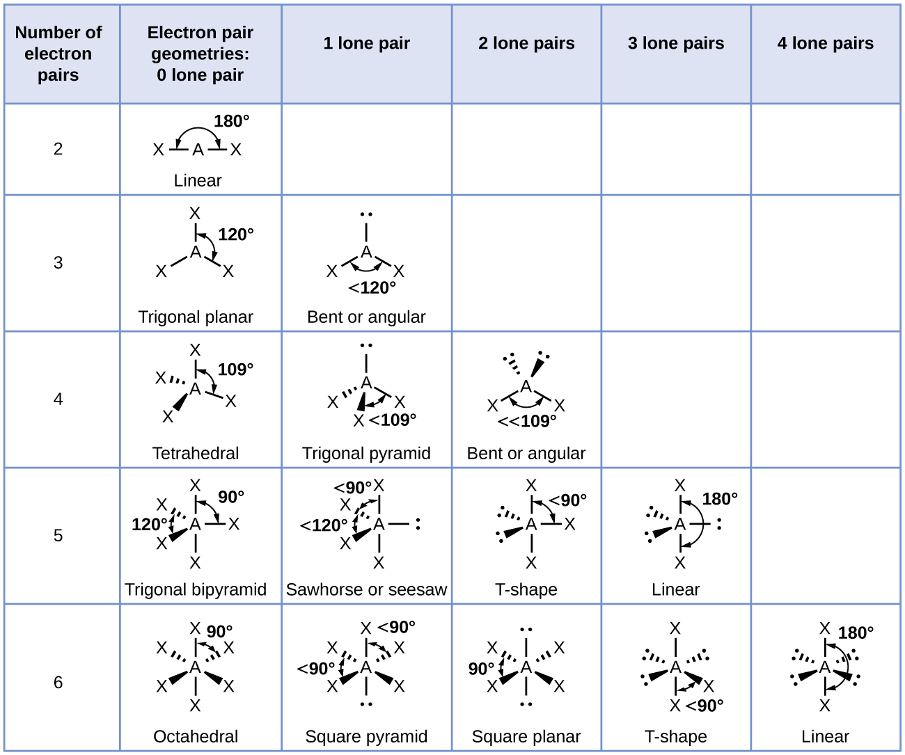
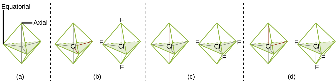
According to VSEPR theory, the terminal atom locations (Xs in (Figure)) are equivalent within the linear, trigonal planar, and tetrahedral electron-pair geometries (the first three rows of the table). It does not matter which X is replaced with a lone pair because the molecules can be rotated to convert positions. For trigonal bipyramidal electron-pair geometries, however, there are two distinct X positions, as shown in (Figure): an axial position (if we hold a model of a trigonal bipyramid by the two axial positions, we have an axis around which we can rotate the model) and an equatorial position (three positions form an equator around the middle of the molecule). As shown in (Figure), the axial position is surrounded by bond angles of 90°, whereas the equatorial position has more space available because of the 120° bond angles. In a trigonal bipyramidal electron-pair geometry, lone pairs always occupy equatorial positions because these more spacious positions can more easily accommodate the larger lone pairs.
Theoretically, we can come up with three possible arrangements for the three bonds and two lone pairs for the ClF3 molecule ((Figure)). The stable structure is the one that puts the lone pairs in equatorial locations, giving a T-shaped molecular structure.
When a central atom has two lone electron pairs and four bonding regions, we have an octahedral electron-pair geometry. The two lone pairs are on opposite sides of the octahedron (180° apart), giving a square planar molecular structure that minimizes lone pair-lone pair repulsions ((Figure)).
Predicting Electron Pair Geometry and Molecular Geometry
The following procedure uses VSEPR theory to determine the electron pair geometries and the molecular geometries:
- Draw the Lewis structure of the molecule or polyatomic ion.
- Count the number of regions of electron density (lone pairs and bonds) around the central atom. A single, double, or triple bond counts as one region of electron density.
- Identify the electron-pair geometry based on the number of regions of electron density: linear, trigonal planar, tetrahedral, trigonal bipyramidal, or octahedral ((Figure), first column).
- Use the number of lone pairs to determine the molecular structure ((Figure)).
The following examples illustrate the use of VSEPR theory to predict the molecular geometry of molecules or ions that have no lone pairs of electrons. In this case, the molecular geometry is identical to the electron pair geometry.
Predicting Electron-pair Geometry and Molecular Structure: CO2 and BCl3
Predict the electron-pair geometry and molecular geometry for each of the following:
(a) carbon dioxide, CO2, a molecule produced by the combustion of fossil fuels
(b) boron trichloride, BCl3, an important industrial chemical
Solution:
(a) We write the Lewis structure of CO2 as:
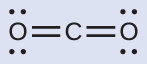
This shows us two regions of high electron density around the carbon atom—each double bond counts as one region, and there are no lone pairs on the carbon atom. Using VSEPR theory, we predict that the two regions of electron density arrange themselves on opposite sides of the central atom with a bond angle of 180°. The electron-pair geometry and molecular geometry are identical, and CO2 molecules are linear.
(b) We write the Lewis structure of BCl3 as:
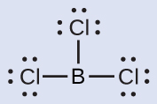
Thus we see that BCl3 contains three bonds, and there are no lone pairs of electrons on boron. The arrangement of three regions of high electron density gives a trigonal planar electron-pair geometry. The B–Cl bonds lie in a plane with 120° angles between them. BCl3 also has a trigonal planar molecular geometry.

Check Your Learning:
Carbonate, CO32-, is a common polyatomic ion found in various materials from eggshells to antacids. What are the electron-pair geometry and molecular geometry of this polyatomic ion?

Due to resonance, all three C–O bonds are identical. Whether they are single, double, or an average of the two, each bond counts as one region of electron density. The electron-pair geometry is trigonal planar and the molecular geometry is trigonal planar.
Predicting Electron-pair Geometry and Molecular Structure: Ammonium
Two of the top 50 chemicals produced in the United States, ammonium nitrate and ammonium sulfate, both used as fertilizers, contain the ammonium ion. Predict the electron-pair geometry and molecular structure of the NH4+ cation.
Solution:
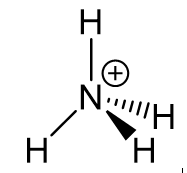
We write the Lewis structure of NH4+ as:

We can see that NH4+ contains four bonds from the nitrogen atom to hydrogen atoms and no lone pairs. We expect the four regions of high electron density to arrange themselves so that they point to the corners of a tetrahedron with the central nitrogen atom in the middle ((Figure)). Therefore, the electron pair geometry of NH4+ is tetrahedral, and the molecular geometry is also tetrahedral.
Check Your Learning:
Identify a molecule with trigonal bipyramidal molecular geometry.
Any molecule with five electron pairs around the central atoms including no lone pairs will be trigonal bipyramidal. PF5 is a common example.
The next several examples illustrate the effect of lone pairs of electrons on molecular geometry.
Predicting Electron-pair Geometry and Molecular Structure: Lone Pairs on the Central Atom
Predict the electron-pair geometry and molecular geometry of a water molecule.
Solution:
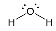
The Lewis structure of H2O indicates that there are four regions of high electron density around the oxygen atom: two lone pairs and two chemical bonds:
We predict that these four regions are arranged in a tetrahedral fashion, as indicated in (Figure). Thus, the electron-pair geometry is tetrahedral and the molecular geometry is bent with an angle slightly less than 109.5°. (In fact, the bond angle is 104.5°.)
Check Your Learning:
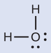
The hydronium ion, H3O+, forms when acids are dissolved in water. Predict the electron-pair geometry and molecular geometry of this cation.
electron pair geometry: tetrahedral; molecular geometry: trigonal pyramidal
Predicting Electron-pair Geometry and Molecular Structure: SF4
Sulfur tetrafluoride, SF4, is extremely valuable for the preparation of fluorine-containing compounds used as herbicides (i.e., SF4 is used as a fluorinating agent). Predict the electron-pair geometry and molecular geometry of a SF4 molecule.
Solution:
The Lewis structure of SF4 indicates five regions of electron density around the sulfur atom: one lone pair and four bonding pairs:

We expect these five regions to adopt a trigonal bipyramidal electron-pair geometry. To minimize lone pair repulsions, the lone pair occupies one of the equatorial positions. The molecular geometry is seesaw.

Check Your Learning:
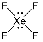
Predict the electron pair geometry and molecular geometry for molecules of XeF2.
The electron-pair geometry is trigonal bipyramidal. The molecular geometry is linear.
Predicting Electron-pair Geometry and Molecular Geometry: XeF4
Of all the noble gases, xenon is the most reactive, frequently reacting with elements such as oxygen and fluorine. Predict the electron-pair geometry and molecular geometry of the XeF4 molecule.
Solution:
The Lewis structure of XeF4 indicates six regions of high electron density around the xenon atom: two lone pairs and four bonds:
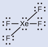
These six regions adopt an octahedral arrangement, which is the electron-pair geometry. To minimize repulsions, the lone pairs should be on opposite sides of the central atom. The five atoms are all in the same plane and have a square planar molecular geometry.
Check Your Learning:
In a certain molecule, the central atom has three lone pairs and two bonds. What will the electron pair geometry and molecular geometry be?
electron pair geometry: trigonal bipyramidal; molecular geometry: linear
Molecular Geometry for Multicenter Molecules
When a molecule or polyatomic ion has only one central atom, the molecular geometry completely describes the shape of the molecule. Larger molecules do not have a single central atom, but are connected by a chain of interior atoms that each possess a “local” geometry. The way these local geometries are oriented with respect to each other also influences the molecular shape, but such considerations are largely beyond the scope of this introductory discussion. For our purposes, we will only focus on determining the local geometries.
Predicting Structure in Multicenter Molecules:
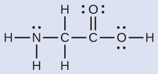
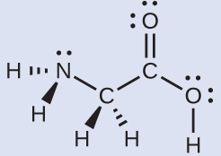
The Lewis structure for the simplest amino acid, glycine, H2NCH2CO2H, is shown here. Predict the local geometry for the nitrogen atom, the two carbon atoms, and the oxygen atom with a hydrogen atom attached:
Solution:
Consider each central atom independently. The electron-pair geometries:
- nitrogen––four regions of electron density; tetrahedral
- carbon (CH2)––four regions of electron density; tetrahedral
- carbon (CO2)—three regions of electron density; trigonal planar
- oxygen (OH)—four regions of electron density; tetrahedral
The local geometries:
- nitrogen––three bonds, one lone pair; trigonal pyramidal
- carbon (CH2)—four bonds, no lone pairs; tetrahedral
- carbon (CO2)—three bonds (double bond counts as one region of electron density), no lone pairs; trigonal planar
- oxygen (OH)—two bonds, two lone pairs; bent
Check Your Learning:
Another amino acid is alanine, which has the Lewis structure shown here. Predict the electron-pair geometry and local geometry of the nitrogen atom, the three carbon atoms, and the oxygen atom with hydrogen attached:
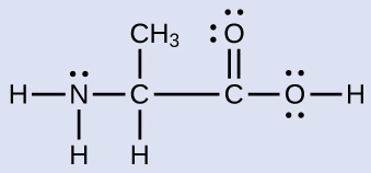
electron-pair geometries: nitrogen––tetrahedral; carbon (CH)—tetrahedral; carbon (CH3)—tetrahedral; carbon (CO2)—trigonal planar; oxygen (OH)—tetrahedral; local geometries: nitrogen—trigonal pyramidal; carbon (CH)—tetrahedral; carbon (CH3)—tetrahedral; carbon (CO2)—trigonal planar; oxygen (OH)—bent
The molecular shape simulator lets you build various molecules and practice naming their electron-pair geometries and molecular structures.
Molecular Polarity and Dipole Moment
As discussed previously, polar covalent bonds connect two atoms with differing electronegativities, leaving one atom with a partial positive charge (δ+) and the other atom with a partial negative charge (δ–), as the electrons are pulled toward the more electronegative atom. This separation of charge gives rise to a bond dipole moment.
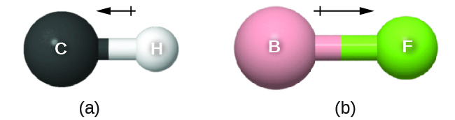
This bond dipole moment can be represented as a vector, a quantity having both direction and magnitude ((Figure)). Dipole vectors are shown as arrows pointing along the bond from the less electronegative atom toward the more electronegative atom. A small plus sign is drawn on the less electronegative end to indicate the partially positive end of the bond. The length of the arrow is proportional to the magnitude of the electronegativity difference between the two atoms.
A whole molecule may also have a separation of charge, depending on its molecular structure and the polarity of each of its bonds. If such a charge separation exists, the molecule is said to be a polar molecule (or dipole); otherwise the molecule is said to be nonpolar. The dipole moment measures the extent of net charge separation in the molecule as a whole. We determine the dipole moment by adding the bond moments in three-dimensional space, taking into account the molecular shape.
For diatomic molecules, there is only one bond, so its bond dipole moment determines the molecular polarity. Homonuclear diatomic molecules such as Br2 and N2 have no difference in electronegativity, so their dipole moment is zero. For heteronuclear molecules such as CO, there is a small dipole moment. For HF, there is a larger dipole moment because there is a larger difference in electronegativity.
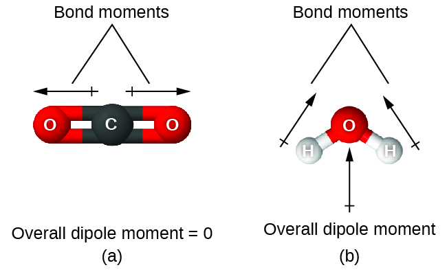
When a molecule contains more than one bond, the geometry must be taken into account. If the bonds in a molecule are arranged such that their bond dipole moments cancel (vector sum equals zero), then the molecule is nonpolar. This is the situation in CO2 ((Figure)). Each of the bonds is polar, but the molecule as a whole is nonpolar. From the Lewis structure, and using VSEPR theory, we determine that the CO2 molecule is linear with polar C=O bonds on opposite sides of the carbon atom. The bond dipole moments cancel because they are pointed in opposite directions. In the case of the water molecule ((Figure)), the Lewis structure again shows that there are two bonds to a central atom, and the electronegativity difference again shows that each of these bonds has a nonzero bond dipole moment. In this case, however, the molecular structure is bent because of the lone pairs on O, and the two bond moments do not cancel. Therefore, water does have a net dipole moment and is a polar molecule (dipole).
The OCS molecule has a structure similar to CO2, but a sulfur atom has replaced one of the oxygen atoms. To determine if this molecule is polar, we draw the molecular structure. VSEPR theory predicts a linear molecule:
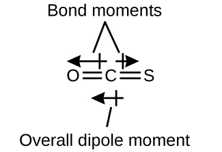
The C-O bond is considerably polar. Although C and S have very similar electronegativity values, S is slightly more electronegative than C, and so the C-S bond is just slightly polar. Because oxygen is more electronegative than sulfur, the oxygen end of the molecule is the negative end.
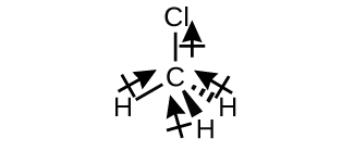
Chloromethane, CH3Cl, is a tetrahedral molecule with three slightly polar C-H bonds and a more polar C-Cl bond. The relative electronegativities of the bonded atoms is H < C < Cl, and so the bond moments all point toward the Cl end of the molecule and sum to yield a considerable dipole moment (the molecules are relatively polar).
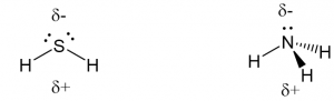
For molecules of high symmetry such as BF3 (trigonal planar), CH4 (tetrahedral), PF5 (trigonal bipymidal), and SF6 (octahedral), all the bonds are of identical polarity (same bond moment) and they are oriented in geometries that yield nonpolar molecules (dipole moment is zero). Molecules of less geometric symmetry, however, may be polar even when all bond moments are identical. For these molecules, the directions of the equal bond moments are such that they sum to give a nonzero dipole moment and a polar molecule. Examples of such molecules include hydrogen sulfide, H2S (nonlinear), and ammonia, NH3 (trigonal pyramidal).
To summarize, to be polar, a molecule must:
- Contain at least one polar covalent bond.
- Have a molecular structure such that the sum of the vectors of each bond dipole moment does not cancel.
Properties of Polar Molecules
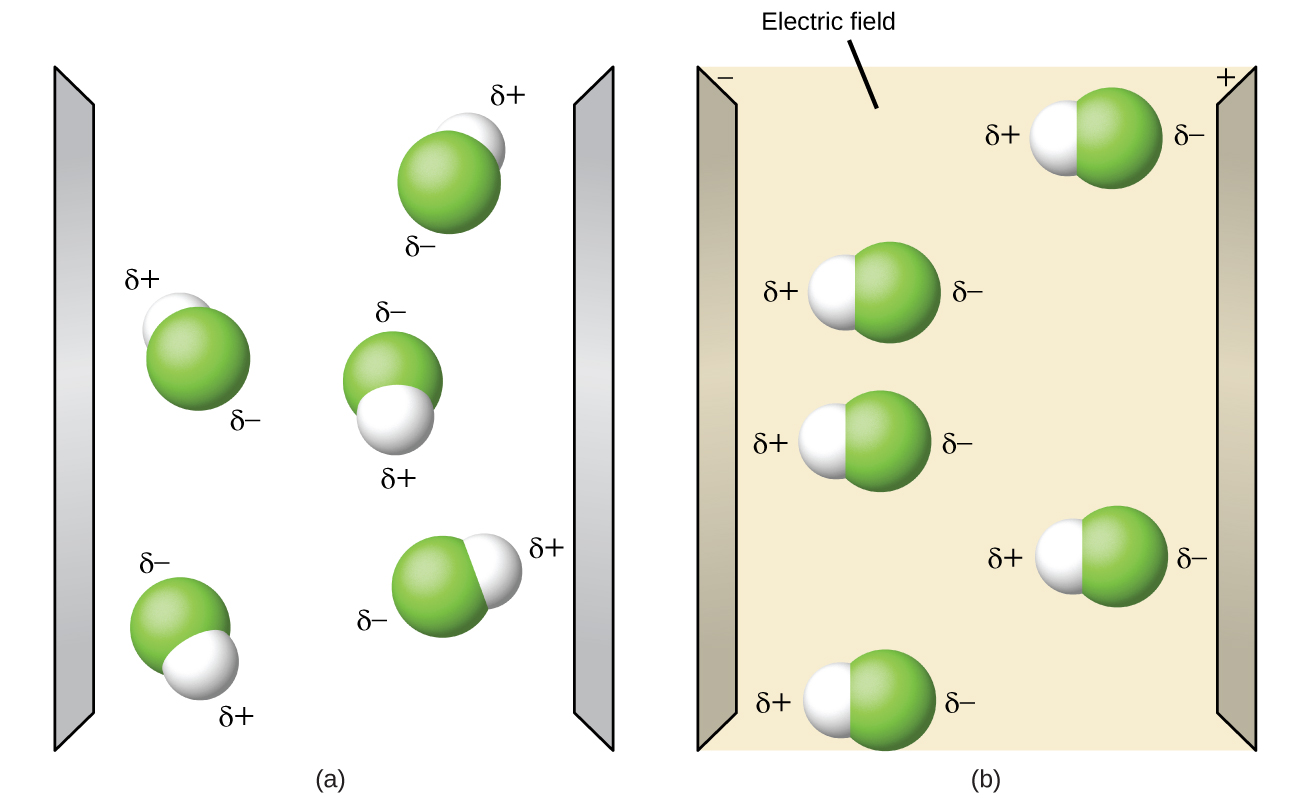
Polar molecules tend to align when placed in an electric field with the positive end of the molecule oriented toward the negative plate and the negative end toward the positive plate ((Figure)). We can use an electrically charged object to attract polar molecules, but nonpolar molecules are not attracted. Also, polar solvents are better at dissolving polar substances, and nonpolar solvents are better at dissolving nonpolar substances.
The molecule polarity simulation provides many ways to explore dipole moments of bonds and molecules.
Key Concepts and Summary
VSEPR theory predicts the three-dimensional arrangement of atoms in a molecule. It states that valence electrons will assume an electron-pair geometry that minimizes repulsions between areas of high electron density (bonds and/or lone pairs). Molecular geometry, which refers only to the placement of atoms in a molecule and not the electrons, is equivalent to electron-pair geometry only when there are no lone electron pairs around the central atom. A dipole moment measures a separation of charge. For one bond, the bond dipole moment is determined by the difference in electronegativity between the two atoms. For a molecule, the overall dipole moment is determined by both the individual bond moments and how these dipoles are arranged in the molecular structure. Polar molecules (those with an appreciable dipole moment) interact with electric fields, whereas nonpolar molecules do not.
Glossary
- axial position
- location in a trigonal bipyramidal geometry in which there is another atom at a 180° angle and the equatorial positions are at a 90° angle
- bond dipole moment
- separation of charge in a bond that depends on the difference in electronegativity and the bond distance represented by partial charges or a vector
- dipole moment
- property of a molecule that describes the separation of charge determined by the sum of the individual bond moments based on the molecular structure
- electron-pair geometry
- arrangement around a central atom of all regions of electron density (bonds, lone pairs, or unpaired electrons)
- equatorial position
- one of the three positions in a trigonal bipyramidal geometry with 120° angles between them; the axial positions are located at a 90° angle
- linear
- shape in which two outside groups are placed on opposite sides of a central atom
- molecular geometry
- geometry that includes only the placement of the atoms in the molecule
- octahedral
- shape in which six outside groups are placed around a central atom such that a three-dimensional shape is generated with four groups forming a square and the other two forming the apex of two pyramids, one above and one below the square plane
- polar molecule
- (also, dipole) molecule with an overall dipole moment
- tetrahedral
- shape in which four outside groups are placed around a central atom such that a three-dimensional shape is generated with four corners and 109.5° angles between each pair and the central atom
- trigonal bipyramidal
- shape in which five outside groups are placed around a central atom such that three form a flat triangle with 120° angles between each pair and the central atom, and the other two form the apex of two pyramids, one above and one below the triangular plane
- trigonal planar
- shape in which three outside groups are placed in a flat triangle around a central atom with 120° angles between each pair and the central atom
- valence shell electron-pair repulsion theory (VSEPR)
- theory used to predict the bond angles in a molecule based on positioning regions of high electron density as far apart as possible to minimize electrostatic repulsion
