Support and Movement
Unit 14: Biomechanics
Learning Objectives
At the end of this unit, you should be able to:
I. Describe how muscles attach to bones to produce movement.
II. Describe the principle of muscular antagonism in movement, using the forearm as an example.
III. Define the following terms: lever, fulcrum, resistance, effort.
IV. Describe three types of levers and give an example of each type in the human body.
V. Explain the biomechanical principles and functioning of a lever system.
Learning Objectives and Guiding Questions
At the end of this unit, you should be able to complete all the following tasks, including answering the guiding questions associated with each task.
I. Describe how muscles attach to bones to produce movement.
- Use one complete sentence to describe the function of a tendon (See Unit 6).
- State the specific tissue type of which tendons are composed (See Unit 6).
- Describe the location of and relationship between the origin and the insertion of a muscle, to explain how muscles move bones.
II. Describe the principle of muscular antagonism in movement, using the forearm as an example.
- Define the terms ‘agonist’ and ‘antagonist’ as they pertain to specific movements and muscles.
- Using the elbow joint as a specific example, explain how antagonistic pairs of muscles produce a movement about a joint.
III. Define the following terms: lever, fulcrum, resistance, effort.
- Draw an annotated diagram of a lever system. Your diagram should show where along a lever each major component acts, along with single-sentence definitions for each of these terms:
- Lever
- Fulcrum
- Resistance
- Effort
IV. Describe three types of levers and give an example of each type in the human body.
- Draw annotated diagrams of each of the three classes of levers, showing the major components of a lever system as well as the location where the effort and resistance are applied. Provide one specific example of each class of lever found in the human body.
- Draw an annotated diagram of each of the following movements, describing each as a lever system. Each diagram should include labels identifying the main components (bone, muscle, joint, force), both as part of a lever system (using the terms lever, fulcrum, resistance, effort) and by their correct anatomical name (for bones and muscles).
- Bending the elbow (flexion at the elbow).
- Starting with the head tilted forward, tilt the head upwards (extension of the head).
- Standing on your toes (extension at the ankle).
- Clearly indicate the following on each diagram from the question above:
- The exact location where the resistance is applied to the lever
- The exact location where the effort is applied to the lever
- The resistance arm
- The effort arm
- Draw annotated diagrams to demonstrate whether each of the three classes of levers can be a power lever, a speed lever, both, or neither.
V. Explain the biomechanical principles and functioning of a lever system.
- Using the flexion of the forearm as an example, explain how a lever system is used to move body parts or maintain the posture of body parts.
- Describe one disadvantage and two advantages of the insertion of the biceps brachii being near the elbow joint:
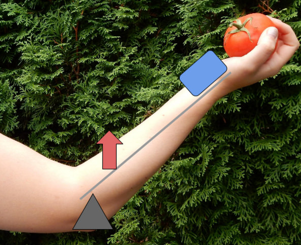
- Draw a straight horizontal line representing a forearm (length = 35 cm). This line shows the distance from the elbow joint to a weight held in the hand (resistance arm). Draw an arrow at one end of the line representing the elbow joint, and a square at the opposite end of the line representing the weight to be lifted. The weight will be lifted through the actions of the biceps brachii muscle. Assuming the distance between the elbow joint and the insertion point of the biceps brachii is 5 cm, add a circle to your horizontal line to represent the insertion of the biceps brachii muscle onto the radius (effort arm). Note: what matters here is the location of the insertion point of a muscle onto a bone, not the location or orientation of the muscle itself. See Figure 1 for an example of this third-class lever system
- Then, report the following for the lever system described above:
- The length of the resistance arm, in cm
- The length of the effort arm, in cm
- The effort exerted by the biceps brachii, if the resistance is:
- 1 kg
- 10 kg
- 25 kg
- The effort exerted by the biceps brachii to lift a resistance of 10 kg, if the distance between the elbow joint and the insertion point of the biceps brachii remains the same (5 cm), but the total length of the forearm is:
- 25 cm
- 35 cm
- 50 cm
- The effort exerted by the biceps brachii to lift a resistance of 10 kg, if the total length of the forearm remains the same (35 cm) but the distance between the elbow joint and the insertion point of the biceps brachii is:
- 1 cm
- 5 cm
- 7 cm
- 28 cm
- Using your diagram and your results from the above calculations, explain the following:
- Whether more or less effort is required to move the weight in the hand, when the biceps brachii’s insertion point is relatively close to the elbow vs. further away.
- Whether the weight in the hand moves a greater or lesser distance when the same amount of effort is exerted by the biceps brachii, but the effort arm varies in length.
- Whether the weight in the hand would move faster or slower when the same amount of effort is exerted by the biceps brachii over the same period of time, but the effort arm varies in length.
Part 1: Skeletal Muscle Anatomy
Muscle Attachment to Skeleton
To move the skeleton, the tension created by the contraction of the fibres in most skeletal muscles is transferred to the tendons. The tendons are strong bands of dense, regular connective tissue that connect muscles to bones. The bone connection is why this muscle tissue is called skeletal muscle.
To pull on a bone, that is, to change the angle at its synovial joint, which essentially moves the skeleton, a skeletal muscle must be attached to a fixed part of the skeleton. The moveable end of the muscle which attaches to the bone being pulled is called the muscle’s insertion, whereas the end of the muscle attached to a fixed (stabilized) bone is called the origin.
Muscular Antagonism
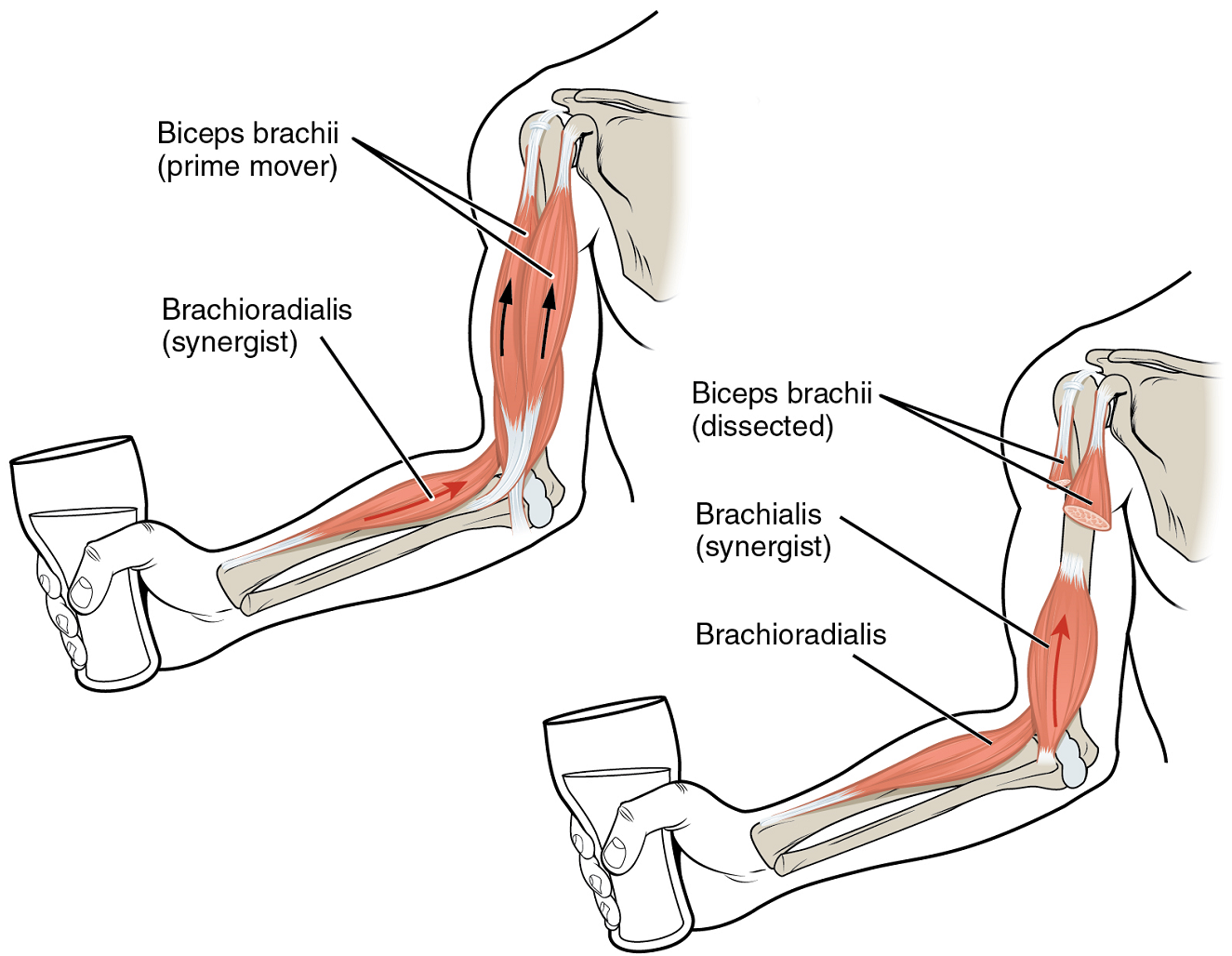
Although a number of muscles may be involved in an action, the principal muscle involved is called the prime mover, or agonist. To lift a cup, a muscle called the biceps brachii is the prime mover; however, because this muscle can be assisted by the brachialis, the brachialis is called a synergist in this action (Figure 1). A synergist can also be a fixator which stabilizes the bone that is the attachment for the prime mover’s origin.
A muscle with the opposite action of the prime mover is called an antagonist. Antagonists play two important roles in muscle function: (1) they maintain body or limb position, such as holding the arm out or standing erect; and (2) they control rapid movement as in shadow boxing without landing a punch, and thereby check the motion of a limb.
For example, to extend the knee, a group of four muscles called the quadriceps femoris in the anterior compartment of the thigh is activated. These muscles would be called the agonists of knee extension. However, to flex the knee, an opposite or antagonistic set of muscles called the hamstrings is activated. Flexing the knee involves the hamstrings muscles as the agonists and the quadriceps femoris muscles as the antagonists. As you can see, the terms agonist and antagonist are associated with a particular movement, and these terms can be reversed for opposing movements. See Table 1 for a list of some common agonists and antagonists.
| Agonist | Antagonist | Movement |
|---|---|---|
| Biceps brachii (in anterior compartment of arm) | Triceps brachii (in posterior compartment of arm) | The biceps brachii flexes the forearm, whereas the triceps brachii extends it |
| Hamstrings (group of three muscles in the posterior compartment of thigh) | Quadriceps femoris (group of four muscles in anterior compartment of thigh) | The hamstrings flex the leg, whereas the quadriceps femoris extend it |
| Flexor digitorum superficialis and flexor digitorum profundus (in anterior compartment of forearm) | Extensor digitorum (in posterior compartment of forearm) | The flexor digitorum superficialis & profundus flex the fingers and hand at the wrist, whereas the extensor digitorum extends the fingers and hand at the wrist |
Muscles without Attachments to the Skeleton
Some skeletal muscles do not pull on the skeleton to cause movements. For example, the muscles that produce facial expressions have their insertions and origins in the skin, and particular muscles contract to form a smile or frown, form sounds or words, or raise the eyebrows. There are also such skeletal muscles in the tongue, as well as in the external urinary and anal sphincters that allow for voluntary regulation of urination and defecation, respectively. Another example is the diaphragm, which contracts and relaxes to change the volume of the pleural cavities without moving the skeleton.
Part 2: Lever Systems
Skeletal muscles do not work by themselves. First, muscles are arranged in pairs based on their functions. Second, most muscles are attached to the bones of the skeleton and the location and nature of the connection determines the force, speed and range of movement of the body part being moved. These characteristics depend on one another and can explain the general organization of the muscular and skeletal systems.
General Characteristics
The skeleton and muscles act together to move the body. Have you ever used the back of a hammer to remove a nail from wood? The handle acts as a lever and the head of the hammer acts as a fulcrum, the fixed point that the force is applied to when you pull back or push down on the handle. The effort applied to this system is the pulling or pushing on the handle to remove the nail, which is the resistance to the movement of the handle in the system. The resistance is also sometimes called the load. Our musculoskeletal system works in a similar manner, with bones being stiff levers and the articular endings of the bones—encased in synovial joints—acting as fulcrums. The resistance would be an object or body part being moved, or any resistance to a movement (e.g. your head when you are lifting it). The effort, or applied force, comes from contracting particular skeletal muscles.
The characteristics and operation of a particular lever system are mainly determined by distances and forces. The two opposing forces are the effort and resistance. There are two main distances to consider: (1) the effort arm, which is the distance from the fulcrum to the insertion point of the skeletal muscle delivering most of the effort, and (2) the resistance arm, which is the distance between the fulcrum and the bulk of the resistance.
In order for movement to occur (e.g. when lifting a weight in your hand), the effort produced by one or several muscles needs to overcome the resistance. When the lever system is balanced, the two opposing forces applied at their respective distances from the fulcrum work to maintain a body posture or carry a particular weight without moving it. Thus, in a balanced lever system, the effort times the effort arm is equal to the resistance times the resistance arm. This is the basic formula used to calculate relationships between forces and distances in a lever system:
Effort x Effort arm = Resistance x Resistance arm
Lever systems that can move heavy loads over short distances using little effort are referred to as “power levers”. Conversely, lever systems that can quickly move light loads over large distances using a large amount of effort are referred to as “speed levers”.
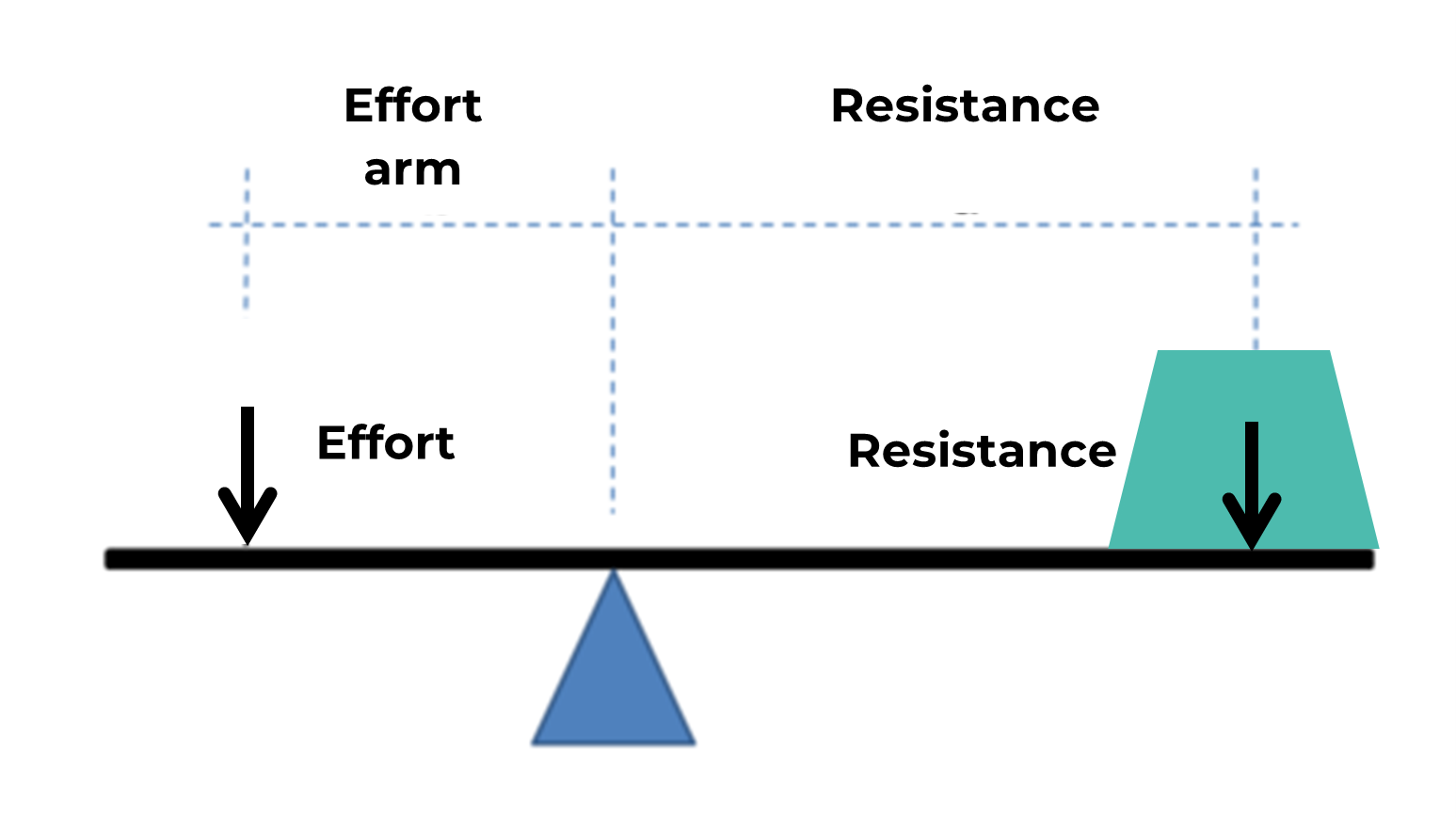
The relative locations of the joint, the load being moved and the insertion point of a muscle (or muscles) delivering the effort determines whether a lever system operates as a power lever or speed lever. For example, a lever system with a muscle insertion point close to the joint (shorter effort arm) and a resistance far away from the joint (longer resistance arm) will move a particular object relatively fast over a large distance with a great range of motion. However, the muscle(s) involved need(s) to deliver a large effort for the movement to occur (Figure 2).
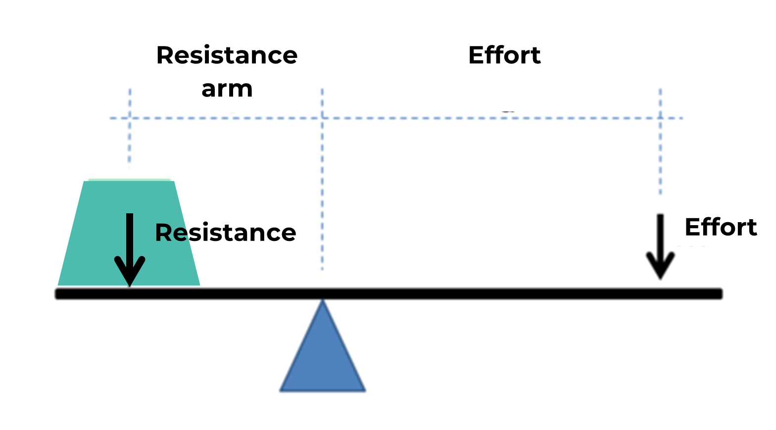
Another lever system with a resistance close to the joint (shorter resistance arm) which is supported by a muscle (or muscles) inserting far away from the joint (longer effort arm) will require a small effort to support or move the resistance. However, the resistance will only be moved over a short distance and slowly (Figure 3).
It is useful to investigate these advantages and disadvantages mathematically. If we begin with the equation stated above, we can solve for the variable “Effort”. This will allow us to calculate the amount of force that is required to maintain a resistance of a specific weight under scenarios with differing effort arm and resistance arm lengths.
[latex]Effort=Resistance\ x\ \frac{Resistance\ arm}{Effort\ arm}[/latex]
As is shown in this equation, if the resistance arm is shorter than the effort arm, then that ratio will be less than one. This means that for each unit of resistance on the lever, less than one unit of effort is required to support that weight. This is characteristic of a power lever. If the resistance arm is longer than the effort arm, then that ratio will be greater than one. This means that for each unit of resistance on the lever, more than one unit of effort is required to support that weight. This is characteristic of a speed lever.
A similar equation may be used to investigate the relationship between the distance (or speed) moved by the effort (that is, the degree or speed of muscle contraction) and the distance (or speed) moved by the resistance.
[latex]Distance\ moved\ by\ resistance\ =Distance\ moved\ by\ effort\ x\ \frac{Resistance\ arm}{Effort\ arm}[/latex]
[latex]Speed\ of\ resistance\ =Speed\ of\ effort\ x\ \frac{Resistance\ arm}{Effort\ arm}[/latex]
Again, the same ratio of the lengths of resistance arm to the effort arm is used. If the resistance arm is longer than the effort arm, then the ratio will be greater than one. For every centimeter moved by the effort (degree of muscle contraction), the resistance will move by more than one centimeter. For every centimeter per second moved by the effort (speed of muscle contraction), the resistance will move at more than one centimeter per second. This is characteristic of a speed lever.
If the resistance arm is shorter than the effort arm, then the ratio will be less than one. For every centimeter moved by the effort (degree of muscle contraction), the resistance will move by less than one centimeter. For every centimeter per second moved by the effort (speed of muscle contraction), the resistance will move at less than one centimeter per second. This is characteristic of a power lever.
There are several types of lever systems in the body, identified as either first-class, second-class or third-class levers.
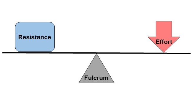
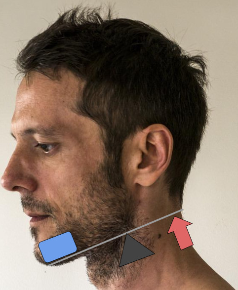
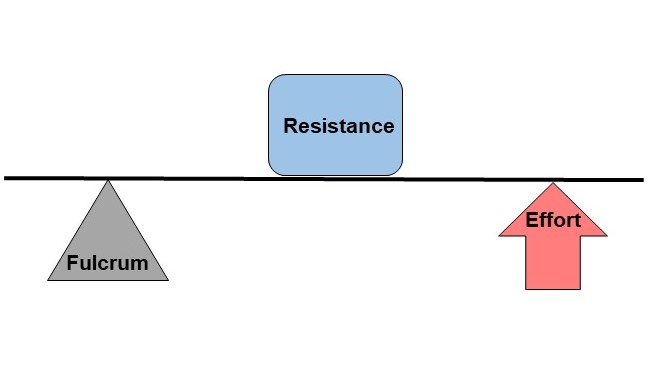
First-class levers
First-class levers are the simplest types of lever, where the two forces, the effort and the resistance, are applied on opposite sides of the fulcrum (Figures 4). In the body, the best example of a first-class lever is the way your head is raised off your chest (Figure 5). The posterior neck muscles produce the effort, the facial skeleton is the resistance, and the atlanto-occipital joint behaves as the fulcrum.
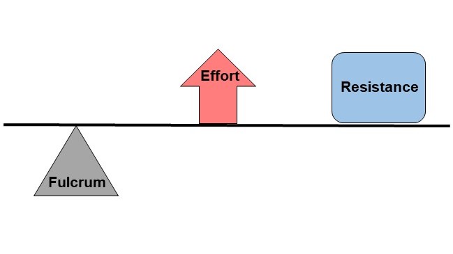
Second-class levers
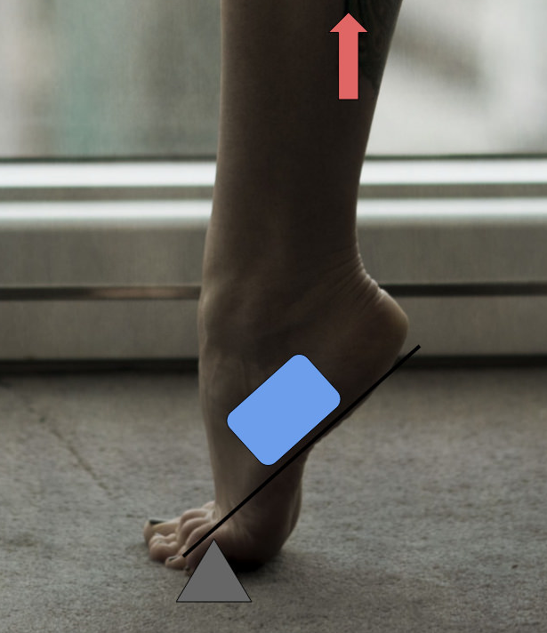
Second-class levers have the resistance between the effort and the fulcrum (Figure 6). The effort is closer to the resistance than the fulcrum, which allows a large resistance to be moved by a small amount of effort. However, this means that the resistance will be moved at a relatively slow pace, and can only be moved a short distance. Any time you stand up on your toes, as shown in Figure 7, you are using a second-class lever.
The weight of your body acts as the resistance, your calf muscles produce the effort, and the joints in the balls of your feet (metatarsophalangeal joints) act as fulcrums. Second-class levers are always power levers because the effort arm is always longer than the resistance arm. This is a consequence of the resistance lying between the fulcrum and effort.
Third-class levers
Third-class levers are the most common type of levers in your body (Figure 8). The effort is applied between the fulcrum and the resistance, which allows the resistance to be moved relatively quickly over large distances. When you lift your hand by flexing your biceps brachii, you are using a third-class lever. The elbow joint acts as the fulcrum, the biceps brachii produces the effort, and the weight of your hand is the resistance being lifted (Figure 9). Third-class levers are always speed levers because the effort arm is always shorter than the resistance arm. This is a consequence of the effort lying between the fulcrum and the resistance.
Practice Questions
Part 1: Skeletal muscle anatomy
Part 2: Lever systems
End of a skeletal muscle that is attached to the structure (usually a bone) that is moved when the muscle contracts.
End of a skeletal muscle that is attached to another structure (usually a bone) in a fixed position.
(Also, prime mover) muscle whose contraction is responsible for producing a particular motion.
Muscle whose contraction helps a prime mover in an action.
Synergist that assists an agonist by preventing or reducing movement at another joint, thereby stabilizing the origin of the agonist.
Muscle that opposes the action of an agonist.
Muscle deep to the gluteus maximus on the lateral surface of the thigh that laterally rotates the femur at the hip.
Three long muscles on the back of the upper leg.
A ring-shaped smooth muscle that can open or close a passage in the body.
Skeletal muscle that separates the thoracic and abdominal cavities and is dome-shaped at rest.
The space between the visceral and parietal pleurae.
The point around which a lever rotates.
The pulling or pushing force applied to a lever; in lever system in the body, the effort is a muscle with force applied at the insertion.
(Also, load) The force opposing the action of a lever; in body systems, the resistance may be the mass of the limb (force of gravity acting on the bone) or a load being lifted or moved.
Distance measured from the fulcrum to the effort (e.g. muscle insertion).
Distance measured from the fulcrum to the resistance (centre of gravity or load being moved).
A lever system that can move a load/resistance with less effort (compared to moving the resistance without a lever system); by definition, the mechanical advantage is greater than one (effort arm > resistance arm).
A lever system that can move a load/resistance with more effort and greater speed (compared to moving the resistance without a lever system); by definition, the mechanical advantage is less than one (effort arm < resistance arm).
A lever system in which the effort and resistance are applied on opposite sides of the fulcrum.
A lever system in which the resistance is between the effort and the fulcrum; as the effort arm is always longer than the resistance arm, these are always power levers.
A lever system in which the effort is between the resistance and the fulcrum; the most common lever type in the bottom, these are always speed levers as the effort arm is always shorter than the resistance arm.
Two-headed muscle that crosses the shoulder and elbow joints to flex the forearm while assisting in supinating it and flexing the arm at the shoulder.
