Main Body
You are the engineer on a Liquefied Natural Gas (LNG) carrier with main steam propulsion. The plant can run on Diesel (MDO), Heavy Fuel (HFO) or Boil Off Gas (BOG).
In this exercise you will learn how to start the main boiler from the “Cold Ship” and preparing the steam plant to “Port Condition”.
From the Initial Condition Scenario download “Cold Plant” condition. Click on Home button and you will get access to Process Directory. Go through the all Mimic Drawings (MD) subsystems and familiarize yourself with available ones. It is highly advisable on each picture to click top right corner button with symbol “?” and read the system description before take any actions.
For the purpose of this exercise we are going to start only one boiler. Referenced page number MD relate to Process Directory picture number.
Starting Sequence Diagram
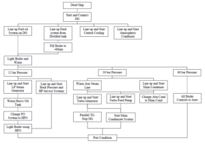
LNG Steam Plant start up Instruction:
Step 1: Start and connect DG
MD 100
- Drain water from MDO service tank till 0.08 m
- Check the MDO fuel outlet valve and supply valve are open
MD 800
- Start Generator #1 and adjust the speed (if necessary)
- Press the “In” push button
- Connect the bus-tie breaker
- Set both DG on “Auto”
Note: All main breakers are equipped with semiautomatic synchronizing logics.
Step 2:
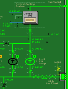
Line up and start Central Cooling System
The central cooling system provide cooling for diesel generators main and turbo generator lube oil cooling, drain cooler.
MD 400
- Open high suction for aux SW pumps.
- Open high sea chest MGPS injection valve.
- Open overboard valve
- Open suction and discharge for Aux SW pump #1 and #2
- Start aux SW pump #1
- Turn “On” Central FW cooling system
- Once pressure and flow comes up set both pumps to “Auto”
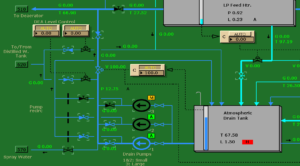
Step 3:
Line up Feed System from the Distilled Tank
MD 620
- Open up Atm drain tank distilled water supply valve
MD 500
- Open shut off valves to/from distilled water tank
- Set DEA Level Control to AUTO
- Open discharge and recirculating valves on the Drain Pumps #1,2
- Start Drain pump #1 and set Drain pump 1 and 2 to AUTO
- Open Atm Drain Tank feed line Shut Off valve
- Set Drain Tank Level Controller to AUTO
- Check that the drain level controller is working. Observe make up from distilled water tank to atmospheric drain tank.
Step 4:
Fill Boiler to -40 mm
MD 510
- Open de-aerator condensate inlet valve
- Open de-aerator main feed-water shutoff valve
- Open de-aerator re-circulation valve
- Open feed water line chemical dosage pump valve
- Start chemical dosage pump
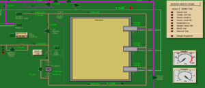
MD 204
- Open boiler filling line valve
- Open steam vent valve
- Open super-heater 1 and 2 drain valves
- Open desuperheater drain valve
- Check and make sure bottom and top blow off valves are closed
- Open internal desuperheater shut off valve
- Open desuperheater control valve to 100% (keep on local control)
- Open boiler feed-water control valve to 30%
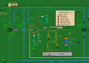
MD 520
- Open suction and discharge valves for electric driven feed water pump #3
- Open recirculation stop valve and set recirculation control to auto
- Start feed pump #3
MD 204
- Observe the water flow
- Fill boiler to -40 mm and set feed water control to “0”
Step 5:
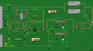
Line Up Fuel System on Diesel Oil
MD 100
- Ensure HFO settling tank outlet and return valves are closed
- Open DO service tank outlet and supply valve to boiler
- Open FO supply suction filter 1, suction and discharge valve of FO supply pump 1, FO heater 1, inlet/outlet valves, FO supply final filter 1
- Open HFO settling tank return shut off valve
- Open FO gas separator recirculating return valve
- Set fuel pressure controller to AUTO
MD 200
- Set FO flow control valve to 30%
MD 100
- Start FO pump #1
- Observe fuel flow
- Check fuel viscosity
- Once viscosity has fallen bellow 100 SST open FO gas separator boiler return valve
- Close HFO settling tank return shut off valve
Step 6:
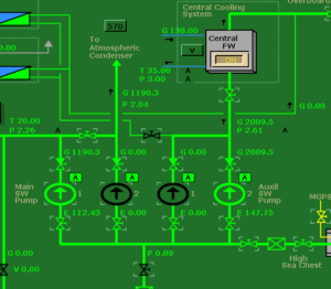
Line Up and Start Atmospheric Condenser
MD 570
- Open Atm condenser SW overboard valve
- Open Atm condenser outlet valve
- Open Atm condenser inlet valve
- Open Atm condenser starting vent valve
- Open Atm condenser condensate shut off valve
MD 500
- Open Atm drain tank condensate return valve
MD 400
- Open main SW pumps 1 and 2 suction and discharge valve
- Open SW crossover valve
- Start SW pump #1, set both pumps to “AUTO”
- Observe water flow and pressure
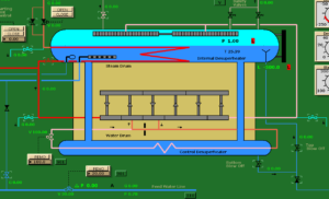
Step 7:
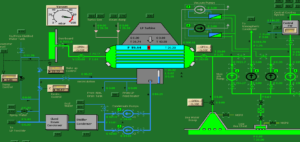
Light On Boiler and Warm
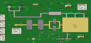
MD 204
- Check the water level in the steam drum
- Make sure the all drain and vent valves are open
- Open starting vent shut off valve
- Open starting vent valve to 100%
Note: The super-heater is protected by the starting valve to maintain a flow of cooling steam to pass through the tubes during lighting up, securing and standby periods. The vent must be open while the boiler is being fired and there is no normal steam flow. If at any time super-heater overheats, the vent valve must be opened immediately. The valves in the super-heater vent line should be opened fully until a pressure of at least 7 bar has been reached. It can be throttled after.
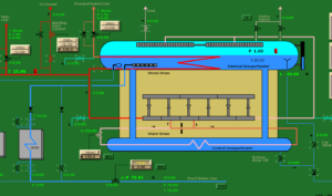
- Open economizer inlet and outlet valves
- Open economizer vent and drain valves
- Close the boiler filling line valve
- Change feed-water control valve for REMOTE
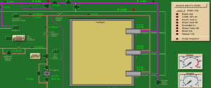
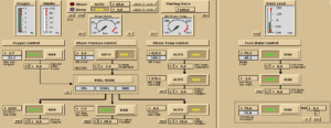
MD 901
- Set Oxygen Control to AUTO
- Set Air Flow Control to AUTO
- Set Fuel Flow Control to AUTO
- Set Water Level Control to AUTO
- Set Water Feed Flow Control to AUTO
- Set Feed-water Pressure Control to AUTO
MD 202
- Start combustion air fan 1
- Set damper control to REMOTE
- Start sealing air fan and open valves to boiler casing and burner
- Set secondary air damper to AUTO
MD 201
- Open atomizing air shut off valve
MD 200
- Open suction and discharge valve for fuel oil meter
- Reset boiler trip
- Observe FO trip valve will open and bypass valve will shut
- Change over FO control valve to REMOTE
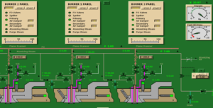
MD 201
- Open burner flow adjust valves to 100% on all burners
- Open the primary and secondary air dampers
MD 902
- Start Boiler Air Purge. The timer should count to “0” and Purge Complete light will come on
MD 201
- Close primary and secondary registers
- Ignite burner 1 by pressing Start button
- Watch the flame indicator. Check smoke indicator
MD 901
- Increase the Master Controller energy command from 0% (min) to 5%
- Check smoke/oxygen content
- See fuel flow going from 196 kg/h to 436 kg/h
MD 204
- Check drum water temperature
- Confirm drain/steam flow escaping from super-heater drain valves when boiler pressure is above atmospheric pressure
- When steam pressure is up to 1.2 bar, close drum air vent valve, super-heater 1 and 2 drain valves and desuperheater drain valve
Step 8:
Line Up and Start LP Steam Generator
MD 620
- Open the Distilled Tank Outlet to L.P. Steam Generator
MD 600
- Open suction and discharge valves for LP steam generator feed water pump 1 and 2
- Open LP steam generator drain cooler feed-water inlet and outlet valves
- Open LP steam generator secondary steam vent valve
- Set the LP steam generator feed water controller output to 100%
- Start LP steam generator feed water pump 1
- Fill the LP steam generator to the normal level “0”
- Set the level control to AUTO
- Set LP steam generator feed water pump 1 and 2 to AUTO
MD 901
When steam pressure in the boiler steam drum reach 3 bar increase firing rate/energy command on Master Controller from 5% to 10% (675 kg/h)
MD 204
- Open desuperheated line bypass valve
MD 560
- Open boiler 1 desuperheated line branch bypass valve
- Open desuperheated steam LP steam generator supply valve
- Open desuperheated steam to Back Pressure system
MD 600
- Set LP steam generator make-up controller manual output to 5%
- Set LP steam generator pressure controller manual out-put to 10%
- Open LP steam generator primary steam shutoff valve
- Open LP steam generator primary steam vent valve
MD 204
- Open desuperheated line supply valve
- Close desuperheated line bypass valve
Note: When steam pressure in the boiler steam drum reach 7 bar, throttle the starting vent valve to 20%
MD 560
- Open Boiler 1 desuperheated line branch valve
- Close Boiler 1 desuperheated line bypass valve
MD 600
- Set LP steam generator make up controller output to 20%
- Set LP generator pressure controller to AUTO
- Close LP steam generator primary steam vent valve
- Open LP steam generator primary steam drain shutoff valve
- Set LP steam generator primary steam drain controller to AUTO
MD 510
- Open drain shutoff valve from LP steam generator to Deaerator
MD 600
- After configuring the secondary steam generating close the secondary steam vent valve
- Gradually open the primary heating steam control valve until the down steam pressure reaches up to 10 bar
- Set up LP steam generator make up steam control valve to AUTO
- Open LP steam generator main shutoff valve
- Open LP steam supply valve to HFO heater
- Open return drain cooler water shutoff valve
Step 9:
Line up and start Back Pressure and HP Service System
MD 550
- Open BP line drain valve
- Open BP make up shut off valves 1 and 2
- Set BP make up controller to AUTO
- Open HP service line shutoff valve
- Set HP service line controller to AUTO
- Open HP automazing steam supply valve
- Open sealing/heating supply valve
- Open boiler air heaters supply valve
- Open deaerator heating supply valve
- Open steam dump controller shutoff valve
- Open atmospheric condenser steam dump shutoff valve
- Set steam dump controller to AUTO
- Close BP line drain valve
MD 510
- Open Deaerator heating steam shutoff valve
MD 500
- Open atmospheric drain tank drain return valve
MD 202
- Open air preheater drain valve
- Open air preheater shutoff valve
- Set up combustion temperature controller to AUTO
Step 10:
Warm HFO Tank
MD 100
- Open HFO settling tank steam inlet and drain valve
- As the temperature rises check the tank for water. Drain the water to 0.15 m.
- The temperature normally need to be around 50 C for good pumping conditions
- Open steam tracing shutoff valve
- Open FO heater 1 steam inlet and drain outlet valve
- Set up viscosity controller to AUTO
- Monitor viscosity value fluctuation. Make sure it will stabilize eventually
Step 11:
Warm Auxiliary Steam Line
MD 204
- Open aux line supply valve bypass.
MD 560
- Open aux line branch valve bypass.
- Open aux line drain valve.
Step 12
Line Up and Start Main Condenser
MD 400
- Open main condenser overboard valve
- Open main condenser outlet valve
- Open main condenser inlet valve
- Monitor sea water flow
- Open condensate re-circulation stop valve
- Check the quantity of any condensate already in the main condenser. Initial filling of the main condenser is by direct drop from the distilled water tank through filling valve
MD 620
- Open Main Condenser Distilled water supply valve
MD 400
- Open deaerator make/discharge line stop valve
- Set up Make-up Controller to AUTO
- Set up Re-circulation Controller to AUTO
- Set up Dump Controller to AUTO
MD 630
- Open CC distiller condenser cooling water bypass valve
MD 500
- Open gland condenser bypass feed water valve
- Open LP feed heater feedwater bypass valve
MD 400
- Open condensate pump 1 suction and discharge valves
- Start condensate pump 1. Monitor condensate flow
- Ensure the condenser level control is operating correctly
- Line up the condensate pump 2 and put both pump to AUTO
- Open vacuum cooling water supply valve
- Start main vacuum pump 1 and rise the condenser vacuum
- Set vacuum pumps 1 and 2 to AUTO
- Open sealing water supply valve
Step 13
Change FO System to HFO
MD 201
- On burner 1 control panel press STOP button
- The action of stopping the burner open each burner rail recirculation valve
MD 100
- Open HFO settling tank high suction valve
- Open HFO settling tank return shutoff valve
- Close FO gas separator return valve
- Close DO service tank supply valve
- As the heavier fuel oil purges the system the pressure will rise. If necessary change over pressure controller to manual and adjust controller output to suitable pump back pressure level (13 bar)
- Wait till viscosity stabilize around 35 sCt before light up boiler
Step 14:
Light Boiler Using HFO
MD 200
- On the boiler safety panel press Reset button
- Make sure the Fuel Trip valve is open and Fuel Bypass valve is close
MD 201
- On burner 1, 2, 3 Control Panels open Primary and Secondary Air Dampers
- Close automizing air shut off valve.
- Open automizing steam drain valve.
- Open automizing steam shut off valve.
- Set up automizing stream pressure controller to AUTO.
MD 902
- On the boiler air purge panel press Purge Start button and wait till purging complete light will turn On
MD 201
- On burner 1, 2, 3 Control Panels close Primary and Secondary Air Dampers
- On burner 1 panel press Start button and observe ignition
- Close automizing steam drain valve.
MD 901
- On the Steam Pressure Controller set output from Master Controller to 10%.
MD 100
- Open FO gas separator return valve
- Close HFO settling tank return shutoff valve
Step 15:
Bring the Gland Steam Steam Condenser in to Service
MD 500
- Open gland condenser inlet valve
- Close gland condenser bypass valve
- Start gland condenser fan
- Open gland condenser water loop seal valve
Step 16:
Line Up and Start Turbo Feed Pump
MD 204
- Open aux line supply valve
- Close aux line bypass valve
MD 560
- Open aux line brunch valve
- Close aux line bypass valve
- Close aux line brunch drain valve
MD 520
- Set feed pump speed governor to 6000 rpm in Local
- Line up lube oil system, including cooling
- Open fresh water main suction valve
- Open fresh water pump 1 suction valve
- Open fresh water pump 1 re-circulation valve
- Drain turbine casing
- Drain steam line
- Open gland bleeder valve
- Open steam exhaust valve
- Check and reset trip
- Open steam supply valve
- Start fresh water pump 1
- Observe: auto start of lube oil starting pump, turbine running, feed water pump discharge pressure
- Open fresh water pump discharge valve and observe that pressure is increasing
- Check deaerator inlet valve is open and re-circulation control in AUTO
- Set fresh water pump speed governor to REMOTE
- Stop FW pump 3
MD 204
- Close starting vent control valve
- Set De superheater temperature controller to REMOTE
Step 17:
Change Atmospheric Condenser to Main Condenser
MD 550
- Open main condenser steam dump shut off valve.
- Close atmospheric condenser steam dump shut off valve.
Step 18:
Line Up and Start Turbo Generator
MD 810
- Open lube oil filter 1 isolating valve.
- Open lube oil cooler cooling water inlet and outlet valve.
- Start electrically driven aux lube oil pump. Confirm the oil supply to the bearing and gearing.
- Open steam line drain valve.
- Open casing drain valve.
- Open gland sealing steam shut off valve.
- Open gland extraction valve.
- Open discharge line valve to the main condenser. Make sure the main condenser vacuum is not effected.
- Open supply line bypass line.
- Open supply line main valve.
MD 800
- Reset turbo generator trip.
MD 810
- When ready to start, slowly open emergency stop valve and allow the unit to turn. Increase the rpm very slowly and allow the turbine to warm through. As the revolutions increase, monitor vibration levels.
- At full speed, 8000 rpm, the stop valve should be fully open.
- Shut all drains, insure the main lube oil pump is taken over oil supply and aux pump has cut out. Set the pump to AUTO.
Step 19:
Parallel Turbo Generator Stop Diesel Generator
MD 800
- Switch off auto control of DG 1 and 2.
- Check the frequencies of turbo generator 1 and 2 around 60.1 – 60.2 Hz.
- Connect turbo generator to the main bus.
- Connect turbo generator 2 to the main bus.
- Disconnect DG 1 and 2 from the main bus.
- Set up DG 1 and 2 to AUTO.
Step 20:
Start Main Condensate System
MD 500
- Open LP heater feedwater inlet and outlet valves.
- Close LP heater bypass valve.
- Open LP feed heater air vent valve.
- Open LP feed heater drain return valve.
- Close LP feed heater atmospheric drain return valve.
- Open LP feed heater condenser dump line valve.
- Set LP feed heater level control on AUTO.
- Open atmospheric drain condenser dump valve.
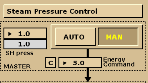
Step 21:
Set Steam Pressure Control to AUTO
MD 901
Steam Plant is ready for Port Condition. Congratulations!
In our next session you will learn how to prepare main propulsion turbine to stand by condition.
