Chapter 3: LPWAN
3.1 Introduction
LPWAN stands for Low-Power Wide-Area Network. This technology provides low-power wide-area coverage which is a requirement for a vast majority of wireless sensor networks. It suits all IoT applications where small amounts of data are transmitted infrequently. Using LPWAN technologies, the IoT devices can also get connected to the Internet directly which eliminates the need for IoT gateways. Therefore, it is a perfect IoT connectivity solution for mobile IoT devices. LPWAN technologies can be divided into two main categories: the ones that use licensed frequency bands and the ones that operate at unlicensed frequencies. LPWAN technologies are more suitable for IoT applications that require long-range connectivity, low power consumption, and near real-time communication.
3.2 Unlicensed band LPWAN
The most important unlicensed cellular technologies are Sigfox and Long Range Radio WAN (LoRaWAN). LoRaWAN is a LPWAN protocol and system architecture developed by LoRa Alliance which provides low-power and long-range communication. LoRa Alliance is an open, non-profit association with many global members from telecommunication companies. LoRa (developed by Semtech) defines the physical layer of the system, which actually is a non-cellular modulation technology for LoRaWAN. Lora supports adaptive data rate by considering a trade off between data rate and range. It uses six spreading factors where the higher spreading factors provide longer range and lower data rate, and the lower spreading factors provide higher data rate at the expense of lower range. LoRaWAN supports both 250 kHz and 125 kHz bandwidth. Depending on the channel bandwidth and the spreading factor, the LoRa data rate varies between 300 bps and 50 kbps.
LoRaWAN defines the protocols over the LoRa physical layer. It is the network architecture which operates in a non-licensed band. The most commonly used frequency bands of LoRaWAN are 433 MHz in Asia, 868 MHz in Europe and 915 MHz in North America. The adaptive data rate provided by LoRa technology will enable optimization of power consumption for different IoT applications. LoRaWAN can provide between 2 to 5 km coverage in rural areas, and around 15 km in urban areas. The maximum data rate of around 100 kbps in both uplink and downlink directions is possible with LoRaWAN in North American deployment. The maximum data rate in Europe is usually lower than North America’s.
Sigfox, the other most widely deployed LPWAN technology, was established in France in 2009 and has deployed networks in many countries since 2012. Sigfox operates in 868 MHz/902 MHz ISM frequency band, and can provide coverage of 30-50 km in rural areas, and 3-10 km in urban areas. The number of devices per access point is as high as one million devices. Due to using ultra narrow spectrum of 100 Hz, the uplink and downlink data rates are very low. The maximum data rate of Sigfox is around 100bps. Even though Sigfox provides bidirectional communication, its downlink capacity is constrained. Mobility is also a drawback for Sigfox, since mobility is difficult to be established using this technology.
3.3 Licenced band LPWAN
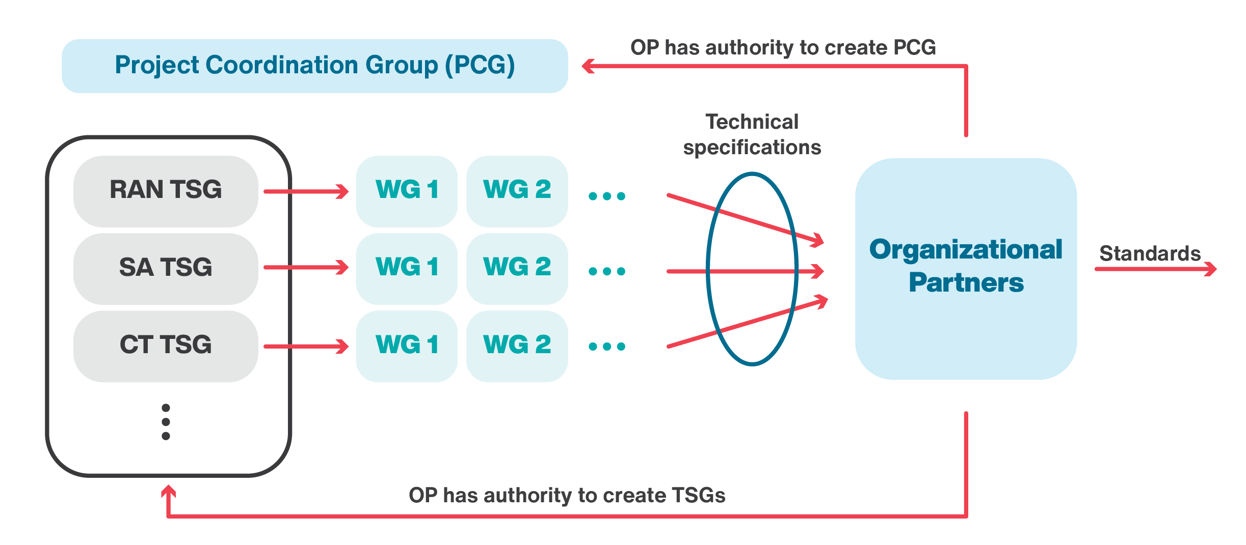
The 3rd Generation Partnership Project is the global technical body which develops technical specifications for mobile communication system. 3GPP was formed in 1998 with the objective to develop new technologies for the third generation of cellular networks. However, it has consequently worked on specifications for the fourth generation and fifth generation of cellular network. 3GPP represents seven regional telecommunications standard development organizations in Europe, America and Asia known as organizational or primary partners. 3GPP writes technical specifications, to be transferred into standards by the organizational partners. The 3GPP organizes its work into different segments. Each segment is represented by a Technical Specification Groups (TSG). Examples of these groups are Radio Access Networks (RAN), Services and Systems Aspects (SA), and Core Network and Terminals. RAN defines the radio communications between the mobile device and the network. SA defines the architecture and services of the network, while CT defines the core network. The project management among these groups is done by the Project Coordination Group (PCG). Each TSG is supported by several Working Groups (WGs). Organizational partners have the authority to create the TSG and PCG groups. Figure 3.1 demonstrates the 3GGP organization.
3GPP has organized its work in terms of release numbers. For example, 4G was first introduced with Release 8 and continues to evolve in higher releases. It should be noted that a specific release number does not belong to a specific generation of mobile network. For example, 3G technologies continued to evolve in Release 8+ in parallel with 4G. Similarly, 3GPP introduced 5G technologies from Release 15+, but will continue to evolve 4G in parallel. Beside broadband communication of voice and data, 3GPP considers Machine to Machine (M2M) communications. Even though M2M is discussed in earlier releases, Release 12 was the first release with considerable extension especially for managing M2M communication in high density areas with large numbers of devices. This release also introduces M2M communication with efficient transmissions of small size data and energy consumption optimization. 3GPP Release 13 introduced three categories of IoT technologies. These three categories are Extended Coverage GSM Internet of Things (EC-GSM-IoT), LTE for Machine-Type Communications (LTE-M), and Narrow band Internet of Things (NB-IoT). We will briefly explain about EC-GSM-IoT in the next section of this chapter. The rest of the chapter is dedicated to the detailed explanation about LTE-M and NB-IoT technologies. EC-GSM-IoT is backward compatible with the GSM which is one of the second generations of cellular network. LTE-M is also backward compatible solution based on LTE which is the fourth generation of cellular network. NB-IoT is based on LTE, but comes with significant modifications to legacy LTE. In 3GPP Release 14, and 15, the enhancements of both LTE-M and NB-IoT continued to provide cellular connectivity for more diverse applications.
3.3.1 EC-GSM-IoT
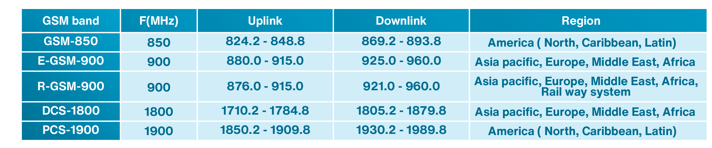
The Global System for Mobile Communications (GSM) is one of the second generation of cellular network developed in Europe. It was the most widely used cellular technology which still has global coverage. The first generation of cellular network was analog, while the second generation was based on digital technology. Therefore, in GSM, voice is converted to digital and a digital modulation for transmission is used. In terms of switching, GSM uses circuit switching for both voice and data transmission. There are two other cellular technologies that are based on GSM. The first one is called General Packet Radio Service (GPRS), which uses packet switching for its data transmission and still uses circuit switching for its voice transmission. The second one is Enhanced Data Rates for GSM Evolution (EDGE) which further enhances its packet switched data transmission to achieve higher data rate. Later on, with deployment of 3rd and 4th generation of cellular network, which supported much higher data rate, the GSM/EDGE network was mainly used for two purposes. One was for voice transmission and the other one was to serve as a fallback solution for data services. For this reason, GSM/EDGE continued to be an important part of cellular technology. Due to the fact that GSM has a good coverage around the world especially in Europe, Middle East and African countries, it can also be used for MTC as well as IoT. GSM usually works in 50 MHz spectrum in global 850, 900, 1800, and 1900 MHz depending on the region of deployment as shown in Table 3.1. Path loss depends on frequency and lower path loss can be achieved in lower frequencies. Global availability of GSM in lower frequency bands of either 850 or 900 MHz band has enabled GSM to provide a good coverage. Compared to more advanced generations of cellular networks, GSM uses a simpler technology. This means that the price of GSM mobile devices is considerably cheaper as compared to 3G, 4G and 5G technologies. This also makes GSM an attractive choice for IoT technology. For these reasons, 3GPP Release 13 considered EC-GSM-IoT as an IoT technology. In this book, we mainly focus on the other two 3GPP technologies introduced in Release 13, LTE-M and NB-IoT. These two technologies are further enhanced in newer releases and are the main focus of this book.
Table 3.1: GSM spectrum in different regions of the globe
3.3.2LTE-based cellular IoT technologies
LTE-M and NB-IoT were introduced in Release 13 of LTE technology to extend LTE with features to support MTC and IoT. These technologies later got enhanced in Release 14 and 15 of LTE technology. We first explain the legacy LTE system and then discuss LTE-M and NB-IoT.
3.3.2.1 LTE
LTE physical channel bandwidth can be 1.4, 3, 5, 10, 15, and 20 MHz. Mobile Network Operators (MNOs) have the option to deploy LTE with one of these bandwidths. For example, if the MNO deploys LTE with 10 MHz physical channel bandwidth, all data and signalling physical channels must be mapped to this 10 MHz bandwidth. In terms of duplexing scheme, LTE supports both Frequency Division Duplexing (FDD) and Time Division Duplexing (TDD) for its uplink and downlink transmissions.
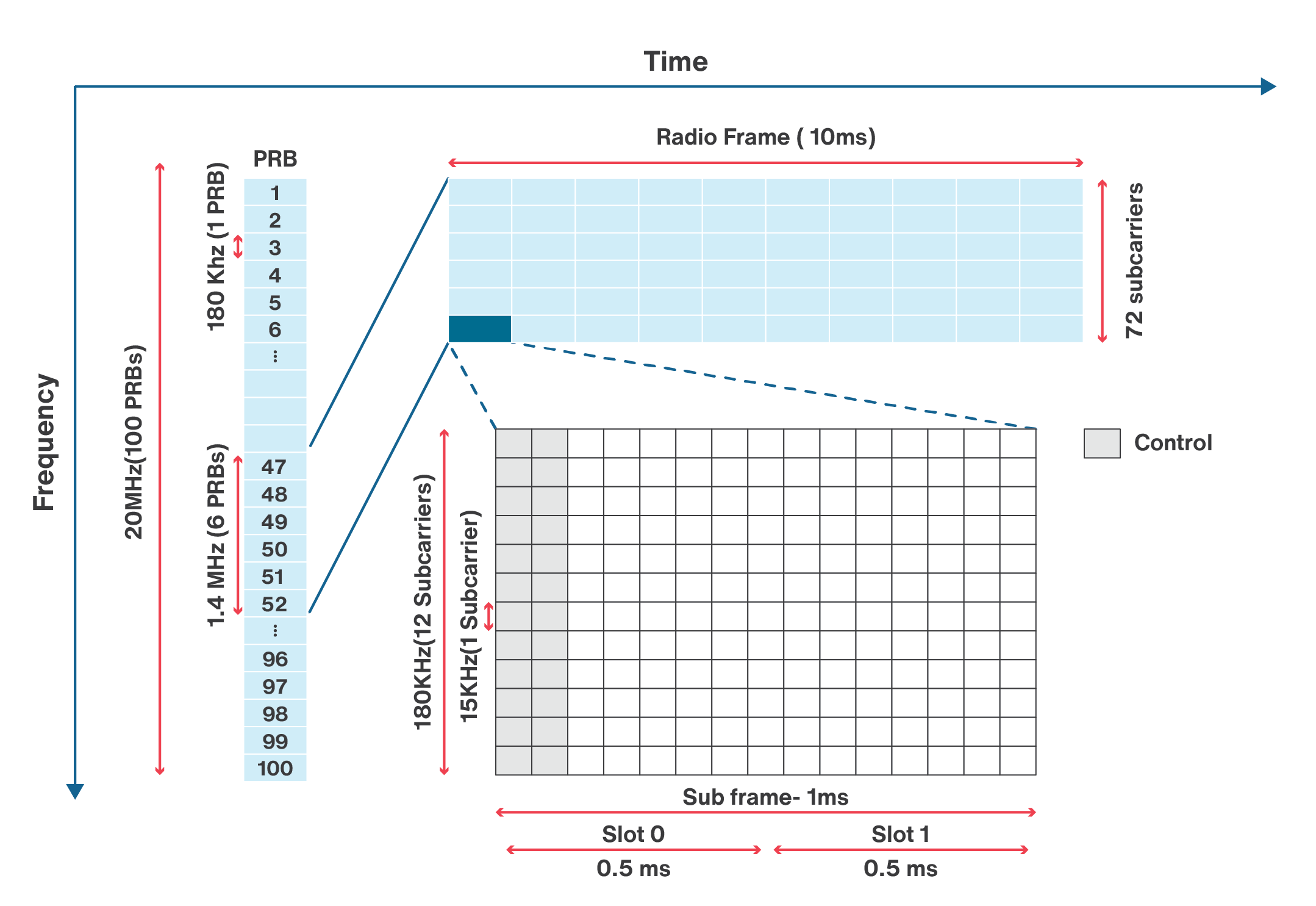
We should look at the physical channel both in terms of time and frequency. From the time perspective, physical channel is divided into radio frames. Each radio frame is composed of 10 sub-frames. Each of these sub-frames consists of two time slots. Each time slot is 0.5 msec. Therefore, the duration of a radio frame is 10 msec. From the frequency perspective, the bandwidth of LTE physical channel is divided into what is called Physical Resource Blocks (PRBs). The bandwidth of each PRB is 180 KHz. Each resource block consists of 12 subcarriers. These subcarriers are separated by 15 KHz. Therefore, with transmission bandwidth of 1.4 MHz, there will be 6 PRBs, while there exist 100 PRBs with the maximum bandwidth of 20 MHz. Each radio frame contains user data, control information, and synchronization information.
To reduce the interference with neighboring bands, some part of the bandwidth is considered as guard band. The guard band occupies 10% of the bandwidth if the available channel bandwidth is 3, 5, 10, 15, or 20 MHz except for 1.4 MHz implementation where the guard band occupies 23%. For example, in 1.4 MHz bandwidth deployment, there are 6 PRBs, each occupying 180 KHz. This makes 1.08 MHz out of 1.4 MHz of the bandwidth, which is 77% of the total bandwidth. Therefore, 23% of the bandwidth is used for guard band. In case of 20 MHz bandwidth, there are 100 PRBs which occupy 18 MHz out of 20 MHz bandwidth. Therefore, 2 MHz, or 10% of the total bandwidth is allocated for the guard band.
An example of downlink radio frame structure is shown in Figure. 3.2. As you can see in this figure, each radio frame has ten sub-frames. Since each sub-frame is divided into two slots, each radio frame has 20 slots. The duration of each slot is 0.5 ms. So the duration of each sub frame is 1 ms. The duration of a radio frame is 10ms. Also, it can be seen that a PRB has 12 subcarriers of 15 KHz. Therefore, there is 72 subcarrier in the 1.4 MHz deployment scenario.
The downlink, and similarly uplink are composed of different channels. What is called a channel represents specific locations in each radio frame that carries data or specific type of control information. The information in different channels might be coded or modulated differently. For example, we will see later that a specific signaling information may exist in specific sub-frames and for this reason not all sub-frames are the same. Some channels may exist in all sub-frames, while some of them only occupy specific sub-frames or slots of a sub-frame. Hereunder, we take a look at some of these channels.
The synchronization signals have their own locations within sub frames 0 and 5 of a radio frame. Downlink synchronization signals can be used for several reasons such as detecting the frame boundaries. There are two synchronization signals in the LTE. The first one is called the Primary Synchronization Signal (PSS) and the second one is called the Secondary Synchronization Signal (SSS). When an LTE phone turns on, it looks at the subcarriers of sub frame 0 and 5 to find the synchronization signals. These synchronization signals are used for frame timing acquisition and cell differentiation.
Downlink Control Information (DCI) contains the required information to control the downlink data transfer. The physical channel for carrying DCI is called Physical Downlink Control Channel (PDCCH). DCI can use different size symbols based on the parameters such as bandwidth, or frame structure. The number of symbols that carry the DCI in a sub-frame is defined in the Physical Control Format Indicator Channel (PCFICH). The control information such as PDCCH and PDCFICH are located within the first slot (Slot 0) of each sub-frame and occupy up to three columns. The number of control columns is different in each sub-frame.
The user data is carried using the Physical Downlink Shared Channel (PDSCH). In each sub frame, the columns for PDSCH information are located after the columns for the control information.
Master Information Block (MIB) has the essential cell parameters such as bandwidth and frame timings. MIB exists in the Physical Downlink Broadcast Channel (PBCH) which is located within the first sub-frame (Sub-frame 0). When a phone is turned on, it does not know the bandwidth deployment of the operator. So, the phone needs to find this information by reading the MIB. The MIB is sent over four radio frames. The MIB information can be decoded from each of these radio frames. Therefore, there is no need to wait for all 4 frames, if the signal is strong enough.
The Automatic Repeat Request (ARQ) information is located in the Physical Hybrid Automatic Repeat Request Indicator Channel (PHICH). LTE uses ARQ scheme for error correction. The tower sends a Hybrid Automatic Repeat Request (HARQ) indicator to the cellphone to indicate a positive acknowledgement (ACK) or negative acknowledgement (NACK) for the data sent using the uplink shared channel. These indicators are transmitted through the PHICH.
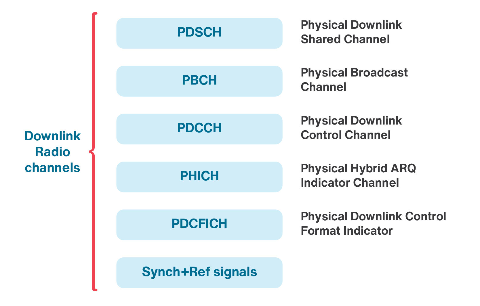
There are four downlink reference signals CRS, DM-RS, CSI-RS, and PRS. These reference signals are necessary for data demodulation and are located throughout the data and control channels. PDSCH and four other physical channels (PDCCH, PHICH, PDCFICH, and PBCH provide all the user data, control information, and system information needed for unicast data transmission. All these channels are shown in Figure 3.3.
The uplink radio frame and sub-frame structure in both time and frequency are similar to the downlink frame. In terms of channels, there are several uplink physical channels in LTE. We now discuss these channels.
- Physical Random Access Channel (PRACH) is used for initial access of an IoT device to the network. Using this channel, the random access preambles are sent in the uplink direction. The IoT device uses PRACH to transmit a preamble to initiate random access.
- Physical Uplink Control Channel (PUCCH) carries the uplink control information (UCI), including scheduling requests, acknowledgments (ACKs/NACKs), and reports of measurements for the downlink channel.
- Physical Uplink Shared Channel (PUSCH) carries the user data transmitted by UE. It should be noted that the UE should have received an uplink scheduling grant before its data is transmitted through PUSCH.
- There are a couple of uplink reference signals in uplink radio frame. One is the Demodulation Reference Signals (DMRS) and the other one is the Sounding Reference Signal (SRS). DRMS is used for channel estimation and demodulating the uplink control and data information. SRS enables the scheduler to allocate the data to portions of the uplink bandwidth where the channel responses are better.
We discussed briefly some of the main downlink and uplink channels in legacy LTE to give the reader an understanding of the frame structure and channels in LTE.
3.3.2.2 LTE-M
LTE-M tries to modify and optimize the LTE technology to achieve deeper coverage, lower power consumption, longer battery life, lower device cost, and larger device density per cell without loosing capacity. LTE-M technology modifies the legacy LTE to ensure that the technology is suitable for IoT applications in terms of performance and functionality.
As we mentioned in the previous section, scalable carrier bandwidths from 1.4 MHz to 20 MHz, utilizing 6 to 100 resource blocks are supported by LTE. LTE-M uses part of the existing bandwidth for IoT. The bandwidth of LTE-M in Release 13 was limited to 1.4 MHz (1.08 MHz plus guard-band). It should be noted that the LTE-M network supports two Coverage Enhancement (CE) modes, the mandatory mode A and the optional mode B. CE mode A supports only moderate coverage enhancements, while mode B supports very deep coverage. LTE-M also supports a maximum data channel bandwidth of 5MHz in uplink. The control signaling is still restricted to 1.4 MHz in order to re-use as much as possible of the Rel-13 design. There is no change in duplexing scheme in this release. The LTE-M bandwidth is increased to support maximum channel bandwidths of 5 or 20 MHz for mode A and mode B in downlink, respectively.
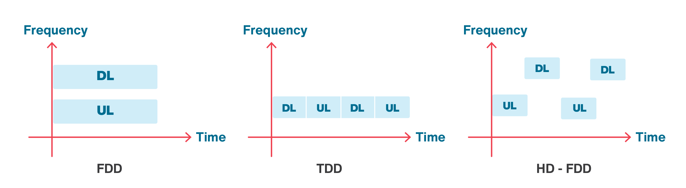
To reduce complexity, LTE-M devices can support half-duplex communications. LTE-M in Release 13, 14 and 15 support half-duplex FDD in addition to TDD. In full duplex FDD, the data transmission and reception can be done simultaneously, while in half-duplex operation, a device should alternate between transmission and reception as shown in Figure 3.4. Using HD-FDD can reduce the data rate, but devices that only support HD-FDD are less complex, and therefore, less costly.
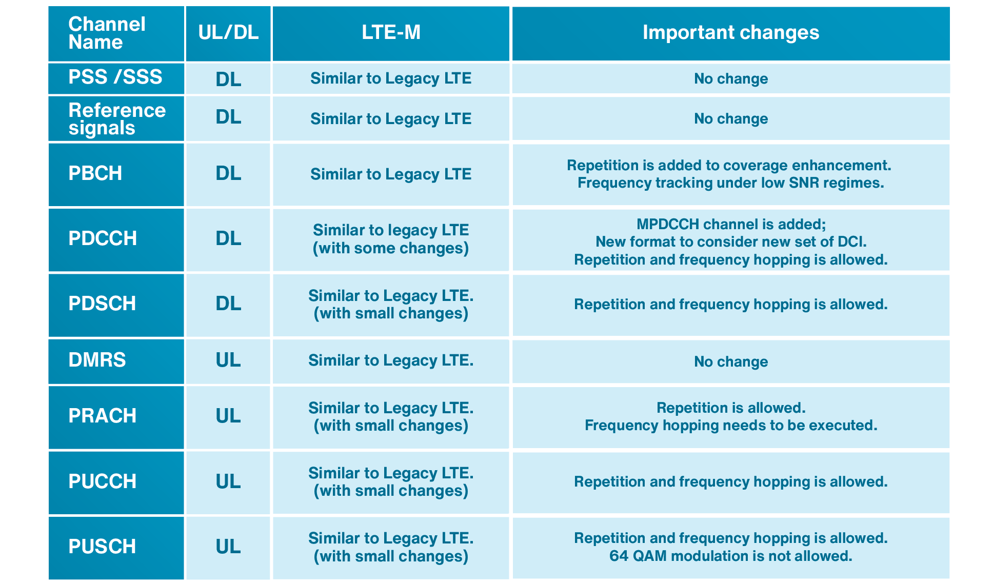
A comparison between some channels and signals in LTE and LTE-M is listed in Table 3.2. As seen in this table, the LTE-M signalling is very similar to the legacy LTE. In LTE-M, there have been more changes to PDCCH control channel compared to the other channels. In this regard, a new channel called MPDCCH which stands for MTC physical downlink control channel has been introduced. MPDCCH is a special type of PDCCH designed for IoT operation. Most channels in LTE-M are very similar to legacy LTE, except that the repetition and frequency hopping have been added to most of the channels.
Table 3.2: A comparison between some channels and signals in LTE and LTE-M
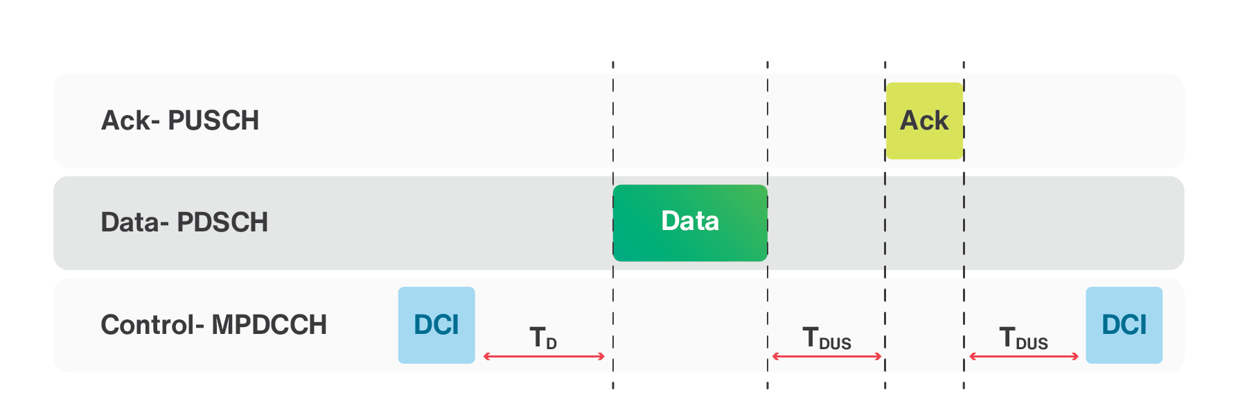
A simple example of downlink data transfer is shown in Figure 3.5. The data transfer starts with the base station sending a DCI signal to the IoT device. The base station then sends the data to the IoT device in downlink direction. The IoT device receives the data and sends an acknowledgement to the base station. There is a timing that needs to be respected during the operation. TD represents the cross sub-frame delay, while TDUS and TUDS represent downlink to uplink switching time and uplink to downlink switching time, respectively. The TD, TDUS, and TUDS values for LTE-M are 1ms, 3ms, and 3ms, respectively.

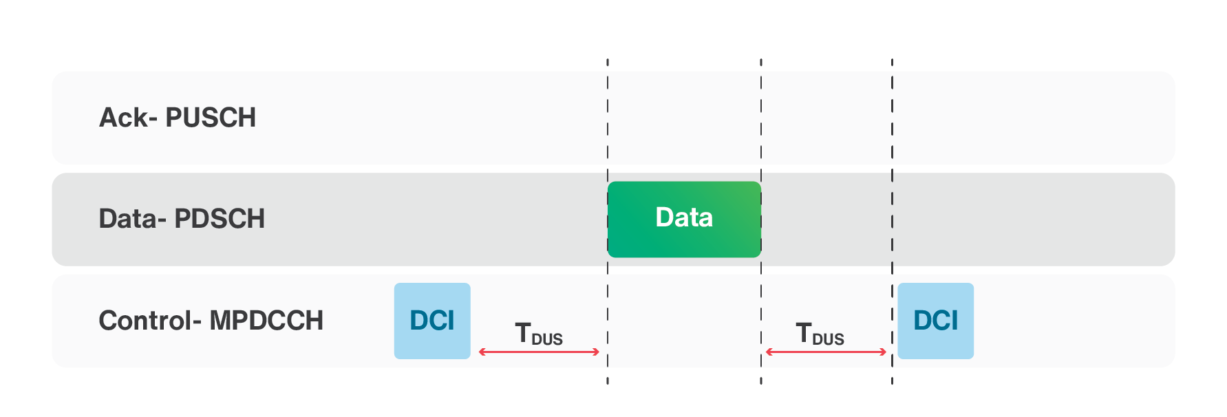
The uplink data transfer is shown in Figure 3.6. The data transfer starts with the base station sending a DCI signal to the IoT device. The IoT device then sends the data to the base station. The base station receives the data and sends an acknowledgement to the IoT device. There is a timing that needs to be respected during this operation.
To increase the data rate, the legacy LTE uses the HARQ process. The number of HARQ processes in LTE-M has been increased in some scenarios. In ARQ, when a receiver receives a corrupted packet, the receiver discards the corrupted packet and asks for a retransmission of the same packet by sending a NAK packet to the transmitter. If in the new retransmission, the packet arrives with errors, the receiver discards the packet again and requests for a new retransmission of the same packet. The HARQ technique uses the ARQ along with soft combining (an error correction technique), which does not discard the received corrupted data. In soft combining, the receiver buffers the corrupted packets and tries to perform error correction.
HARQ process for downlink in LTE-M is similar to legacy LTE except that the repetition of each transmission is allowed. However, HARQ process for uplink is different from the legacy LTE. The most critical difference is that the base station does not send any ACK/NACK. Instead of NAK in MPUSCH channel, it will send another DCI to ask the IoT device for another transmission.
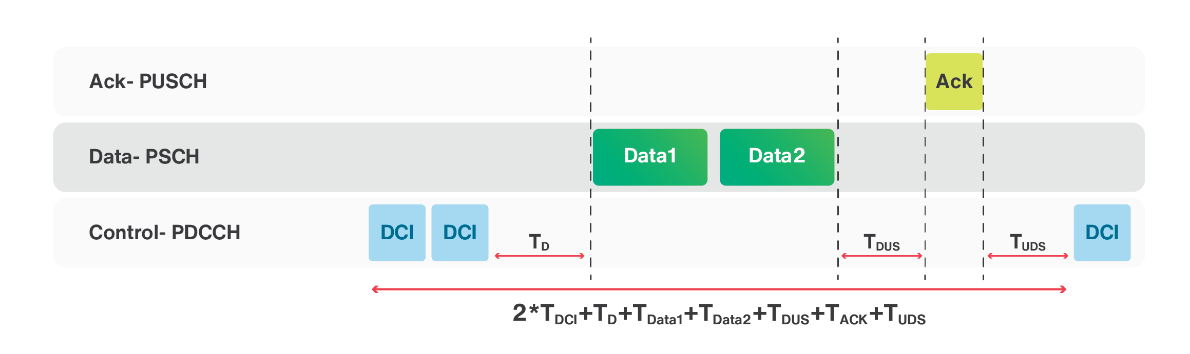
It is clear that increasing the number of concurrent HARQ processes can increase the data rate. Figure 3.7 shows 2 HARQ processes in downlink. The timing for sending two packets can be calculated as 2×TDCI+TD+TData1+TData2+TDUS+TACK+TUDS as shown in Figure 3.7, where TDCI is the time needed to send the DCI packet and TData1 and TData2 are the duration of Data1 and Data2 packets.
The peak data rate for LTE-M depends on many factors. Some of these factors are the spectrum, the Transport Block Size (TBS), and the maximum number of HARQ processes. In general, increasing the TBS value results in higher data rate. Increasing HARQ processes can also increase the data rate. However, this happens mostly in good radio conditions.
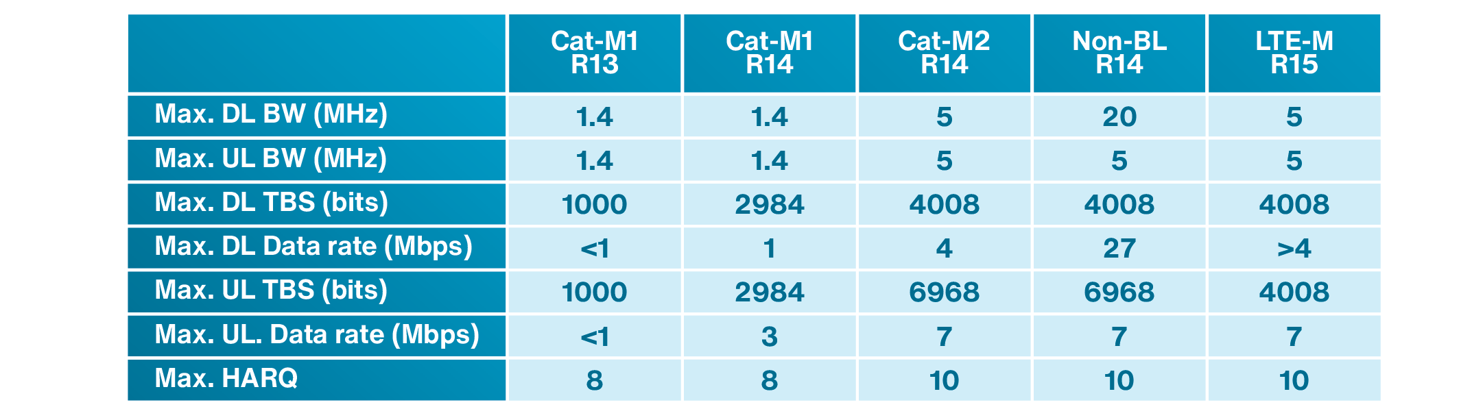
In LTE-M Release 13, the spectrum is 1.4 MHz. LTE-M Release 13 provides a theoretical peak data rate of 1 Mbps using 1000 bytes of TBS and by using eight HARQ processes in both uplink and downlink directions. LTE-M Release 14 introduces Cat-M2 devices with the spectrum of 5 MHz and allows Cat-M2 devices to use a larger TBS as compared to Cat-M1 devices. The TBS for Cat-M2 devices can be up to 6968 bytes in uplink direction and 4008 bytes in downlink direction. It can also benefit from a maximum of ten HARQ processes in downlink and a maximum of eight HARQ processes in uplink. Therefore, the peak data rate is increased to 4Mbps in downlink and 7Mbps in uplink direction. To be able to transmit more consecutive TBS in downlink and increase the peak data rate for LTE-M in HD-FDD mode, Release 14 introduced a method to bundle HARQ-ACK for several TBS into a single transmission. LTE Release 14 also introduces non-balanced (non-BL) version with a spectrum of 20 MHz in downlink and 5 MHz in uplink. In Release 15, LTE-M supports better modulation scheme to increase the data rate, while the peak data rate for the IoT device is not increased. A summary of some of the parameters related to LTE-M technology in different 3GPP releases is listed in Table 3.3.
Table 3.3: A summary of some of the parameters related to LTE-M technology in different 3GPP releases
Example 3.1:
LTE-M supports up to 52000 devices per cell in Release 13. The number of supported devices is increased substantially in higher releases. Let us consider a situation where three groups of IoT devices are connected to a given cell to transfer data. The first group contains 16000 weather monitoring devices, which send 100 bytes of data hourly. The second group consists of 16000 tracking devices, which transmit 50 bytes of data every 4 hours. The third group contains 16000 industrial machines, where each machine sends 25 bytes every 15 minutes. These devices are transferring data with an average of 7.56 kbps as shown in Table 3.4.
Table 3.4: information about three groups of IoT devices in example 3.1
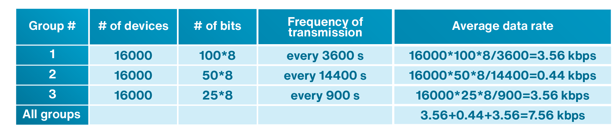
The maximum data rate of LTE-M is 1 Mbps which is much higher than the average data rate of 7.56 kbps in this case. One may think that the system can work with all IoT devices in this example without any issues. But, this is not a correct idea. Let us assume that 10% of IoT devices in each group send their data at the same time. For example, 1600 IoT devices belonging to the first group will send their data simultaneously which generates (1600×100×8) = 1.6 Mbits of data. This huge amount of data cannot be transferred with a network that can handle maximum data rate of 1 Mbps without causing any congestion. Many IoT applications are sending data when an event is triggered. In a practical situation, an emergency situation may cause many IoT devices to initiate the uplink access procedure simultaneously. Hence, we should expect degradation of system performance in such scenarios.
3.3.2.3 NB-IoT
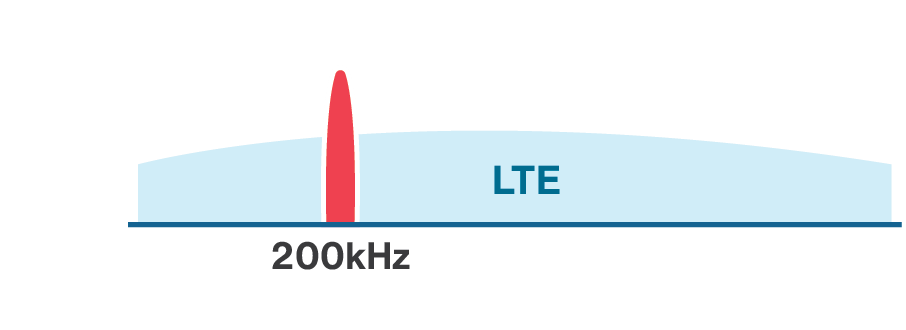
Since there are many IoT applications that send small amounts of data (lower than the amount typically transmitted by LTE-M IoT devices), a special category, called NB-IoT, has been considered in LTE specifications. NB-IoT uses a small bandwidth for data transmission and reduces the bandwidth to 200 kHz (180 kHz plus guard-band) as compared to 1.4 MHz used in LTE-M in Release 13.
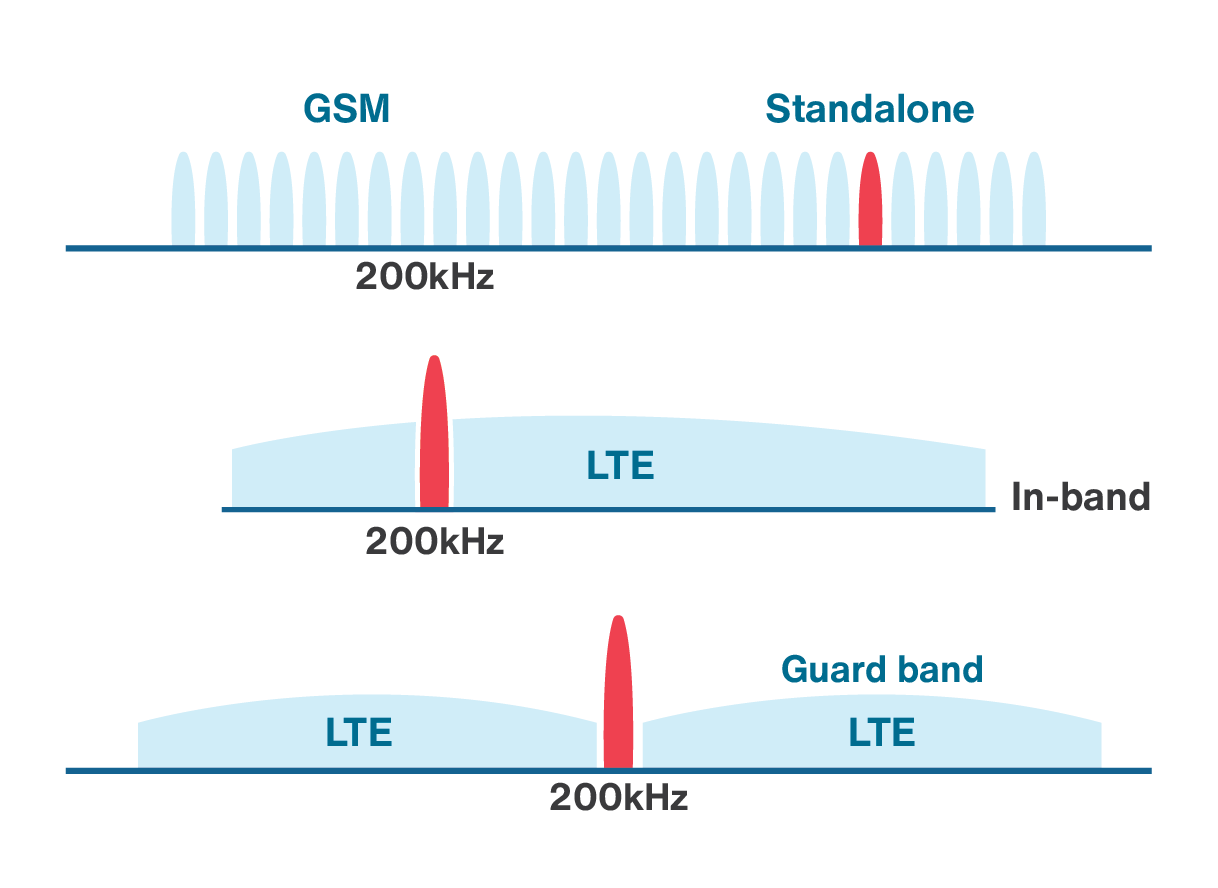
NB-IoT can be deployed in three different modes to provide the limited bandwidth required for IoT applications. The first mode of deployment is in-band mode in which one PRB in LTE spectrum is dedicated for NB-IoT both in the DL and UL. The second mode of deployment is called the guard-band mode which is similar to in-band mode, but as the name implies, the spectrum resides in the guard-band of LTE spectrum. The last mode of deployment is called standalone mode in which NB-IoT occupies a 200 KHz bandwidth in the GSM spectrum. The comparison of these three deployment modes are shown in Figure 3.8. These deployment modes provide flexibility in IoT system design and enable the integration of 4G, 3G and 2G cellular technologies for IoT connectivity.
One of the objectives of NB-IoT is to provide connectivity to massive number of IoT devices. For this purpose, in NB-IoT a Resource Unit (RU) can be allocated to multiple UEs, while the legacy LTE network allocates an RU only to one IoT device in the uplink.
NB-IoT can also use either a 15 kHz or 3.75 kHz subcarrier spacing in uplink. The base station decides which subcarrier spacing needs to be used. In case of 15 kHz subcarrier spacing, the resource grid for the uplink is similar to downlink, while the resource grid for a slot in a 3.75 kHz subcarrier spacing has a modified structure. The symbol duration for 3.75 kHz subcarrier spacing has four times the symbol duration compared to 15 kHz, which results in a slot length of 2 ms.
For coverage enhancement and providing connectivity to the IoT devices located in poor radio connection, NB-IoT has an additional coverage of 20 dB as compared to the legacy LTE network. This is done by repetitions of up to 128 in uplink and up to 2048 repetitions in downlink direction. It is clear that repetition increases the delay, and enhancing the coverage comes at the expense of an increase in latency.
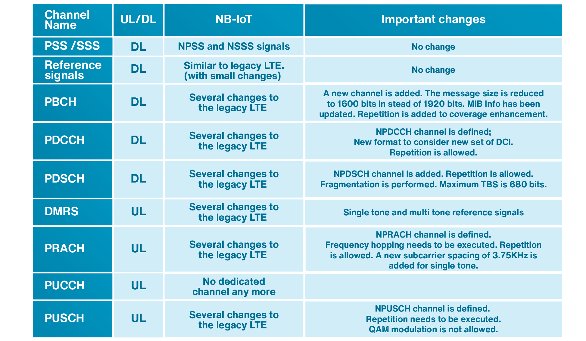
A comparison between some channels and signals in LTE and NB-IoT is listed in Table 3.5. As seen in this table, the NB-IoT has made substantial modifications to the LTE signaling and has introduced many new channels in contrary to LTE-M which is very similar to the legacy LTE.
Table 3.5: A comparison between some channels and signals in LTE and NB-IoT
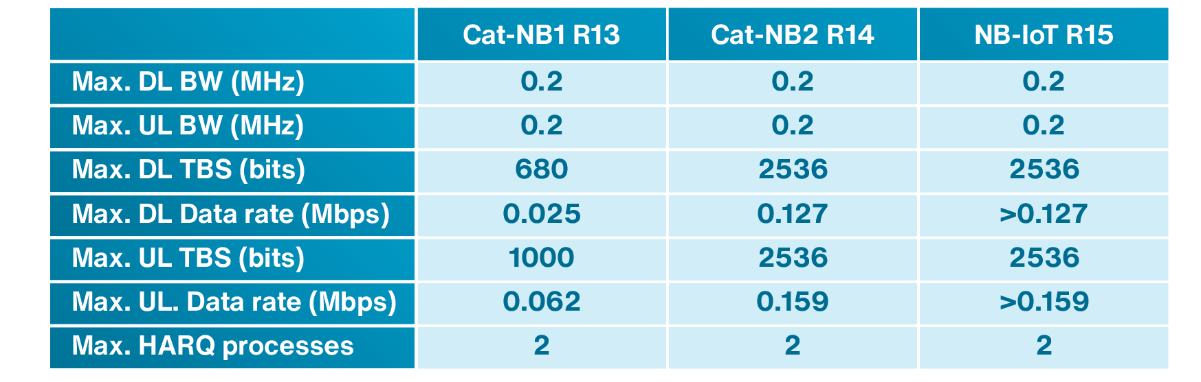
NB-IoT Release 14 supports a maximum of 2536 bits as TBS in either uplink or downlink using one HARQ process. It also supports a maximum of two HARQ processes with 1352 and 1800 bytes in uplink and downlink, respectively. For NB-IoT Release 14, the downlink peak data rate is 80 kbps and the supported uplink peak data rate is 105 kbps. NB-IoT optimizes the signaling of small-sized data to increase the network capacity to serve very large number of devices. Table 3.6 compares some of the NB-IoT parameters in different NB-IoT releases.
Table 3.6: comparison of NB-IoT parameters in different NB-IoT releases.
Chapter 3 Exercises
- Which sentence is correct about the spectrum and data rate of the LoRaWAN and Sigfox?
- The spectrum of the LoRaWAN is larger and its data rate is higher than Sigfox.
- The spectrum of Sigfox is larger and its data rate is higher than the LoRaWAN.
- LoRaWAN uses larger spectrum than Sigfox, but has adaptive data rate and therefore its data rate might be higher or lower than Sigfox.
- LoRaWAN uses smaller spectrum than Sigfox. However, since it is using a better modulation technique has higher data rate.
- Which of the following technologies can be used for tracking of a car in a city?
- NB-IoT Release 13.
- LTE-M.
- Sigfox.
- LoRaWAN.
- Is LoRaWAN a cellular wide area network?
- Yes, it is cellular. LTE-M, NB-IoT, and Sigfox are cellular as well.
- Yes, it is cellular. LTE-M, NB-IoT are cellular, but Sigfox is not cellular.
- No, it is not cellular. LTE-M, NB-IoT, and Sigfox are cellular as well.
- No, it is not cellular. LTE-M, NB-IoT are cellular. But, Sigfox is not cellular.
- What is the difference between LoRa and LoRaWAN?
- They are the same.
- LoRa defines the physical layer of the system, LoRaWAN defines the protocols over LoRa and it is the network architecture which operates in a non-licensed band.
- LoRa defines the gateway architecture, LoRaWAN defines the protocols from gateway to a WAN.
- LoRa is developed by LoRa Alliance and LoRaWAN by Semtech.
- What spectrum is used in LTE development? What about LTE-M?
- LTE uses 1.4, 3, 5, 10, 15, or 20 MHz spectrum. LTE-M always uses 1.4 MHz.
- LTE uses 1.4, 3, 5, 10, 15, or 20 MHz spectrum. LTE-M uses 1.4 in Release 13 and 5 MHz in Release 14 and above.
- LTE uses 15 or 20 MHz spectrum. LTE-M always uses 1.4 MHz.
- LTE uses 15, or 20 MHz spectrum. LTE-M uses the same as LTE.
- The signaling channels used for LTE-M are …
- exactly the same as LTE.
- completely different than LTE.
- very similar with some differences.
- mostly different, but there are a few similarities.
- The signaling channels used for NB-IoT are …
- exactly the same as LTE.
- are completely different than LTE.
- are very similar with some differences.
- are mostly different, but there are a few similarities.
- What does Half Duplex –FDD (HD-FDD) mean?
- The duplexing is FDD , but spectrum is half of entire spectrum.
- The duplexing is FDD, but the data transmission and reception can be done simultaneously.
- The duplexing is FDD, but the device should alternate between transmission and reception.
- The duplexing is FDD half of the time, and the other half can be anything else such as TDD.
- What is the duration of each LTE radio frame? Each radio frame is divided into how many sub-frames?
- 10 ms, 10.
- 100 ms, 100.
- 10 ms, 100.
- 100 ms, 10.
- What is the Physical Random Access Channel (PRACH) used for in the LTE-M system?
- Access permission of an IoT device to the network for initiating data transfer.
- Sending scheduling requests.
- Sending reference signals.
- Sending data packets.
- A simple example of downlink data transfer is shown below. The data transfer starts with the base station sending a DCI signal to the IoT device. The base station then sends the data to IoT device. The IoT device receives the data and sends an acknowledgement to the base station. There are timings that need to be respected during the operation which are called and . What is the range of duration of TD, TDUS and TUDS?
- One to several microseconds.
- One to several milliseconds.
- Tens of milliseconds.
- One to several seconds.
- What NB-IoT deployment is shown below?
- In-band.
- Standalone.
- Guard-band.
- Out of band.
- NB-IoT has an additional coverage of 20 dB as compared to the legacy LTE network. How is this 20dB achieved?
- By increasing the transmit power.
- By changing the frame structure.
- By introduction of repetitions.
- All of the above.
Chapter 3 Review Questions
- What standards are developed by 3GPP?
- Does a 3GPP release number represent a specific cellular technology?
- GSM is an older technology. Why GSM is still an attractive choice for IoT technology?
- Compare LTE-M and NB-IoT in terms of data rate, spectrum and mobility.
Answers to Exercises and Review questions are located at the end of the book: Chapter 3 Answers
