Sim Labs
3 Power Plant Efficiency
Learning Objectives
Operate the Plant at full generating capacity and compute the Power Plant Efficiency when the plant is operating:
- Under normal conditions,
- With the cooling water temperature very high (lake water temperature: 35°C),
- Without regeneration.
Theory
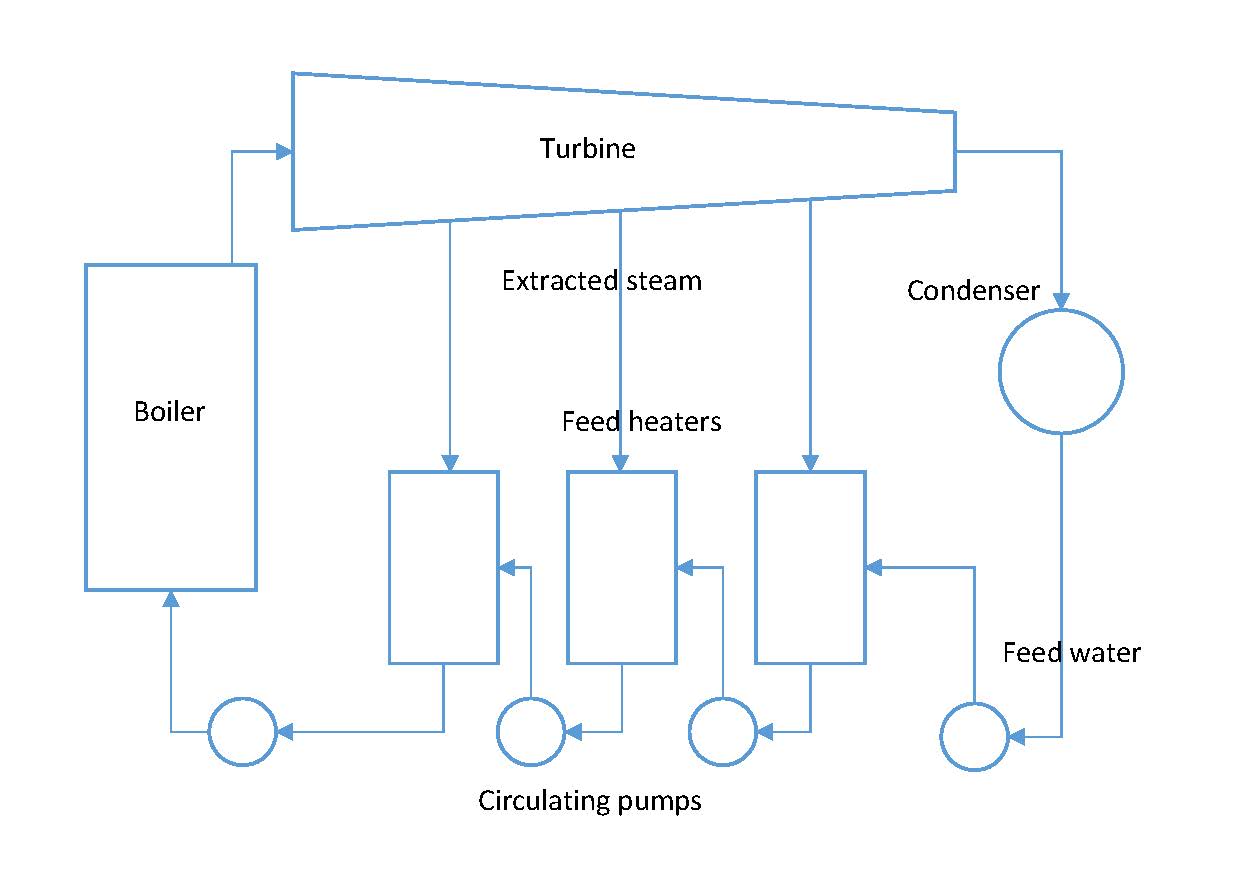
Excluding hydroelectric power plants, most power generating plants employ a type of boiler and steam turbine. A schematic diagram of a simple steam power plant is shown below:

High-pressure steam leaves the boiler and enters the turbine. The steam expands in the turbine and does work which enables the turbine to drive the electric generator. The exhaust steam leaves the turbine and enters the condenser where heat is transferred from the steam to cooling water. The pressure of the condensate leaving the condenser is increased in the pump thereby enabling the condensate to flow into the boiler. This thermodynamic cycle is known as the Rankine Cycle.
The Rankine Cycle Efficiency
As noted above, some heat is always lost from the steam to cooling water. In addition, feed pumps consume energy thus reducing the net work output. Rankine Cycle Efficiency then can be expressed as:

or

referring to the diagram above and using the enthalpy values in the Rankine cycle, we can write:

Improvements to the Rankine Cycle Efficiency
Effect of Pressure and Temperature on the Rankine Cycle
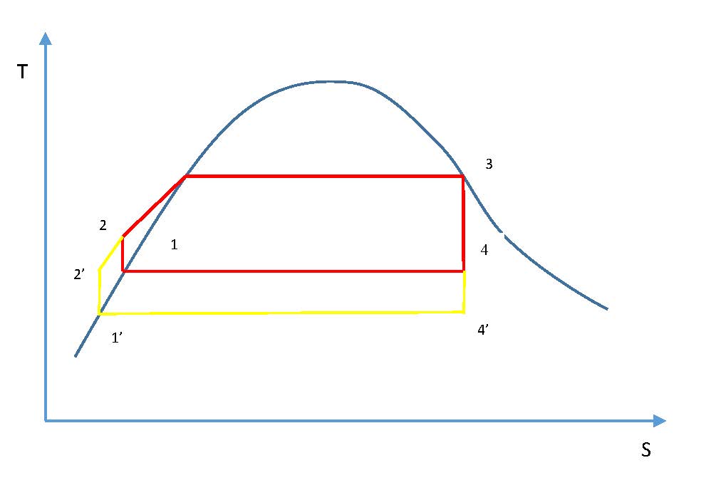
If the exhaust pressure drops from P4 to P4‘ with the corresponding decrease in temperature at which heat is rejected in the condenser the net work is increased by area 1-4-4′-1′-2’-2-1 (see diagram below)
In a similar way, if the steam is superheated in the boiler, it is evident that the work is increased by area 3-3′-4′-4-3 (see diagram below):
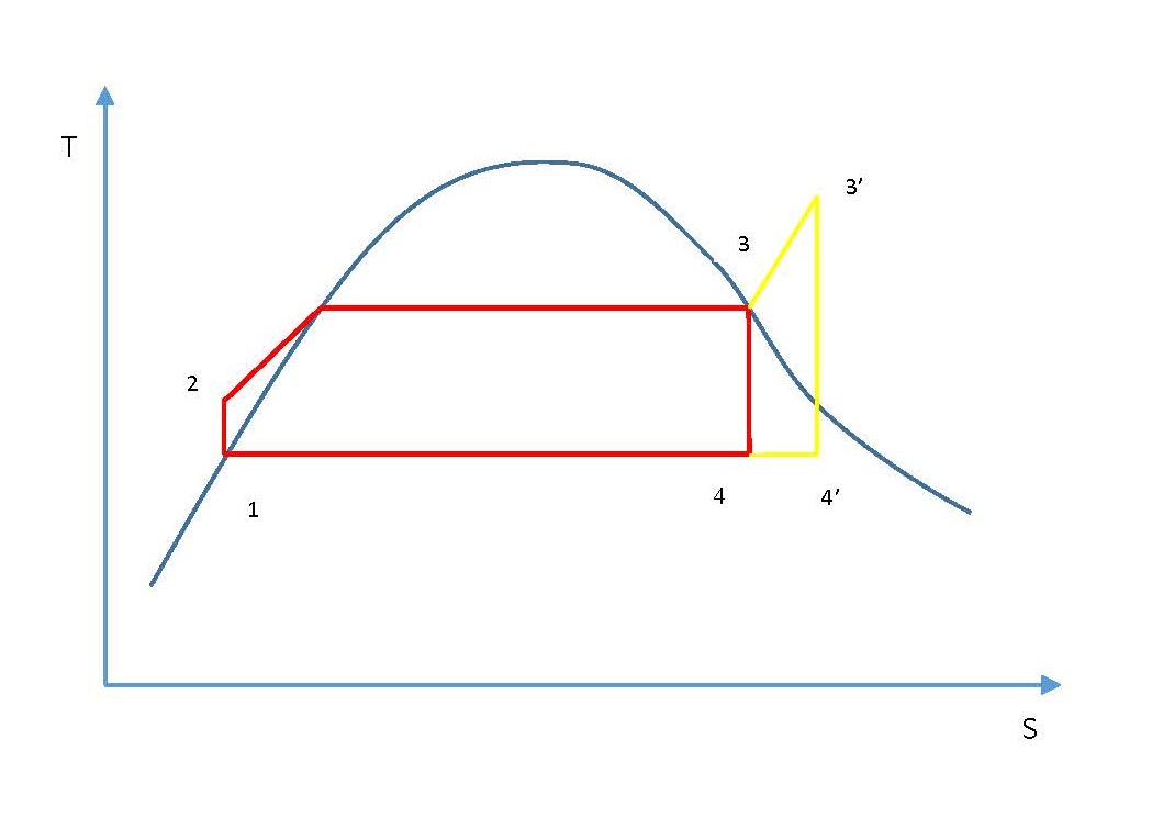
Superheating the steam is done by increasing the time the steam is exposed to the flue gases. The result of superheating is that for a given power output, the plant using superheated steam will be of smaller size than that using dry saturated steam.
The Reheat Cycle
Above we noted that the efficiency of the Rankine cycle is increased by superheating the steam. If metals could be found that would allow us to reach higher temperatures, the Rankine cycle could be more efficient. To improve the efficiency, the reheat cycle has been developed which is shown schematically below:
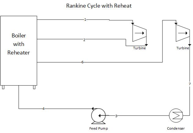
In this cycle, the steam is expanded to some intermediate pressure in the turbine and is then reheated in the boiler, after which it expands in the low-pressure turbine to the exhaust pressure. Rankine Cycle with reheat thermal efficiency can be expressed as:

The Regenerative Cycle
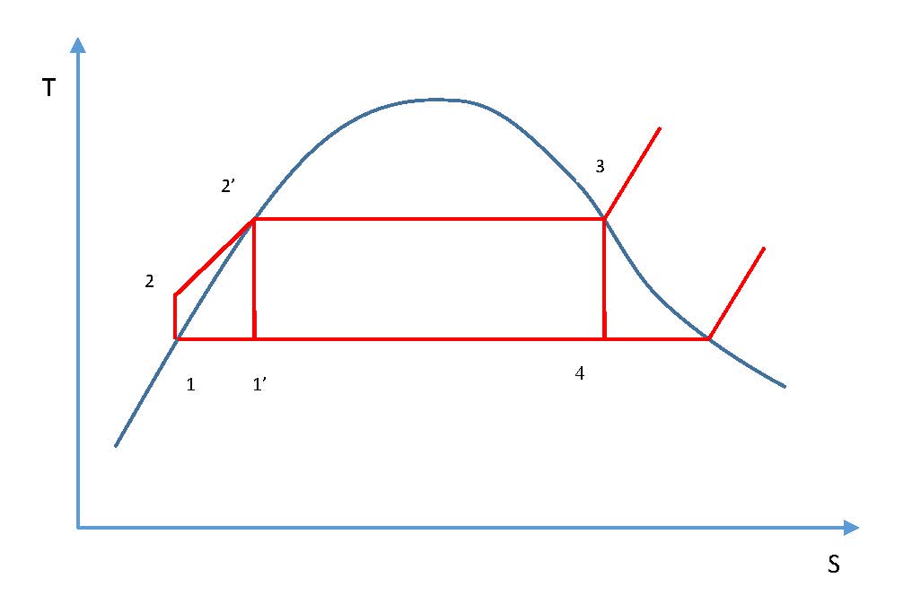
Another variation from the Rankine cycle is the regenerative cycle, which involves the use of feedwater heaters. During the process between states 2 and 2′ the feedwater is heated and the average temperature is much lower during this process than during the vaporization process 2′-3. In other words, the average temperature at which heat is supplied in the Rankine cycle is lower than in the Carnot cycle 1′-2′-3-4-1′, and consequently the efficiency of the Rankine cycle is less than that of the corresponding Carnot cycle. The relationship between Carnot cycle and Rankine cycle is shown below.
In the regenerative cycle, feedwater enters the boiler at some point between 2 and 2′. As a result, the average temperature at which heat is supplied is increased. A schematic of practical cycle is shown below:
The Plant Thermal Efficiency
In order to calculate the overall plant thermal efficiency, we need to adjust the formulas above to incorporate heat added in the reheater sections of the boiler:

Lab Instructions
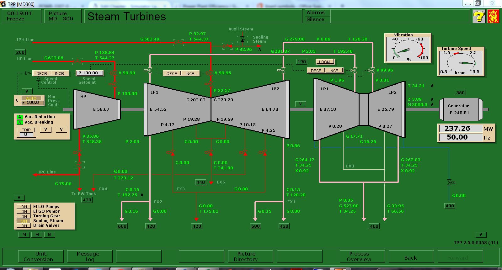
Run the initial condition I10 230 MW_oil_auto:
- Draw a T-S diagram of the Rankine cycle (not to scale) including reheat and regeneration,
- Using Trend Group Directory, collect the relevant process values,
- Calculate the overall thermal efficiency of the plant:
- Under normal conditions,
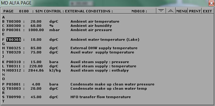
- When the cooling water temperature is very high (Set the Variable List Page 0100, tag#: T00305 to 35°C),
- When all the steam extraction valves are closed (i.e. no regeneration and T00305 set to 10°C).
Hints & Tips
In this lab, you are essentially calculating the Rankine Cycle thermal efficiency. However, you need to take the reheat cycle into consideration and log the following tags in your trends:
- Q02395 Reheater 1 transferred heat
- Q02375 Reheater 2 transferred heat
For Boiler Feedwater Inlet Temperature, you may use the Startup Heat Exchanger Feedwater Outlet Temperature tag#: T02447.
For the second calculation, locate the Variable List Page 0100 as shown below:
For the third calculation, make sure you closed all steam extraction valves and set T00305 to 10°C:
To calculate the enthalpy values, you may use an app or online tool such as the Superheated Steam Table: https://goo.gl/GdVM4U
Deliverables
Your lab report is to include the following:
- T-S diagram: As per instructions above,
- Trend plots: Supply all plots taken for this lab,
- Computation: Use MATLAB or MS Excel and calculate the overall thermal efficiency of the plant as per Lab Instructions.
- Conclusion: Write a summary (max. 500 words, in a text box if using Excel) comparing your results and suggestions for further study.
Further Reading:
- Applied Thermodynamics for Engineering Technologists by T. D. Eastop and A. McConkey: Steam Plant.
- Fundamentals of Classical Thermodynamics SI Version by G. J. Van Wylen and R. E. Sonntag: Vapor power cycles.
- Thermodynamics and Heat Power by I. Granet: Vapor power cycles.
