30 Hole Layout
In industry hole lay out is a big part of many welders’ and fitters’ daily tasks.
The weld access hole or rat hole is a structural engineering technique in which a part of the web of an I- beam, Stringer or T-iron, is cut out at the end or ends of the beam. The hole in the web allows a welder to weld the flange to another with a continuous weld on the interior/web side of flange welds. Without the weld access hole, the middle of the flange would be blocked by the web and inaccessible for welding.
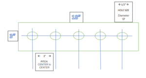
The symbol used for a hole is the diameter ‘Ø’ symbol.
Ø
Other hole lay out possibilities in industry:
- Flange Hole Lay Out
- Weep holes for drain and man hole covers
- Bolt Hole Lay Out
- Plug Welds to secure to metal (Plug welds secure the middle of plates etc., and are most often seen on wear plates and sacrificial/expendable parts like wear strips on excavator buckets.)

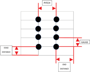
Pitch and Gauge
Width of hole w = smallest dimension, i.e. diameter of round hole, edge length of square hole, and width of long hole.
Length of hole l = length of long hole (largest internal dimension).
Pitch of holes t: The pitch is defined as the distance from center of hole to center of hole in two adjacent rows.
Width of bridge c: This signifies the smallest unperforated space between 2 holes in adjacent rows.
Note: t = w + c
Move up drill bit sizes – called stepping up
*Start hole in a precise location
Double check measurements with a trammel point.