Electric Circuits
Using Meters for Simple Circuit Measurements
Electricity is something that cannot be seen. We can only see the effects of it.
When a circuit is not operating correctly, it is very difficult to look at it and discover what is wrong.
Meters are used to measure the effects of electricity. Meters are precision instruments that can be damaged easily so certain precautions must be taken:
- Shock and vibration should be avoided.
- Temperature, humidity, and dust should be considered.
- Magnetic fields: A tray magnetic field can cause inaccurate readings.
Precautions When Using Meters
Observe the following precautions:
- Never use an ohmmeter on a live circuit because an ohmmeter is its own power source. You will at best get an inaccurate reading, at worst damage the meter or yourself.
- Match the meter to the supply. If you are working with DC then use a DC meter; if working with AC then use an AC meter.
- When working with any DC meter, always observe proper polarity when connecting it to the circuit.
- Check that the meter is oriented correctly to be read. Some are meant to be read sitting up and others are meant to be read lying down.
- Read the meter looking straight at it to avoid parallax error.
- When finished with a meter, switch it off.
Voltmeters

Voltmeters are giant resistors that draw minimal current from the source. Voltmeters are meant to measure the potential difference between two points.
The meter must be connected in parallel with the load.
It is a good idea to test the voltmeter on a known circuit first.
Ammeters
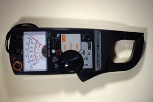
Ammeters are designed with low resistance so they do not add unwanted resistance to the circuit.
Connect an ammeter in series with the circuit. If connected in parallel, it would cause a short circuit and blow the fuse in the meter.
Wattmeters
The wattmeter has four test leads. Two are for current and two are for voltage.
Power is the product of both the voltage and the current so the wattmeter measures the effects of both and multiplies them to give the power.
Connect the voltage coil in parallel with the load.
Connect the current coil in series with the load.
Do not exceed the power rating of the meter.
Ohmmeters
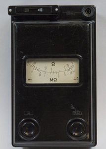
Ohmmeters are used to measure resistance. They have their own source of EMF (battery) and must not be used on a live circuit.
The scale on most ohmmeters reads backwards to other meters. Zero is on the right and infinity is on the left.
Many ohmmeters will have a zero adjustment. Always zero the meter before using. Do this by shorting the two leads together.
Electrical Meter Safety
The video below explains how not all electrical meters are created equal. Make sure you understand the ratings of your meter and what situations it can be used in.
Video!
