Chapter 2: LTE-M Modem and AT Commands
2.1 Introduction
In the previous chapter, we briefly discussed different building blocks (layers) of an IoT solution from the core functional perspective. In this chapter and the next few chapters, we will discuss how to practically work with an LTE-M module to establish a CIoT connectivity scheme to transfer the data to the Internet. The high level architecture of the IoT project that we want to complete in this book is described in Figure2.1.
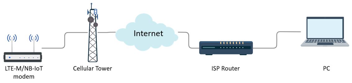
In this project, we will be using a Quectel BG96 LTE-M modem to exchange the data with the Internet through the cellular tower. The transmitted data is then stored and analyzed in the software backend (cloud platform) that gives full accessibility to the user to monitor, control and manage the device and network.
Following the step-by-step instructions in this chapter, you will become familiar with the TELUS IoT Starter Kit and Avnet Quectel BG96 LTE Cat-M1/NB-1 Shield. Also, you will be able to configure the Quectel BG96 modem using AT commands (instructions used to control a modem). Moreover, you will learn how to enable the GPS and acquire the location information using the AT commands.
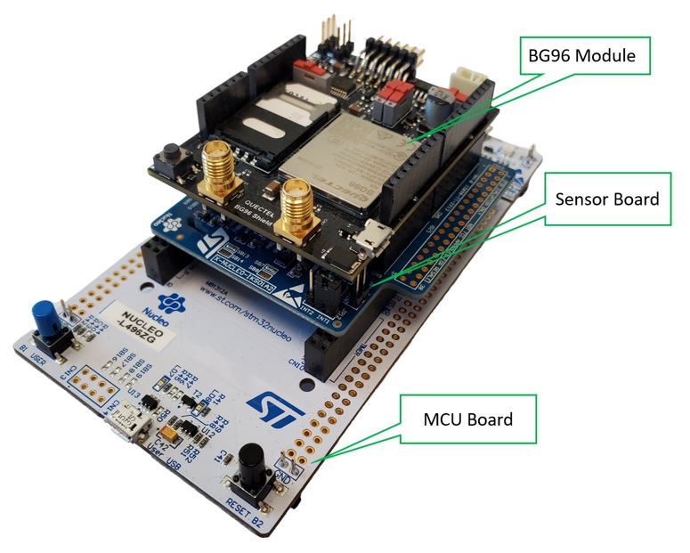
In these lab series, you will learn how to create, prototype and develop an IoT product using the TELUS LTE-M IoT Starter Kit[1]. You will practice how to connect to the LTE-M network (The modem supports both LTE-M and NB-IoT. However, in this book, you will only work with LTE-M). Then, you will use Microsoft Azure cloud services to manage, store and analyze the data. The starter kit integrates three stacked boards as shown in Figure 2.2. A brief introduction of each board is given here. Note that in this book you will only work with the BG96 module (top board) in the standalone mode.
2.2 Practical Tasks
A. BG96 Module
BG96[2] is a series of ultra low-power (approximately 10 µA in PSM mode) dual-mode LTE Cat-M1/Cat-NB1/EGPRS module manufactured by Quectel Wireless Solutions. The maximum uplink (UL) and downlink (DL) data rates for this module are 375kbps and 300kbps, respectively. This module is certified by the major mobile network operators in the world (TELUS, Bell and Rogers in Canada) and has wide range of IoT use cases such as asset tracking, smart cattle, etc.
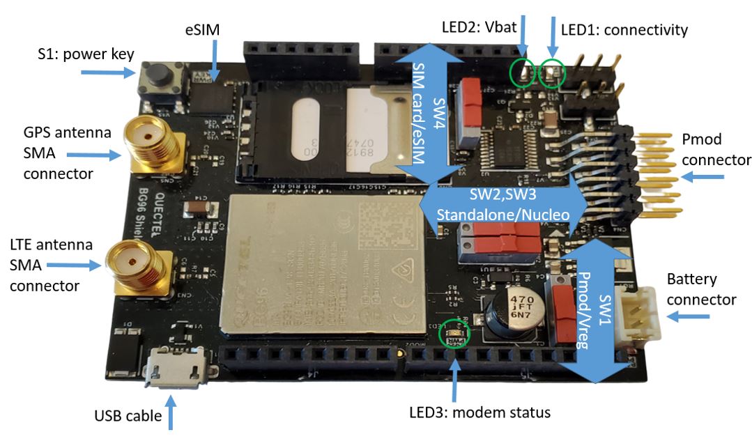
The module includes the BG96 modem and is equipped with some additional features such as SIM holder, Arduino shield interface (connectors compatible with Arduino extension boards such as WiFi), LTE and GPS antenna SMA connectors, USB port and configuration switches.
B. Sensor Board
The IKS01A2 Sensor Board[3] contains the following sensors:
- LSM6DSL[4] 3D Accelerometer and 3D Gyro Sensor
- LSM303AGR[5] 3D Accelerometer and 3D Magnetometer
- LPS22HB[6] Barometric Pressure Sensor
- HTS221[7] Relative Humidity & Temperature Sensor
The communication between this sensor board the MCU board (NUCLEO-L496ZG) is through I²C interface.
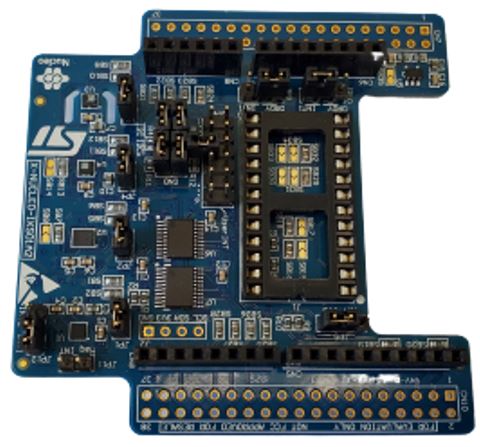
C. MCU Board
Figure2.5 shows the NUCLEO-L496ZG Microcontroller Board[8] with Arduino connectors. You can consider connecting the BG96 module to this MCU board for future IoT products.
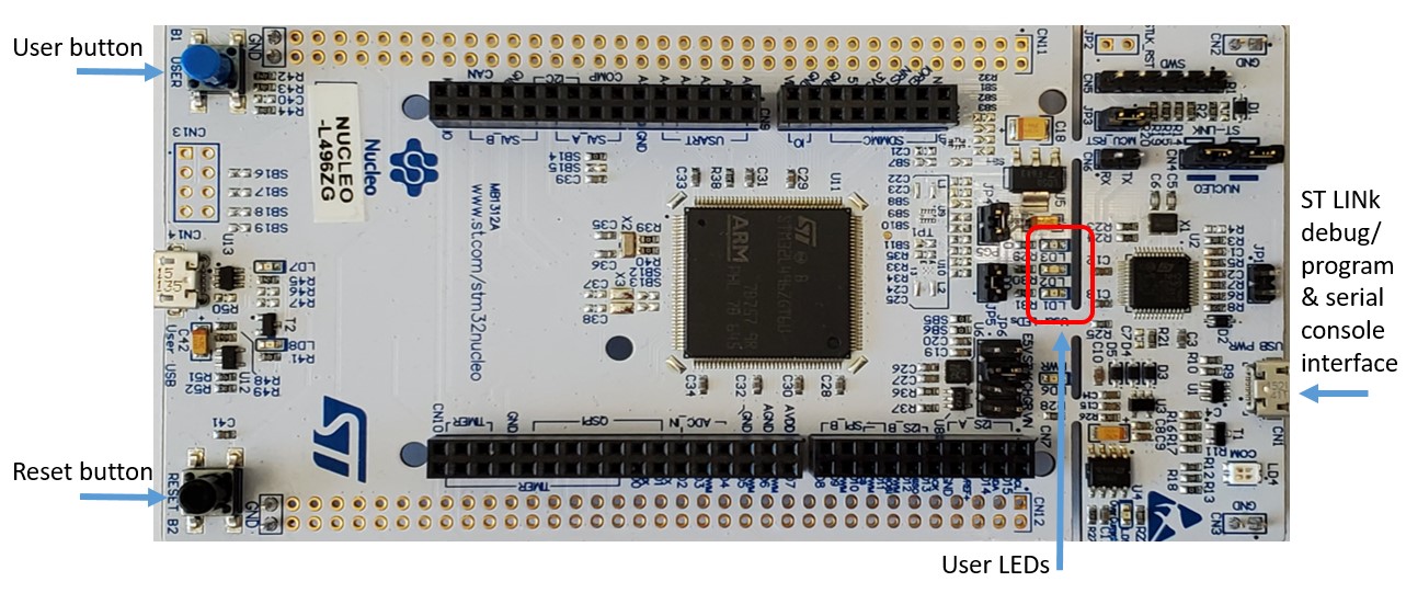
Note that in this book our focus is only on the BG96 module and we will not connect the sensor and the microcontroller boards to build the stack. If you are interested, you can build the full stack and try to send the AT commands to the BG96 module through the microcontroller board.
D. SIM card activation
In this sub-section, we discuss how to activate the SIM card for TELUS network operator. Different mobile network operators have different procedures to activate their SIM cards. If you already have an activated SIM card, skip this sub-section.
Before activating the TELUS SIM card, you need to have two codes handy:
- ICCID: Integrated Circuit Card Identifier (ICCID) is a 19-digit number located at the bottom of the SIM card.
- Starter Kit activation referral code. The referral code is provided for you at the back of the “Quick Starter Guide” page that came with TELUS LTE-M IoT Starter Kit[9] (e.g., TELU8284). If you do not have one, you can request a referral code at telus.m2m.com.
- Go to telus.m2m.com -> Click “Enter Referral Code” -> Click “Order Kit” to create your account.
- Create a username/password and enter your contact information and SIM card number (ICCID) and click continue. It may take a few days before TELUS can activate your SIM card and provide you with an Access Point Name (APN) through email. The provided TELUS APN could be “m2m-west.telus.iot” or “m2m-east.telus.iot” depending on your region in Canada. You will need this APN later when you want to connect to TELUS LTE-M network in the next chapters. An APN defines where a device will connect to the Internet. In order for a device to connect successfully to the Internet, the device application must use an APN that is allowed by the device’s communication plan.
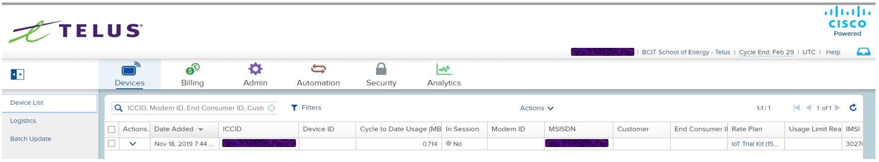
- You can log in to TELUS Control Center[10] using your username/password to manage your device (view cycle-to-date usage, modify rate plan or SIM status), access your invoices, or modify your profile.
E. Standalone modem setup
In this part of the lab you will work with the BG96 board on its own and when it is not stacked to the MCU board.
- You may detach the BG96 board from the Sensor Board and MCU Board. You can still use the BG96 board in standalone mode when it is stacked on the MCU board. However, make sure Switch S2 and S3 are positioned properly and the USB cable is connected to the USB port of the BG96 board and NOT that of the MCU.
- Slide Switch S2,S3 towards the standalone position (to the left side as shown in Figure2.7)
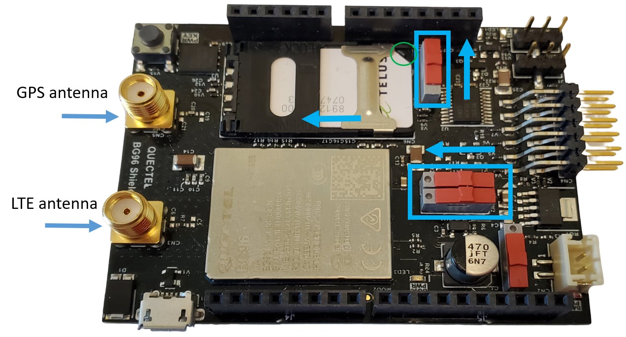
- Slide the metal retaining clip of the SIM holder, in direction of the SMA connectors (Left direction of Figure2.7), and then lift it up. Insert the activated SIM card with notched corner facing outwards. Press on the SIM holder and slide the metal retaining clip back in the direction of Pmod connector (Right direction of Figure2.7).
- Set the sliding Switch SW4 to choose the SIM card.
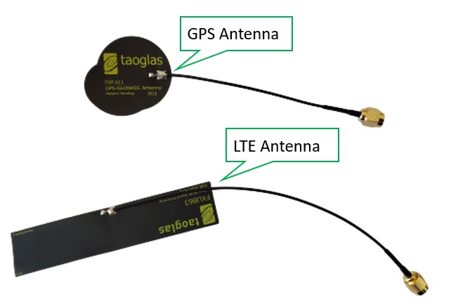
- Attach the LTE and GPS antennas to the SMA connectors.
- Connect your PC to the BG96 board’s micro USB connector.
- Press and hold Switch S1 (power key) for two seconds to wake up the modem. When the modem is awake, LED3 (modem status) should be off.
- Download and install “Quectel_LTE_Windows_USB_Driver_V1.0[11]” or the latest version.
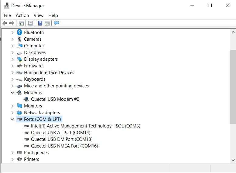
- Go to “Device Manager” -> Ports (COM & LPT). You should see three Quectel USB ports:
- Quectel USB AT port,
- Quectel USB DM port,
- Quectel USB NMEA port
F. Quectel BG96 modem configuration using AT commands
AT commands (AT is the abbreviation of ATtention) are instructions used to control a modem and start with “AT”. Quectel_BG96_AT_Commands_Manual[12] contains a full set of BG96 modem AT commands.
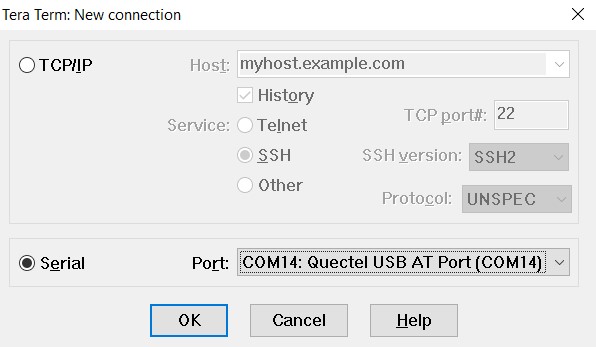
- On your PC, open a terminal communications program such as Tera Term to emulate different types of computer terminals. If you do not have Tera Term installed on your PC, you can download the latest version at: https://osdn.net/projects/ttssh2/releases/
- Configure the settings of the serial console application of Tera Term and create a new serial connection using Quectel USB AT Port.
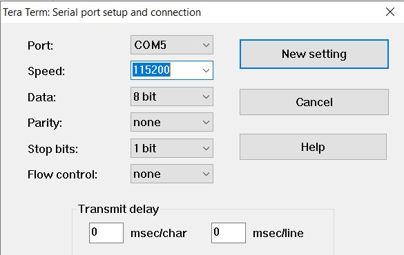
- Go to “Setup” -> Click on “Serial port…” and set the Speed=115200, Data=8 bits, Parity=none, Stop bits=1 bit. Press “New Setting” to save these changes.
- Go to “Setup” -> Click on “Terminal…” and make sure “Local Echo” is checked so that you can see the commands you will be typing.
- Enter the following AT commands shown in bold letters. Below you can also see a brief description and the response of each AT command. The following configurations are based on TELUS as the current carrier. If your carrier requires a different configuration, modify the AT commands accordingly. For full description of AT commands, see Quectel_BG96_AT_Commands_Manual[13].
ATI // Display Product Identification Information
Quectel
BG96
Revision: BG96MAR02A07M1G
OK
AT GSN // Request International Mobile Equipment Identity (IMEI). Note that IMEI is a unique 15-digit identification or serial number of the module.
866425033446404
OK
AT CFUN=1 // Set Phone Functionality as Full
OK
AT QCCID // Show the SIM card’s Integrated Circuit Card Identifier (ICCID) number
QCCID: 8912230100074759513F
OK
AT COPS=0 // Automatic Operator selection
OK
AT QCFG=”NWSCANSEQ”,020301 // Configure Radio Access Technologies (RAT) searching sequence
02: LTE-M
03: NB-IoT
01: GSM
OK
AT QCFG=”IOTOPMODE”,0 // Configure network category to be searched under LTE RAT.
0: LTE Cat M1
1: LTE Cat NB1
2: LTE Cat M1 and Cat NB1
OK
AT QCFG=”BAND”,0,80A,80A // Band configuration. Specify the frequency bands allowed to be searched of User Equipment (UE). The hex number represent the GSM, LTE-M and NB-IoT band values, respectively.
0: not to change frequency band.
80A : LTE B2 LTE B4 LTE B12
OK
AT CSQ // Signal quality report. Indicate the received signal strength indicator (RSSI) and the channel bit error rate (BER). For example the first received number (23) means the RSSI is -67 dBm and the second number (99) shows the channel bit error rate in percent.
0: Less than or equal to -113dBm
1: -111dBm
2…30: -109… -53dBm
31: Greater than or equal to -51dBm
99: Not known
CSQ: 23,99
OK
AT COPS=? // Operator Status.
0: Unknown
1: Available
2: Current operator
3: Forbidden
As you see in the response from the module the status for TELUS is 2 which means it is the current operator.
COPS: (1,”Bell”,”Bell”,”302610″,8),(1,”Rogers Wireless”,”ROGERS”,”302720″,8),(1,”Rogers Wireless”,”ROGERS”,”302720″,0),(2,”TELUS”,”TELUS”,”302220″,8),,(0,1,2,3,4),(0,1,2)
OK
G. GPS test using AT commands
- Enter the following simple AT commands to enable the GPS and acquire location information. For a complete set of Global Navigation Satellite System (GNSS) commands see BG96 GNSS AT Commands Manual[14].
| AT QGPS=1 // Turn on GNSS
OK AT QGPSLOC? // Acquire positioning information QGPSLOC: 012102.0,4919.1986N,12305.5925W,3.2,-19.0,2,177.06,0.0,0.0,230220,08 OK AT QGPSEND // Turn off GNSS OK |
Note: If you are running the lab in a building, after you enter AT QGPSLOC?, you may get “ CME ERROR: 516”. This error means the modem has not received a GPS fix yet. You can wait for a few more minutes or move the GPS antenna near a window or outside. Note that a GPS fix is the locational information that the GPS system provides for a specific point.
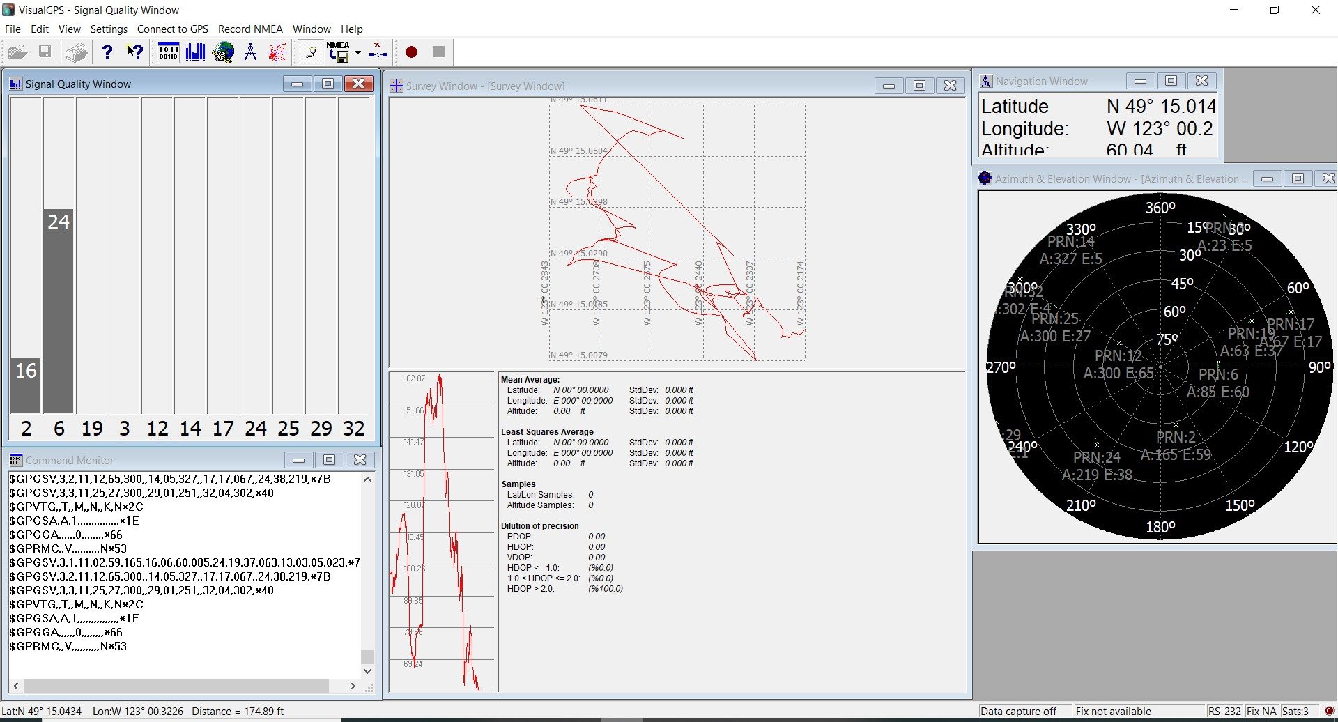
- In order to test the GNSS commands using NMEA USB port, download VisualGPS[15]. Note that NMEA is a standard data format that is supported by GPS manufacturers. Run the VisualGPS application and go to “Connect to GPS” -> Click on “Connect using serial port” to graphically display the location.
- Choose “Quectel USB NMEA Port”, set the baud rate=115200 and press “Ok”. As it is shown in Figure2.12, you will see the GPS data such as latitude, longitude, attitude, signal quality and etc.
H. SMS text messaging
If your carrier connectivity subscription includes SMS text messaging you will be able to send a text message using AT commands.
- Enter the following commands:
| AT CMGF=1 // SMS message format is set as text
OK AT CSCS=“GSM” // Character set is GSM OK AT CMGS=“12369912020” // Destination phone number > Hello, this is a test. // Enter your message and then press CTR-Z to send CMGS: 5 // Message reference upon successful delivery OK |
- http://cloudconnectkits.org/product/telus-lte-m-iot-starter-kit ↵
- https://www.quectel.com/product/bg96.htm ↵
- https://os.mbed.com/components/X-NUCLEO-IKS01A2/ ↵
- https://www.st.com/en/mems-and-sensors/lsm6dsl.html ↵
- https://www.st.com/en/mems-and-sensors/lsm303agr.html ↵
- https://www.st.com/content/st_com/en/products/mems-and-sensors/pressure-sensors/lps22hb.html ↵
- https://www.st.com/content/st_com/en/products/mems-and-sensors/pressure-sensors/lps22hb.html ↵
- https://os.mbed.com/platforms/ST-Nucleo-L496ZG/ ↵
- http://cloudconnectkits.org/product/telus-lte-m-iot-starter-kit ↵
- https://telus.jasperwireless.com/provision/jsp/login.jsp ↵
- https://github.com/pengphei/quectel-ec20/tree/master/drv/Quectel_LTE_Windows_USB_Driver_V1.0 ↵
- https://www.quectel.com/UploadImage/Downlad/Quectel_BG96_AT_Commands_Manual_V2.1.pdf ↵
- https://www.quectel.com/UploadImage/Downlad/Quectel_BG96_AT_Commands_Manual_V2.1.pdf ↵
- https://www.quectel.com/UploadImage/Downlad/Quectel_BG96_GNSS_AT_Commands_Manual_V1.1.pdf ↵
- http://www.visualgps.net/#visualgps-content ↵
