Chapter 3: TCP/IP AT Commands
3.1 Introduction
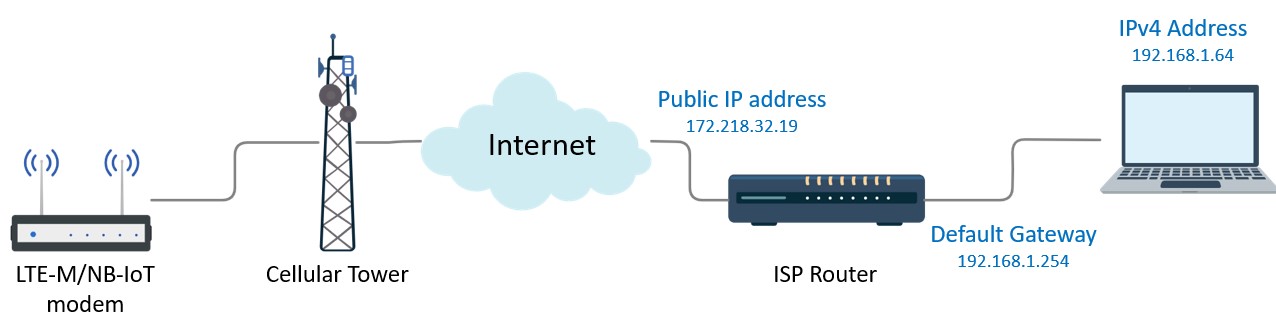
In this chapter, we would like to connect the BG96 board to the Internet to send and receive data. For this purpose, the BG96 board needs to establish a TCP/IP connection to a server. This can be done by using a software program such as SocketTest to enable the computer to act as a server. The configuration used in this lab is shown in Figure3.1.
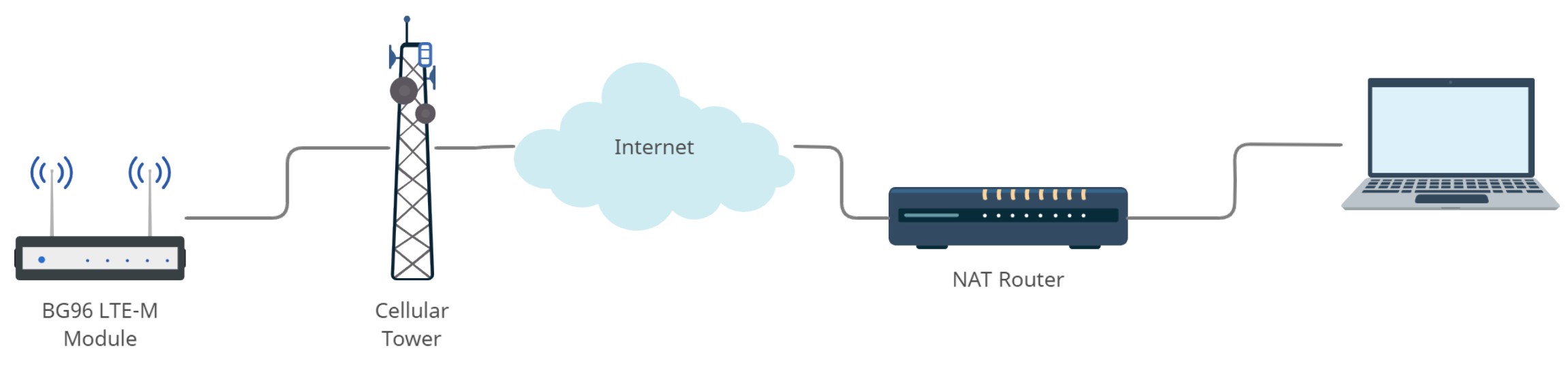
For the BG96 board to communicate with the server installed on the computer, the BG96 board sends the data to the IP address of the computer. If the computer is installed behind a Network Address Translation (NAT) router like the ones in most homes and offices, the computer may use an internal address. For proper communication to take place, the NAT router needs to work well and proper port forwarding needs to be configured.
Quectel BG96 module can access to the Internet using the embedded TCP/IP stack and AT Commands. The module supports services for UDP client/server and TCP client/server. In this lab, the BG96 module will act as a TCP client and connects to a TCP server to exchange data.
3.2 Practical tasks
To start using TCP/IP AT Commands, first you need to configure the parameters of the context such as the APN, username, and password. Second, the Packet Data Protocol (PDP) context which is is the connection between the modem and the end address is activated. Third, you will start a socket service to exchange data. Finally the socket service is closed and PDP context is deactivated.
A. Configure your PC as TCP/IP server
In this part of the lab, you will set up a TCP/IP server on your computer to be able to communicate with the BG96 module.
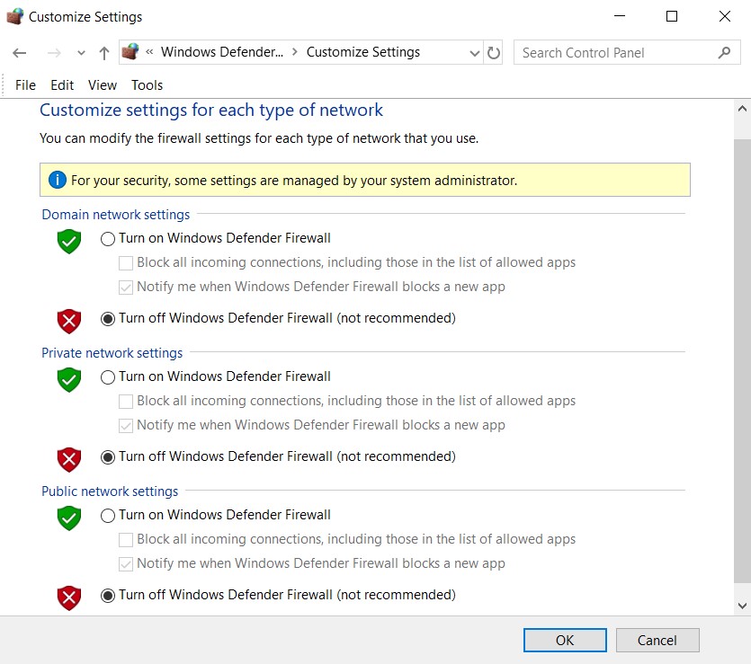
- Go to “Control panel”->”Windows Defender Firewall”. Click on “Turn Windows Defender Firewall on or off” and turn off Windows Firewall or any third party firewall such Norton’s or hardware firewall.
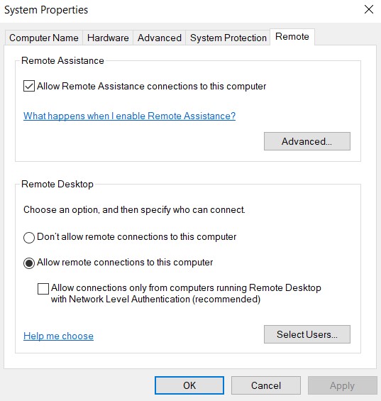
- To allow remote access to your PC, go to “Control Panel” -> “System”->”Remote settings”. In the “Remote” tab select “Allow remote connections to this computer”.
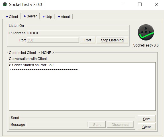
- To create a TCP/IP server, download and run SocketTest[1]. Click on “Server” tab and enter a number (e.g., 350) as your port number. Click “Start Listening”.
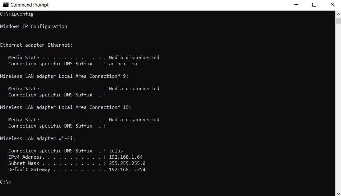
- In order to obtain the IP address of your computer and the default gateway, press Windows R to open “Run” box. Type “cmd” and then click “OK” to open a Command Prompt.
- In Command Prompt type “ipconfig” to get the IPv4 Address and Default Gateway (i.e., the IP address of the router) in the form of xxx.xxx.xxx.xxx. In our example as it shown below “IPv4 Address = 192.168.1.64” and “Default Gateway = 192.168.1.254”
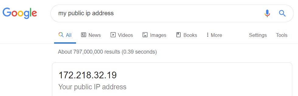
- Go to “Google” and search for “my public IP address”. This is the IP address of your ISP router available to the rest of the Internet. Alternatively, you can go to https://canyouseeme.org/ and find your public IP address.
The Default Gateway is the IP address of the interface of your ISP router connected to your PC. IPv4 address is the private IP address given to your PC by the router. Since the private IP address is not addressable from outside your network, using “port forwarding”, you can tell your router where to direct traffic for a specific port on your PC. In other words, port forwarding allows a remote computer on a different network (e.g., BG96 module) to connect to your PC on a private network and run a service behind the router.
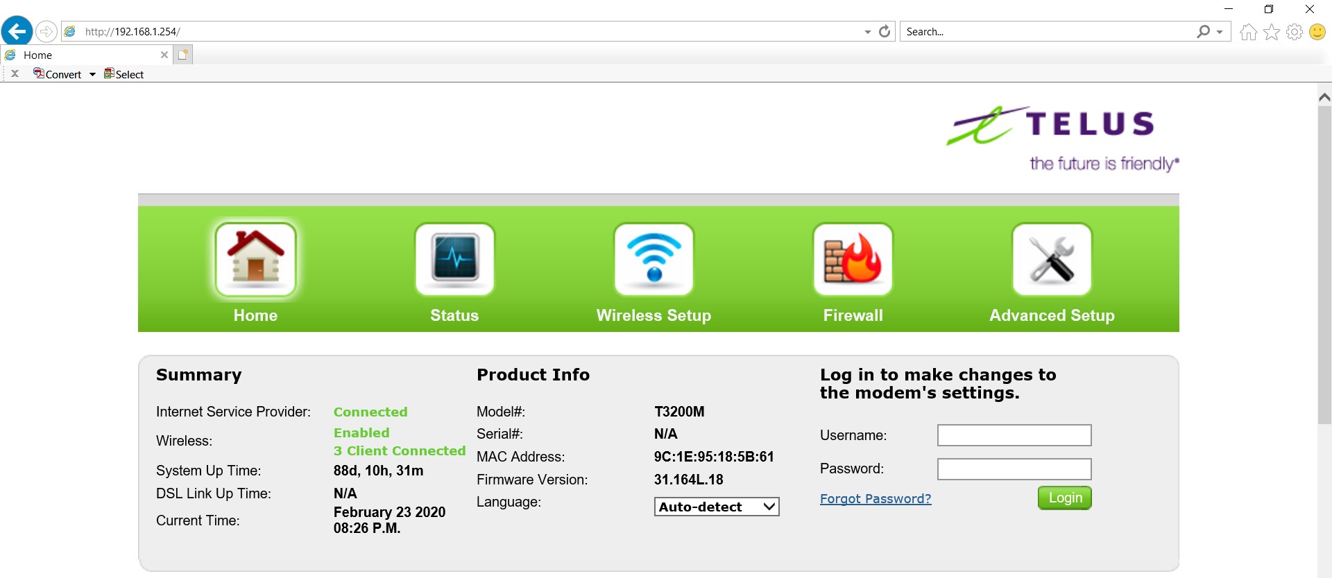
- Go to your internet browser and in the address bar type in the “Default Gateway” which was 192.168.1.254 in our example. You may also find the Default Gateway address on your WiFi-Router security tag. Enter the Username/Password for your router to log in. Note that depending on your router you may see a different interface.
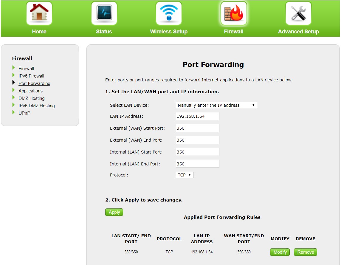
- To make the service port available to the Internet, you need to set up port forwarding using the IPv4 address (192.168.1.64) and Port number (350) in your router so that your ISP does not block the port as shown in Figure3.9.
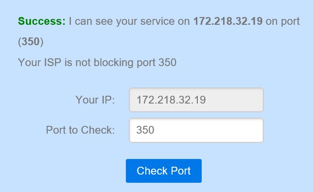
- To verify that the port is open and your ISP does not block it, go to www.canyouseeme.org, enter your public IP address and port number and click “Check Port”. Make sure the server you created in SocketTest is listening at that port; otherwise, you will see that the port is closed as shown in Figure3.10.
B. Configure BG96 module as TCP/IP client
In this part of the lab, you will set up a TCP client connection to enter into buffer access mode. BG96 TCP/IP AT Commands Manual[2] has the full list and description of different modes and commands required for TCP/IP connections.
- Open “Tera Term” and use the APN provided by the SIM carrier (e.g., m2m-west.telus.iot) to configure a context via AT Commands.
| AT QICSGP=1,1,”M2M-WEST.TELUS.IOT”,””,””,1 // Set the your mobile carrier APN
OK |
- Activate the context and query the state of the context and IP address of the module. AT QIDEACT=1 can be used to deactivate a context.
| AT QIACT=1 // Activate a context
OK
AT QIACT? // query the context state QIACT: 1,1,1,”10.200.109.166″ OK |
- Set up a TCP client connection using your PC public IP address (e.g., 172.218.32.19) and port number (e.g., 350). If the connection is successful “ QIOPEN: 0,0” will be returned and SocketTest will show the new client IP address.
| AT QIOPEN=1,0,”TCP”,”172.218.32.19″,350,0,0 // Set up a TCP client connection using your own public IP address
OK
QIOPEN: 0,0 |
C. Send and receive data using BG96 module
- Enter the AT Command below and type in your text. Then press CTR Z to send it. The received text should be shown on SocketTest.
| AT QISEND=0 // Send changeable length data. After text press CTR Z to send.
> Hello, this is a test SEND OK |
- When you reply using SocketTest, the module will show QIURC: “recv”,0 which means a message has been received in the buffer. To read the buffer, type in AT QIRD=0,1500.
| QIURC: “recv”,0 // Send changeable length data. After text press CTR Z to send.
AT QIRD=0,1500 QIRD: 30 Hi, I received your message.
OK |
- Close the connection using AT QICLOSE=0.
The instructions above explained how to establish a TCP client connection using the BG96 module. If you are interested, referring to BG96 TCP/IP AT Commands Manual[3] you can try establishing UDP client, TCP server and UDP server connections.
D. Connectivity to the Internet
To check the connectivity between BG96 board and the Internet, we send ping commands. Since ping uses TCP/IP connection, the success of the command below shows that your board is capable of making TCP/IP connection and you can check the connectivity.
AT QPING=1, “www.bcit.ca”
