Chapter 9. SD-WAN
9.1 SD-WAN
Learning Objectives
- Create a Demo of SDWAN
- Configure SDWAN features
Scenario: Software-defined wide-area network (SD-WAN) solutions transform an organization’s capabilities by leveraging the corporate wide-area network (WAN) as well as multi-cloud connectivity to deliver high-speed application performance at the WAN edge of branch sites. One of the chief benefits of SD-WAN is that it provides a dynamic path selection among connectivity options—MPLS, 4G/5G, or broadband—ensuring organizations can quickly and easily access business-critical cloud applications.SD-WAN Document Library. In this scenario, we are simulating SD-WAN by using OpenWrt and this allows you to play with the features of SD-WAN. Port 4 and Port 5 acts like your different connection and you can manage them through SD-WAN.
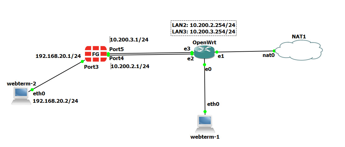
| Device | IP address |
|---|---|
| WebTerm1 (WRT Manager) | 192.168.1.2/24 |
| WebTerm2 (Firewall Manager) | 192.168.20.2/24, GW: 192.168.20.1, DNS: 4.2.2.4 |
| FortiGate | Port 3: 192.168.20.1/24
Port 4: 10.200.2.1/24 Port 5: 10.200.3.1/24 |
| OpenWrt | Eth0: connected to WRT Manager
Eth1: connected to NAT Eth2: 10.200.2.254/24 Eth3: 10.200.3.254/24 |
| NAT |
Configure OpenWrt
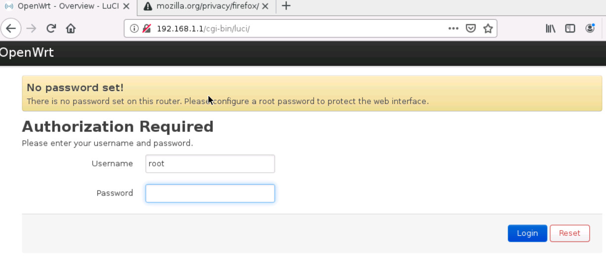
To configure OpenWrt, you should connect through port eth0. By default, the IP address of eth0 is 192.168.1.1/24. So, you can set the WRTManager as 192.168.1.2/24 and connect to OpenWrt through the web browser. You can type in the browser: http://192.168.1.1, and click on “Login” without entering any password.
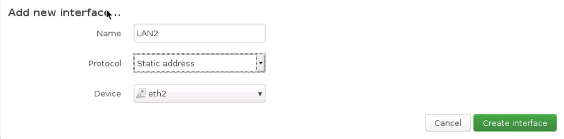
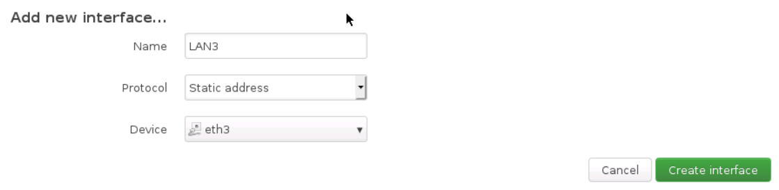
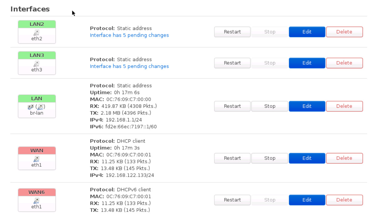
Then, go to network > interfaces > Add new interface …
And Enter the following information:
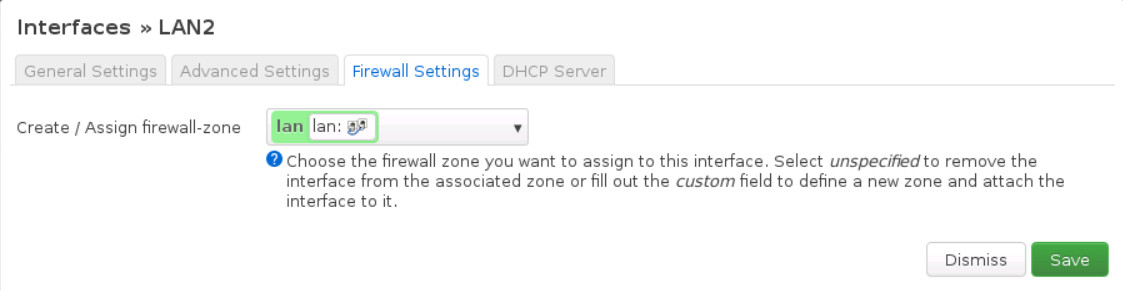
- Name of Interface: LAN2
- Cover the following interface: eth2
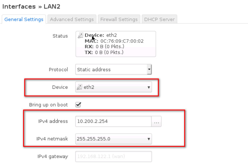
- Then, submit and add IPV4: 10.200.2.254, netmask: 255.255.255.0
- And finally, under Firewall Settings select firewall-zone as Lan
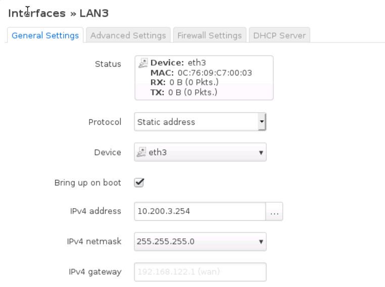
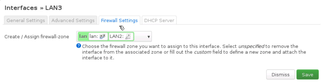
- Name of Interface: LAN3
- Cover the following interface: eth3
- Then, submit and add IPv4: 10.200.3.254 netmask: 255.255.255.0
- And finally, under Firewall Settings select firewall-zone as Lan
Your interfaces in OpenWrt should be like Figure 9.9:
Firewall Configuration
- Set the port3 as a management port and connect it to Firewall Manager (WebTerm2).
FGVM01TM19008000 # config system interface
FGVM01TM19008000 (interface) # edit port3
FGVM01TM19008000 (port3) # set ip 192.168.20.1/24
FGVM01TM19008000 (port3) # set allowaccess http https
FGVM01TM19008000 (port3) # end
- Go to Firewall > Network > Interfaces > port4. Set Name as WAN2 and IPv4 as 10.200.2.1/24.
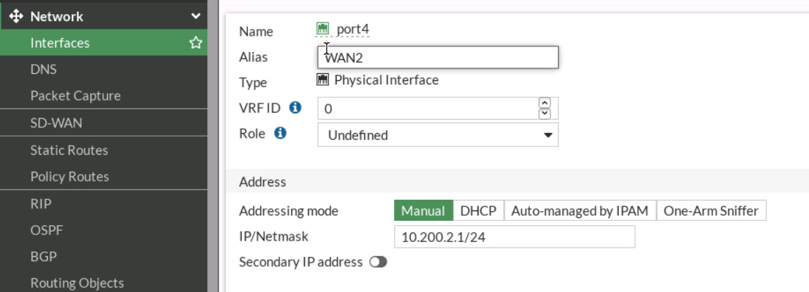
Figure 9.10: Port4 configuration - Go to Firewall > Network > Interfaces > port 5. Set Name as WAN3 and IPv4 as 10.200.3.1/24.
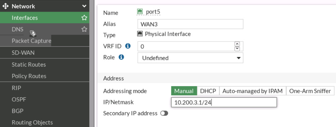
Figure 9.11: Port5 configuration - Go to Network > SD-WAN > Select Interface Port4. Gateway: 10.200.2.254.
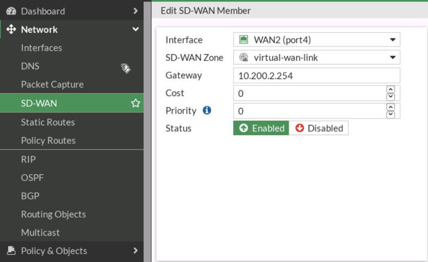
Figure 9.12: Add port4 as SD-WAN members - Add SD-WAN > Select Interface Port5. Gateway: 10.200.3.254.
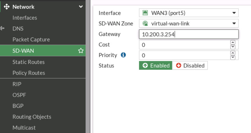
Figure 9.13: Add port5 as SD-WAN members 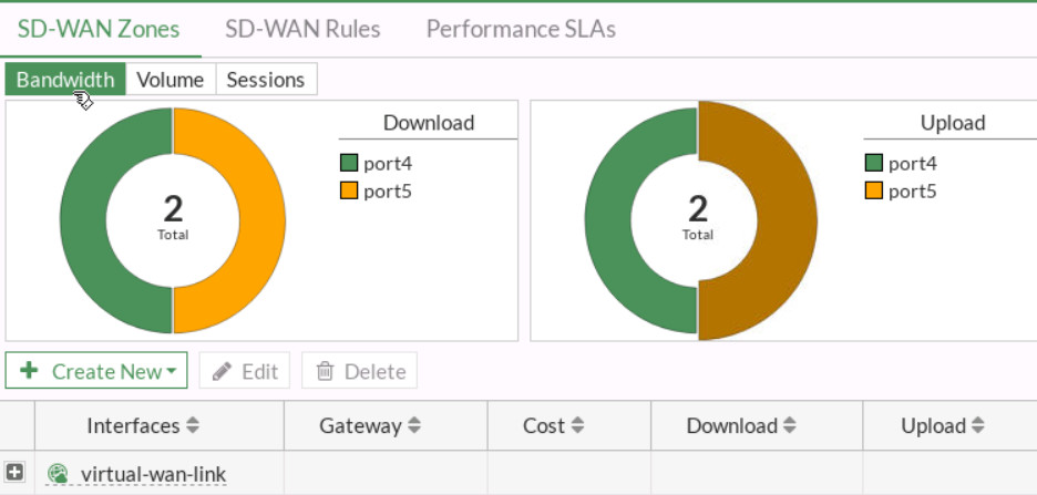
Figure 9.14: SD-WAN Zones - Create a static route as Figure 9.15.
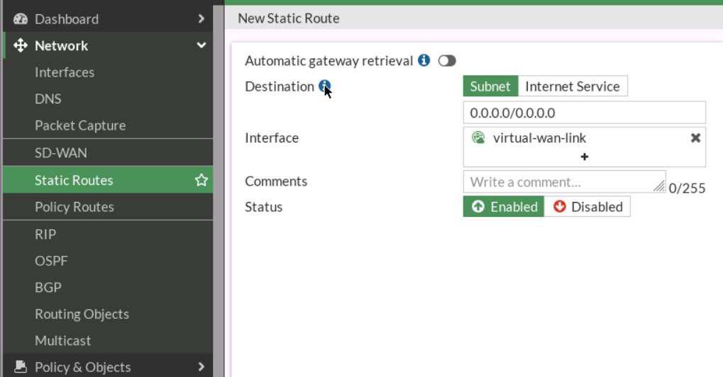
Figure 9.15: Create a static route to SD-WAN - Create a firewall policy as following table:
Table 9.2: Firewall Policy configuration Field Value Name SDWAN Incoming Interface LAN (PORT3) Outgoing Interface SD-WAN Source ALL Destination ALL Schedule Always Service ALL 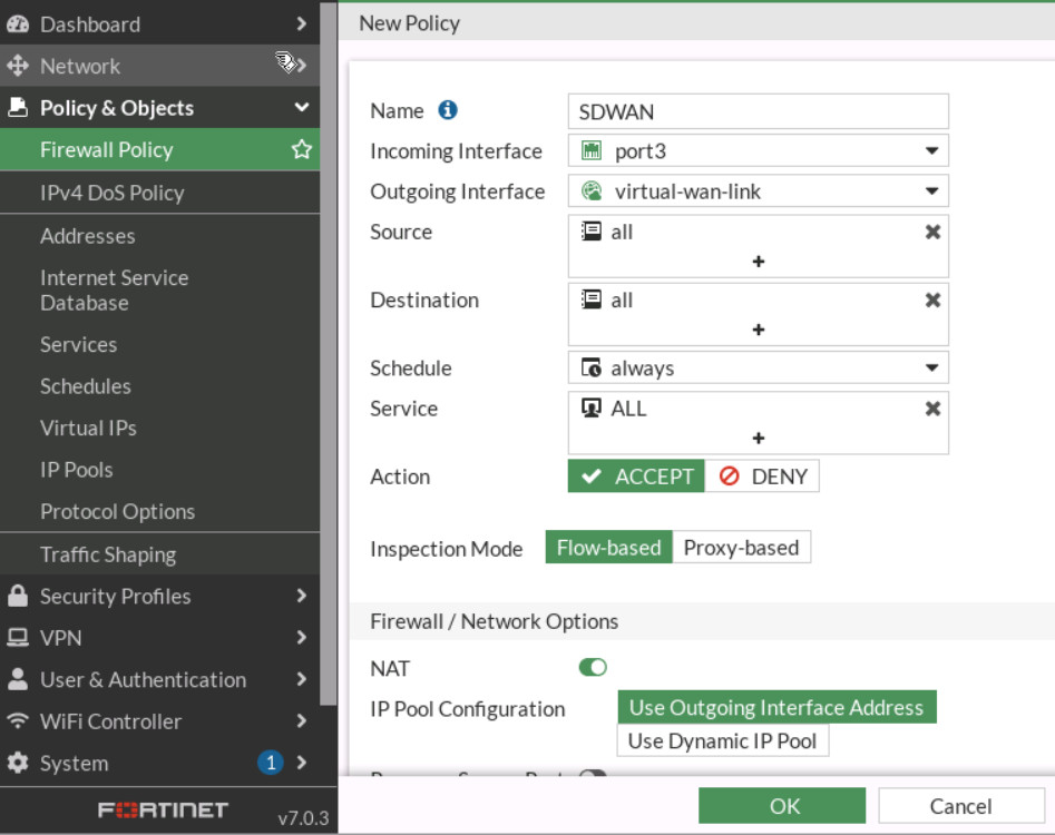
Figure 9.16: Create a Firewall Policy - Go to Network > SD-WAN Rule, create a rule as follows:
- Name: MyRule
- Source Address: All
- Destination Address: All
- Protocol Number: Any
- Strategy: Best Quality
- Interface Preference: Port 4, Port 5
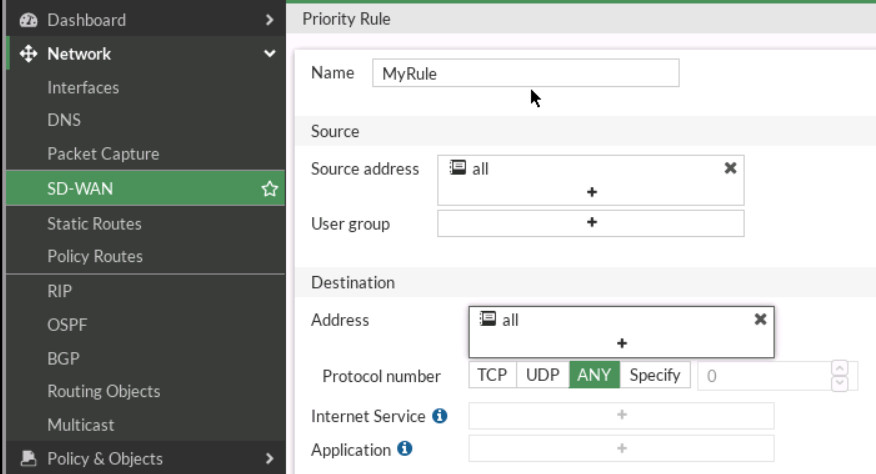
Figure 9.17: Priority Rule - Measured SLA. Create a SLA:
- Name: MySLA
- Protocol: Ping
- Server: 4.2.2.4
- Add Target and leave the default parameters
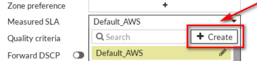
Figure 9.18: Add target 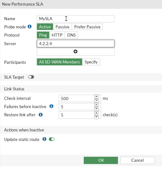
Figure 9.19: Create a SLA 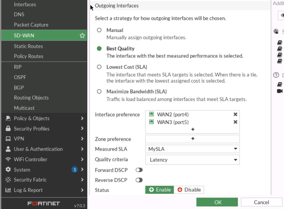
Figure 9.20: SD-WAN Configuration - Go to Network > SD-WAN and verify your SD-WAN Usage.
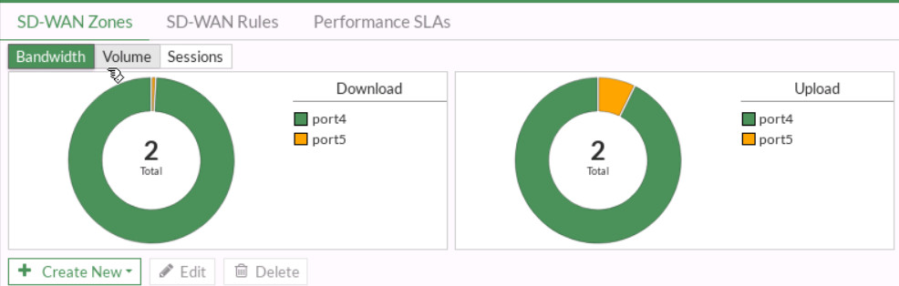
Figure 9.21: SD-WAN usage - Now, go to GN3 and disconnect port4. You should be able to reach the Internet from Firewall Manager.
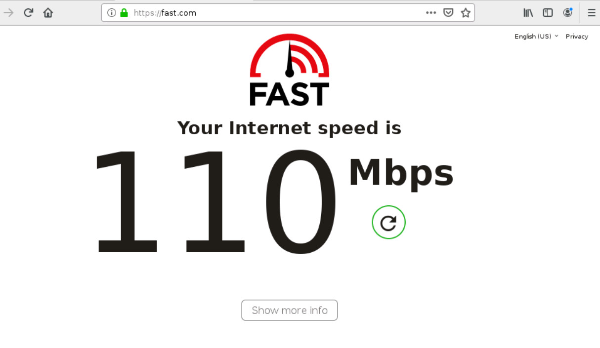
Figure 9.22: Verify configuration - Go to Network > SD-WAN and verify your SD-WAN Usage.
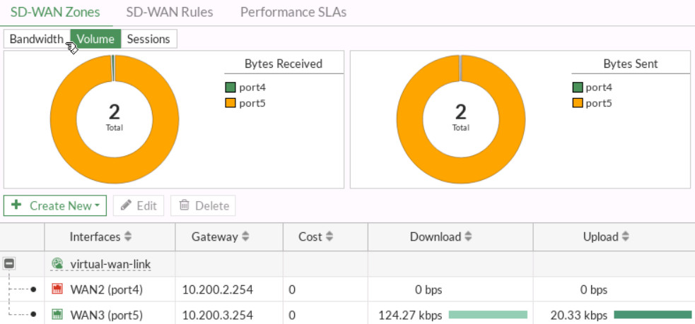
Figure 9.23: Status of interfaces - Open the browser in the Firewall Manager and type google.com or any websites and then go to the Dashboard > FortiView Sessions. Verify your result.
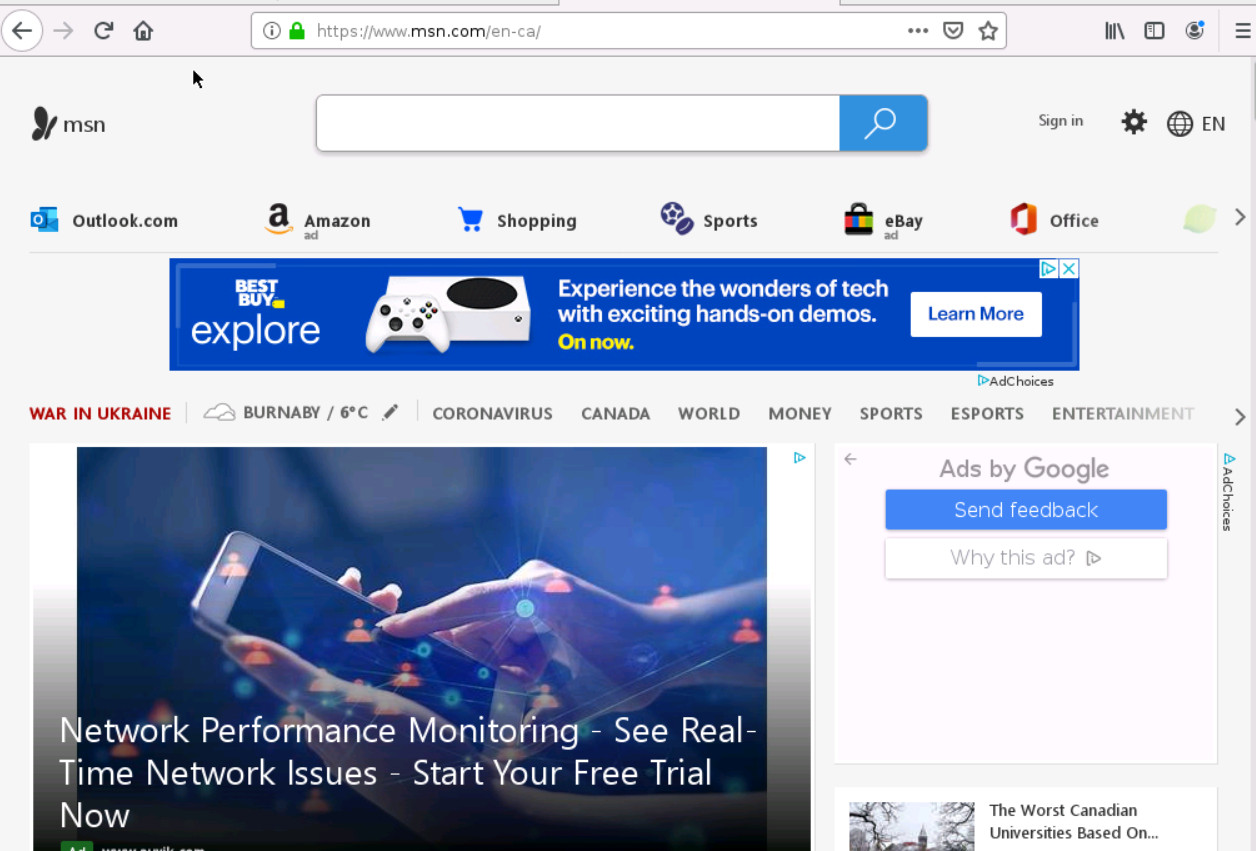
Figure 9.24: Verify configuration 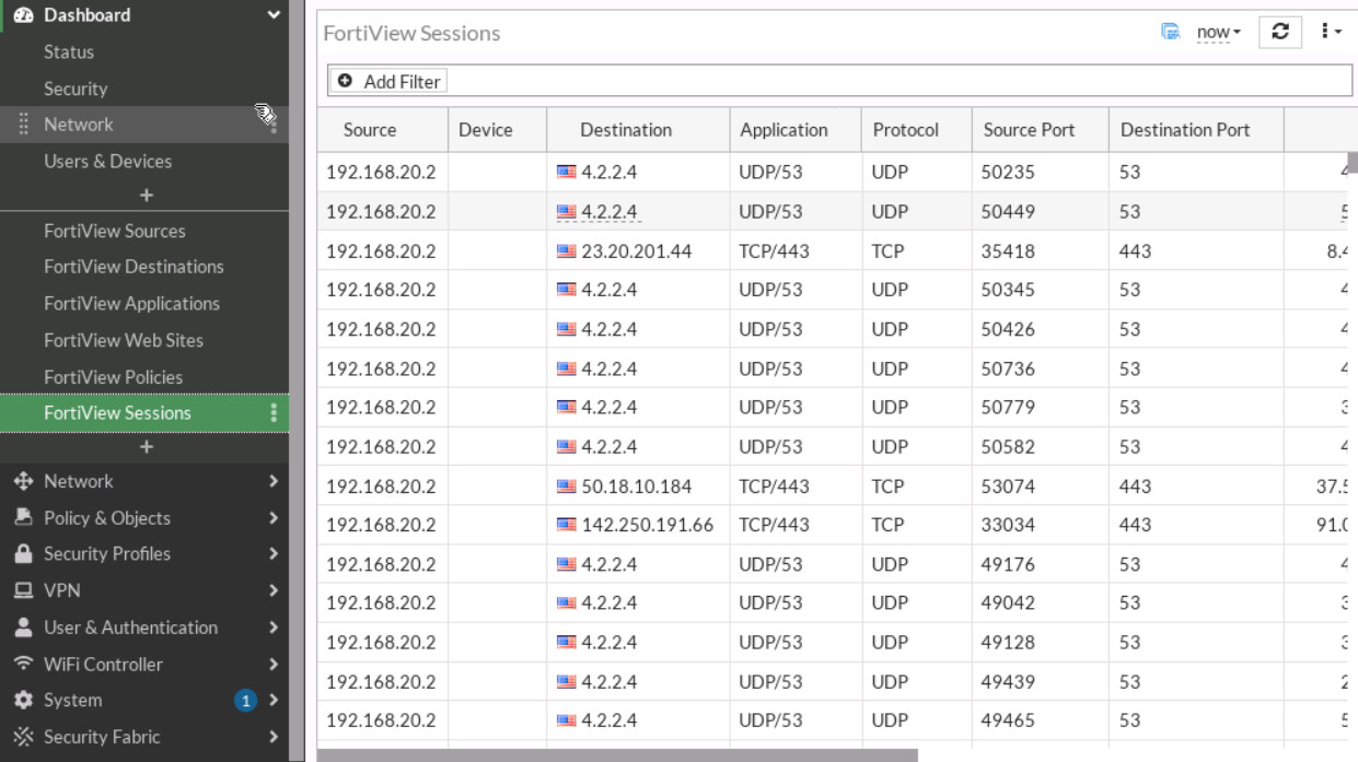
Figure 9.25: FortiView Sessions - Go to Log & Report > Event > SD-WAN Event. Verify your result.
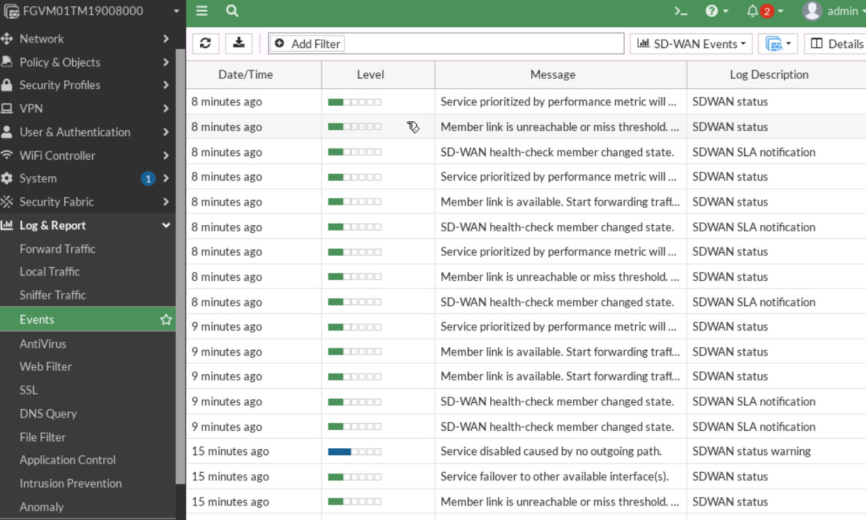
Figure 9.26: SD-WAN Events
