Chapter 4. VPN
4.1 IPsec VPN
Learning Objectives
- Configure an IPsec VPN
- Configure a site-to-site VPN
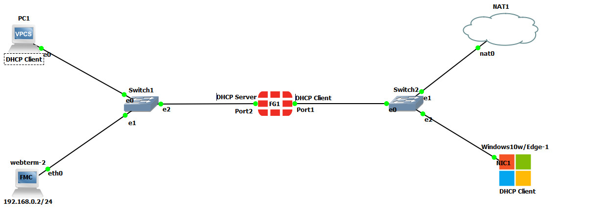
Scenario: We are going to have IPsec VPN from Windows to FortiGate Firewall. First, we are going to install FortiClient on Windows and then we will configure the firewall for FortiClient. The goal of this scenario is to have connectivity from Windows to PC1. You should be able to ping PC1 after you have established your VPN connection.
Configuration
| Device | IP address | Access |
|---|---|---|
| WebTerm2 | 192.168.0.2/24 | – |
| VPC | DHCP Client | – |
| Ethernet Switch1-2 | – | – |
| FortiGate | Port 1: DHCP Client
Port 2: 192.168.0.1/24 DHCP Server (192.168.0.10 to 192.168.0.20) |
ICMP
HTTP HTTPS |
| Windows | DHCP Client | – |
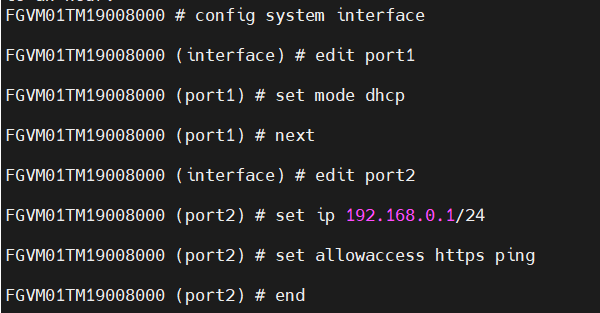
Figure 4.2: Basic configuration of port1 and port2
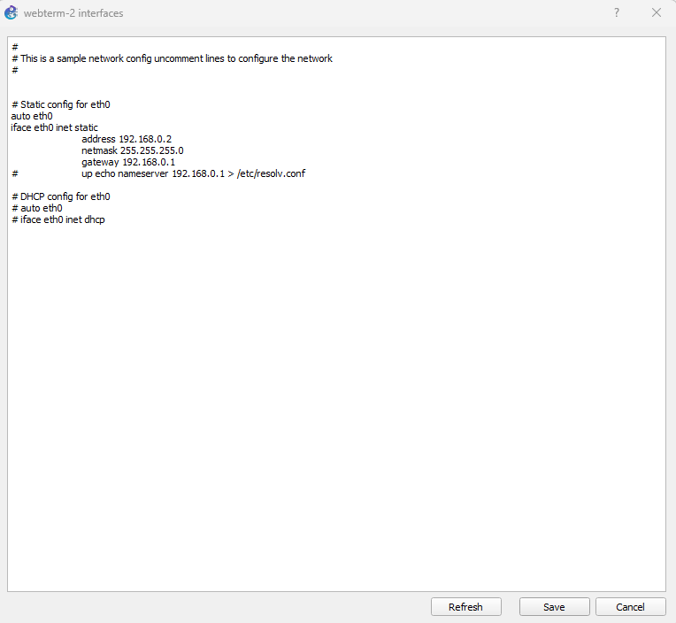
Figure 4.3: Configure static IP address on Webterm2
After configuring Port 2, you should be able to access the firewall via WebTerm2. Open a browser and enter: https://192.168.0.1
- Set a DHCP server on interface port2 (Range of IP address should be: 192.168.0.20 to 192.168.0.30, DNS: 4.2.2.4).
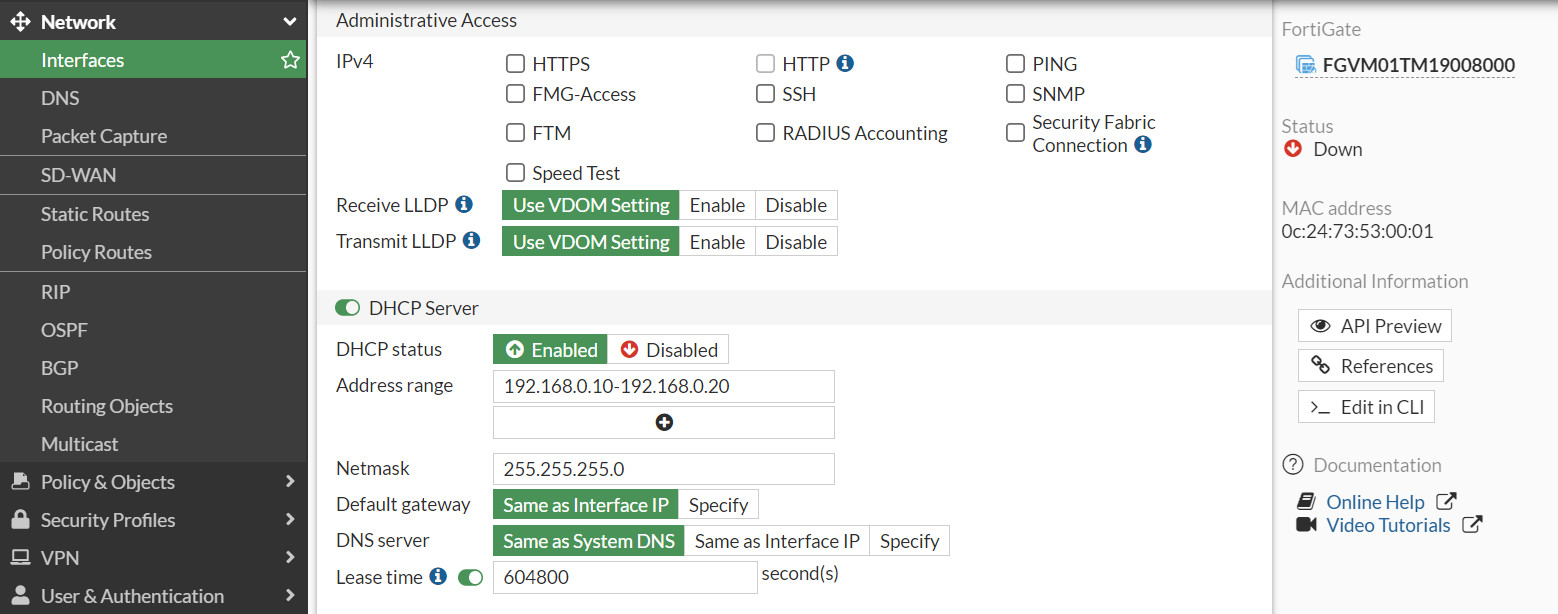
Figure 4.4: Set DHCP IP address 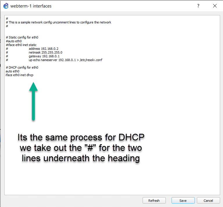
Figure 4.5: Enable DHCP client - Go to User & Authentication > User Group > Create New:
- Name: VPN_GRP_A0ID
- TYPE: Firewall
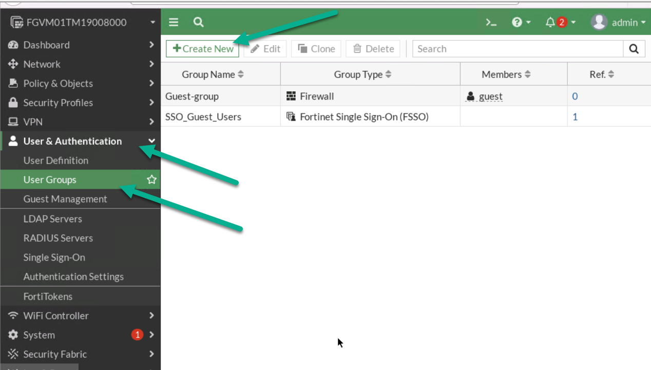
Figure 4.7: Create a user group 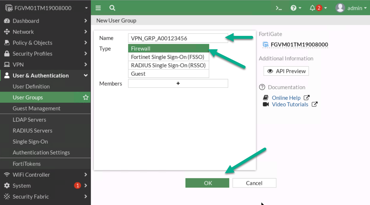
Figure 4.8: Create a group in the firewall - Go to User & Authentication > User Definition > Create a User:
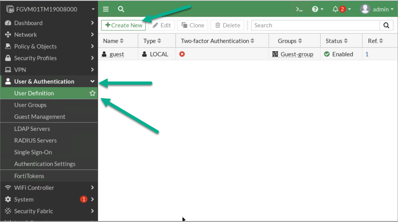
Figure 4.9: Create a new user 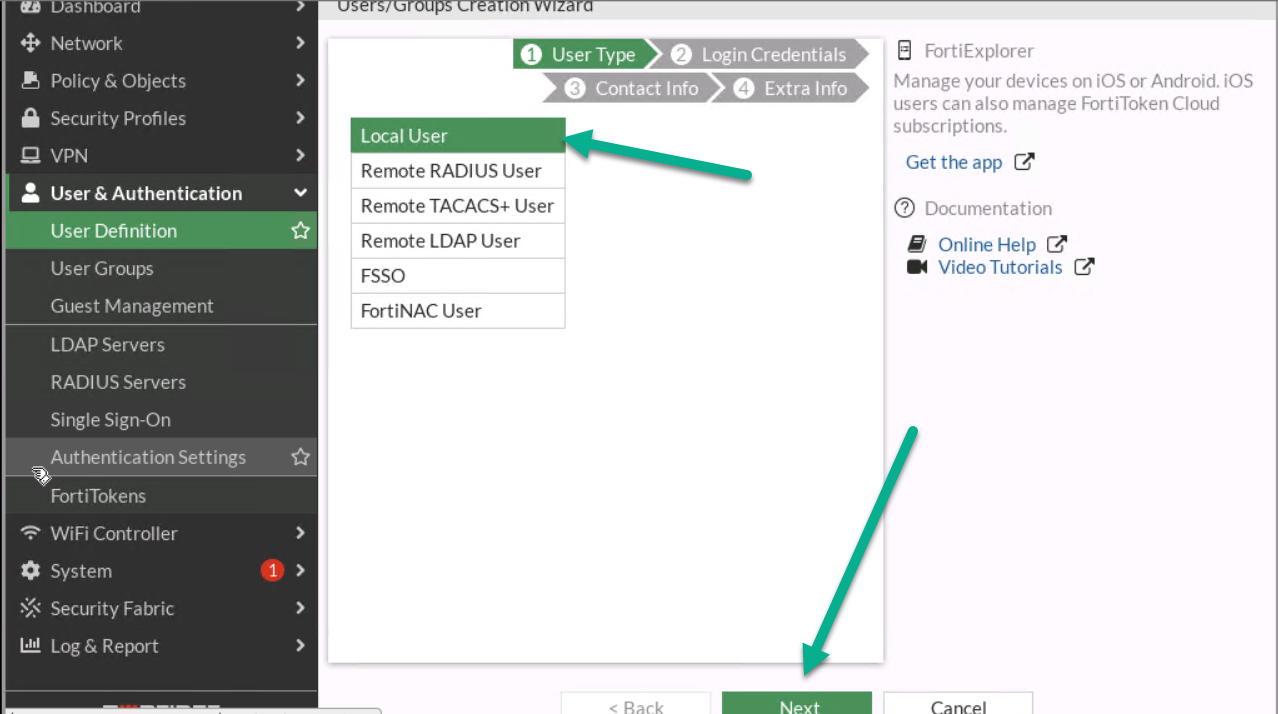
Figure 4.10: Create a local user 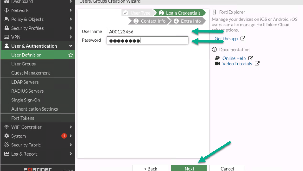
Figure 4.11: Configure login credentials for the user 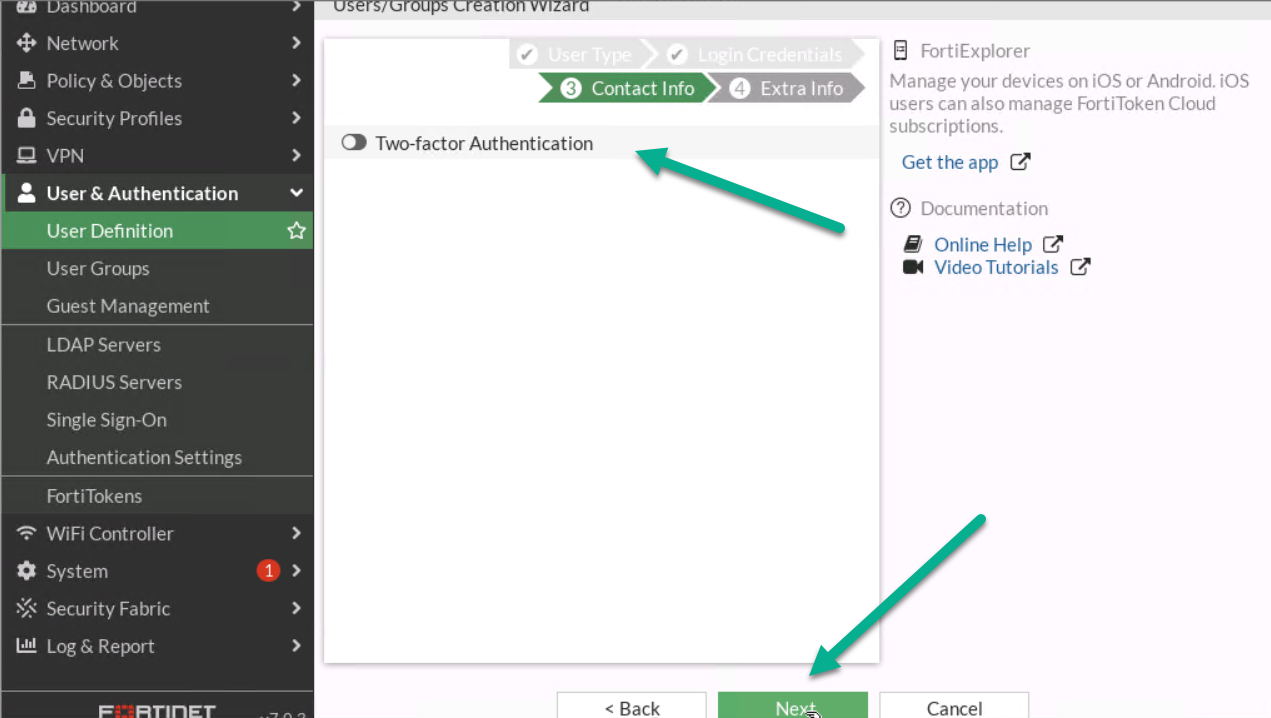
Figure 4.12: Contact info - Assign User Group to your profile.
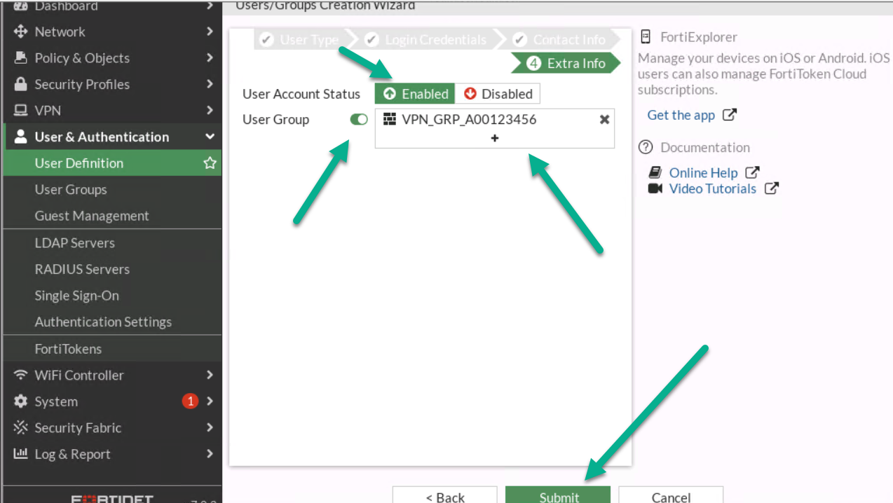
Figure 4.13: Assign a user to the group 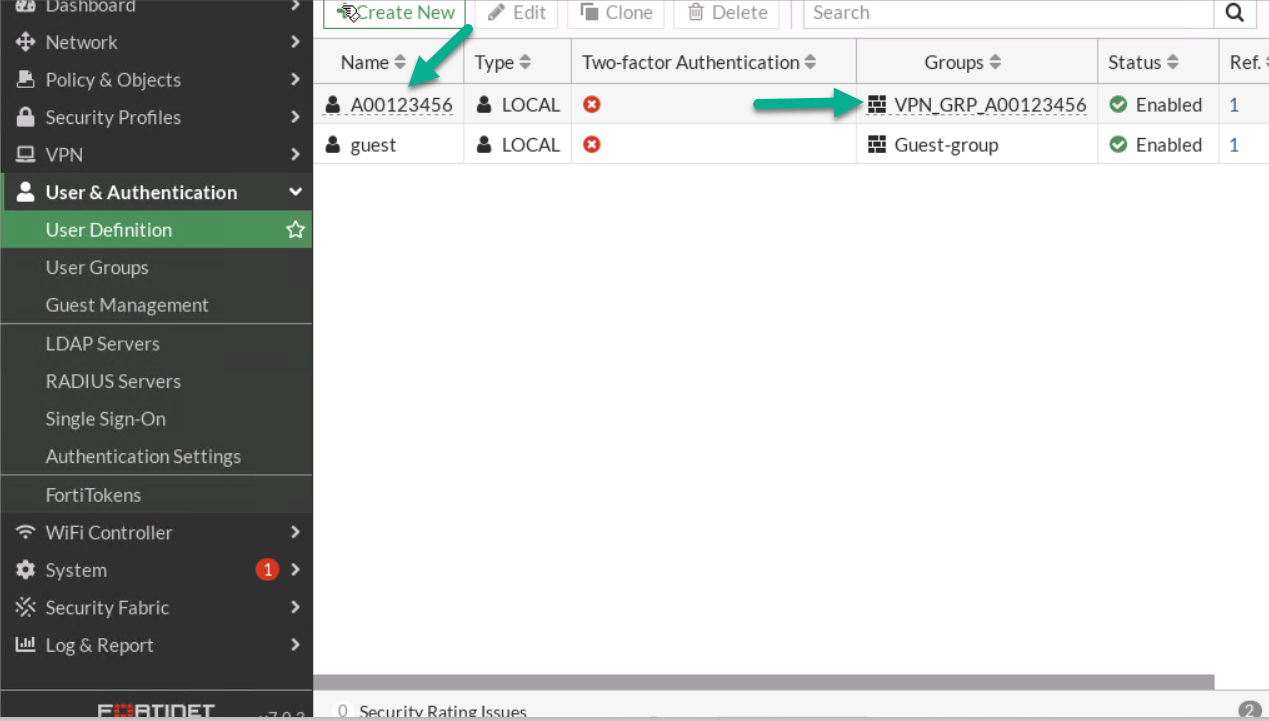
Figure 4.14: Verify configuration - Go to VPN > IPsec Wizard.
- First:
- Select Name: A0ID- VPN(A0ID is a student ID)
- Template Type: Remote Access
- Remote Type Device: FortiClient
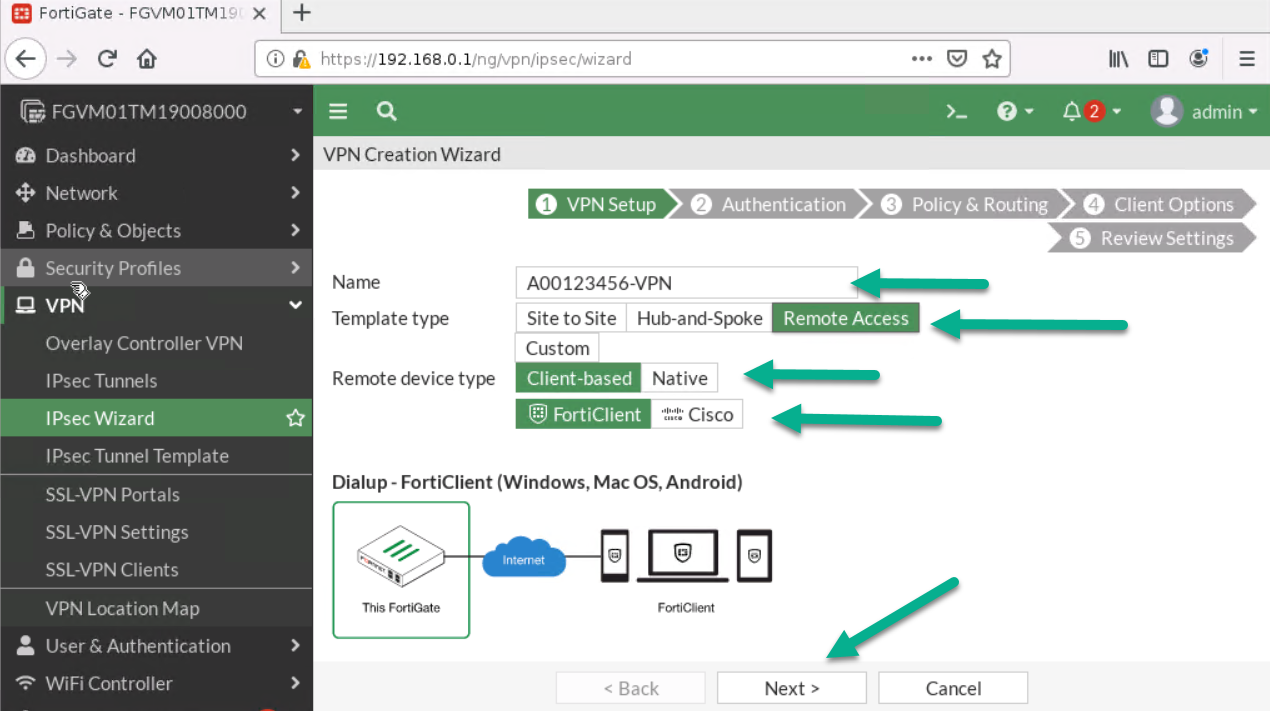
Figure 4.15: Create a VPN connection - Then:
- Incoming Interface: Port1
- Pre-shared Key: <Select a key like a password>
- User Group: VPN_GRP_A0ID
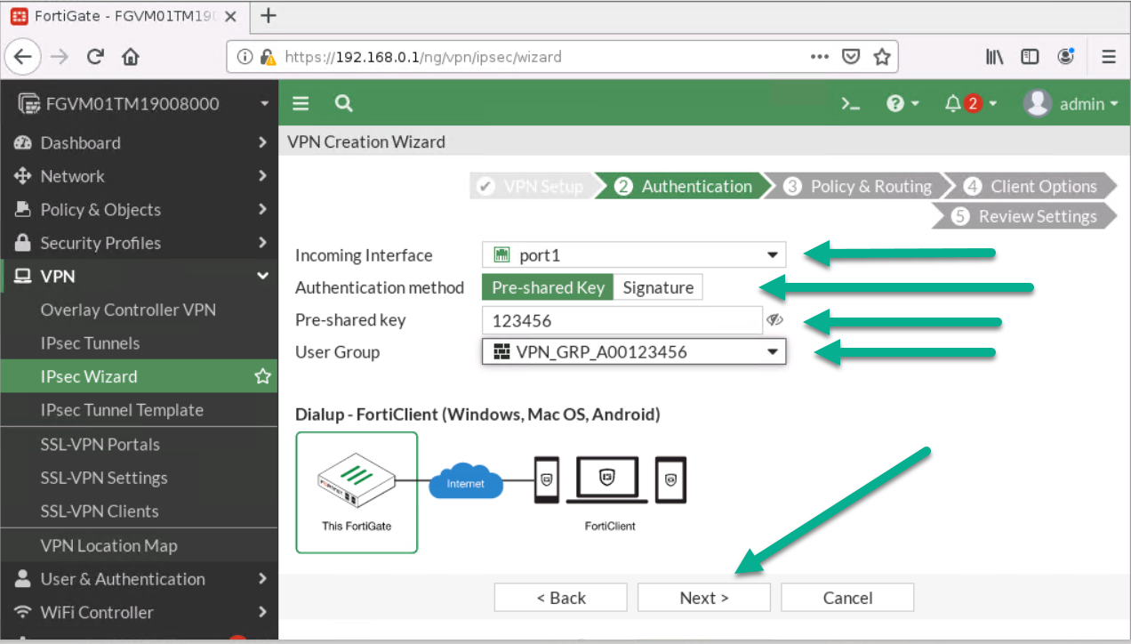
Figure 4.16: Configure authentication - Next:
- Local Interface: Port 2
- Local Address: Add your local range of IP address (192.168.0.0/24)
- Client Range: 172.16.0.1 to 172.16.0.10
- Subnet Mask: 255.255.255.0
- Disable Split Tunneling
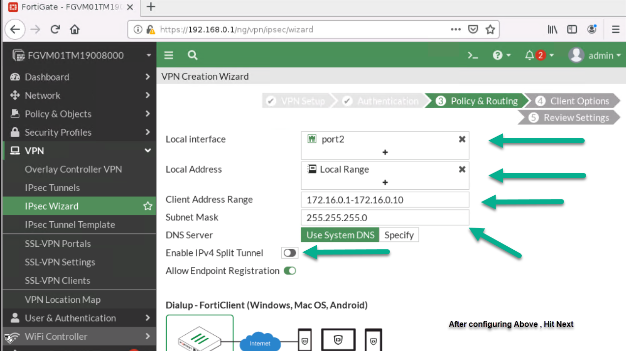
Figure 4.17: Configure Policy & Routing 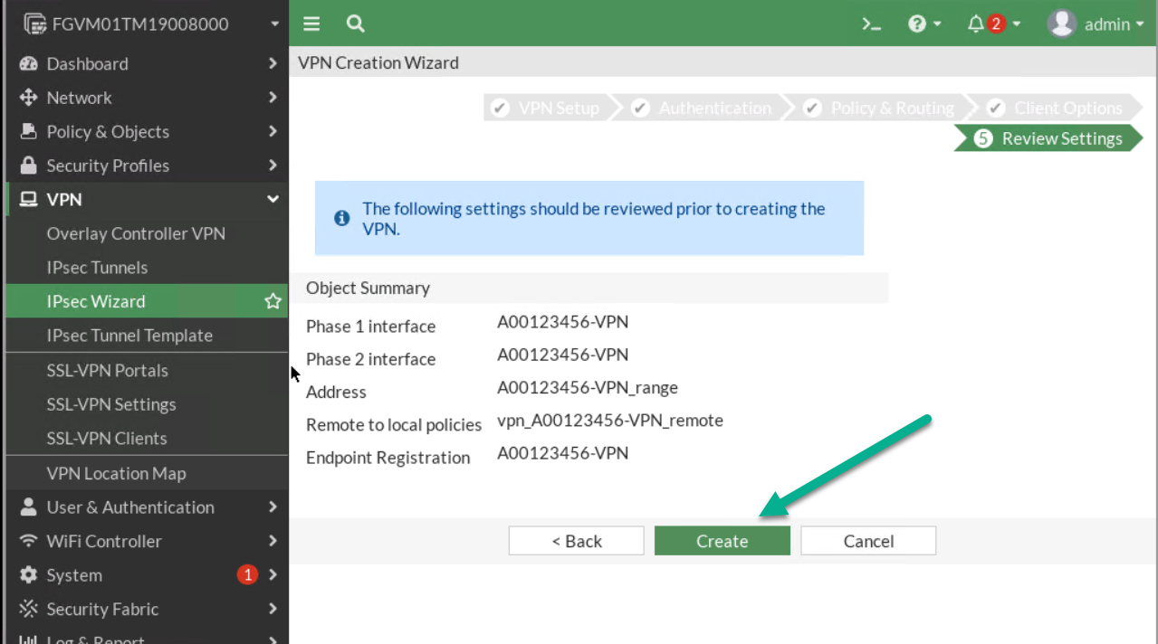
Figure 4.18: Review Settings
- First:
- On Windows machine, download FortiClient from Fortinet. Install the FortiClient and configure IPsec as set in the previous steps. Your remote Gateway IP should be the Port1 IP address.
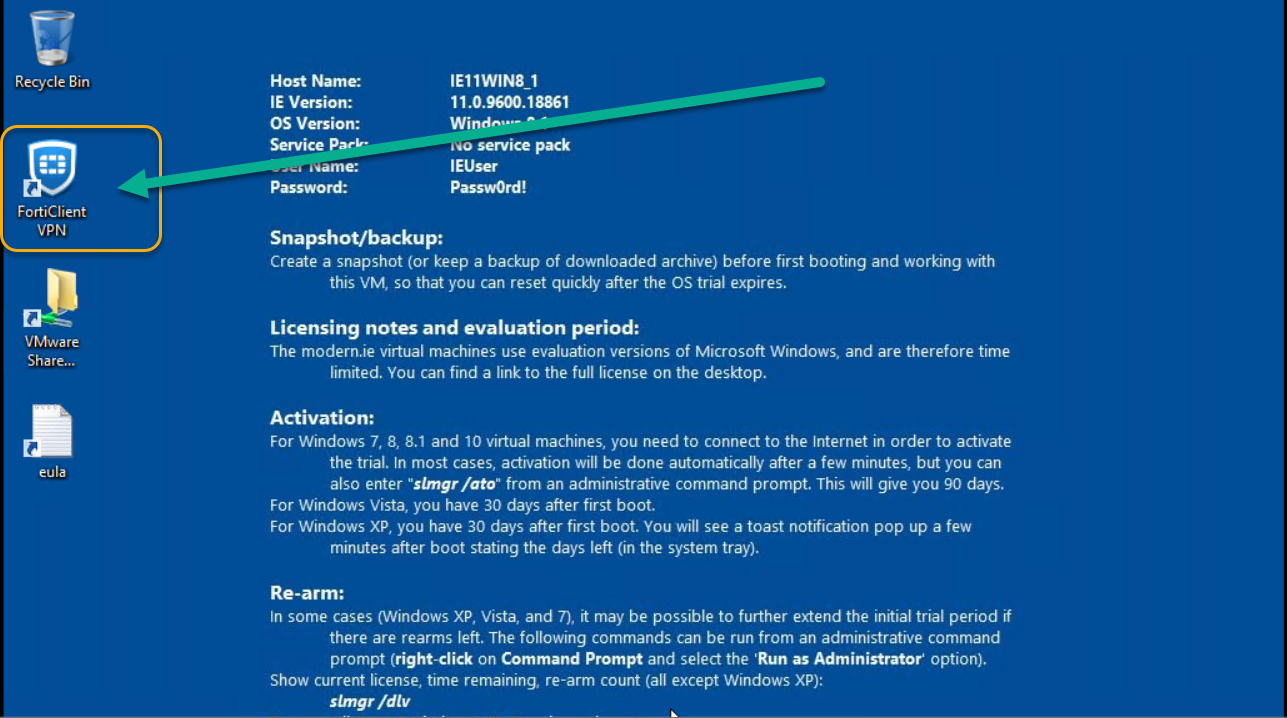
Figure 4.19: Install FortiClient on Windows -
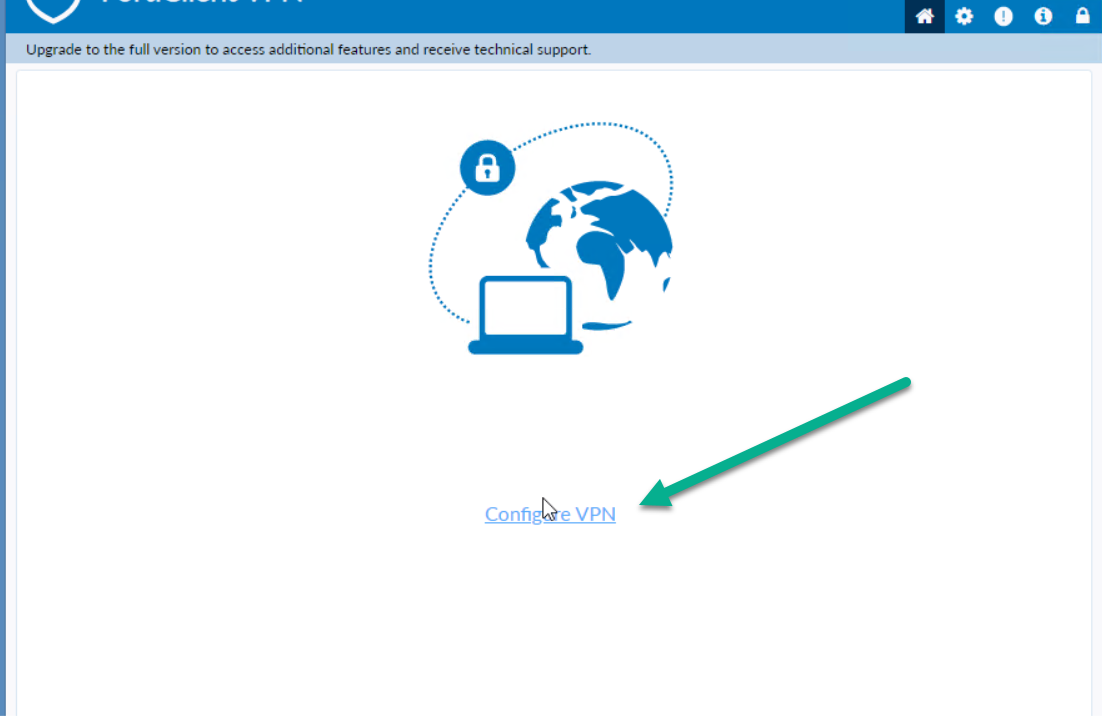
Figure 4.20: Configure VPN in FortiClient -
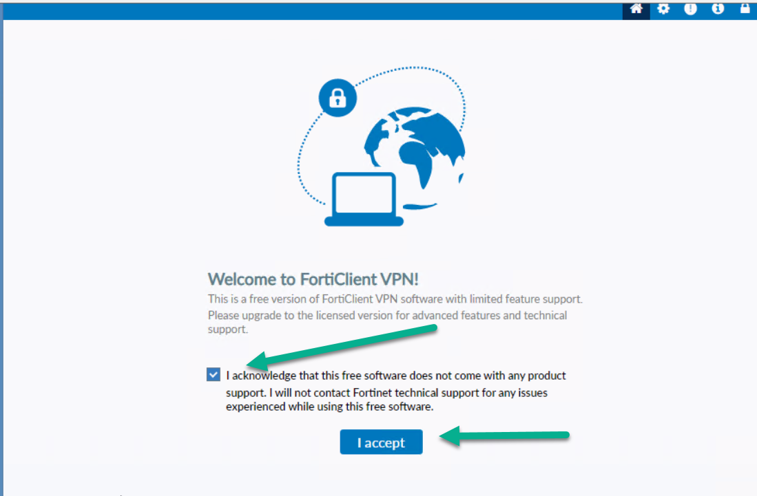
Figure 4.21: Accept FortiClient Free Licence -
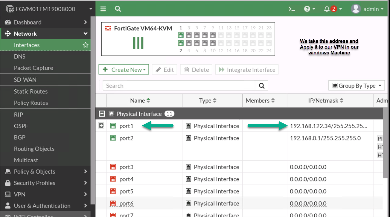
Figure 4.22: Port1 IP Address -
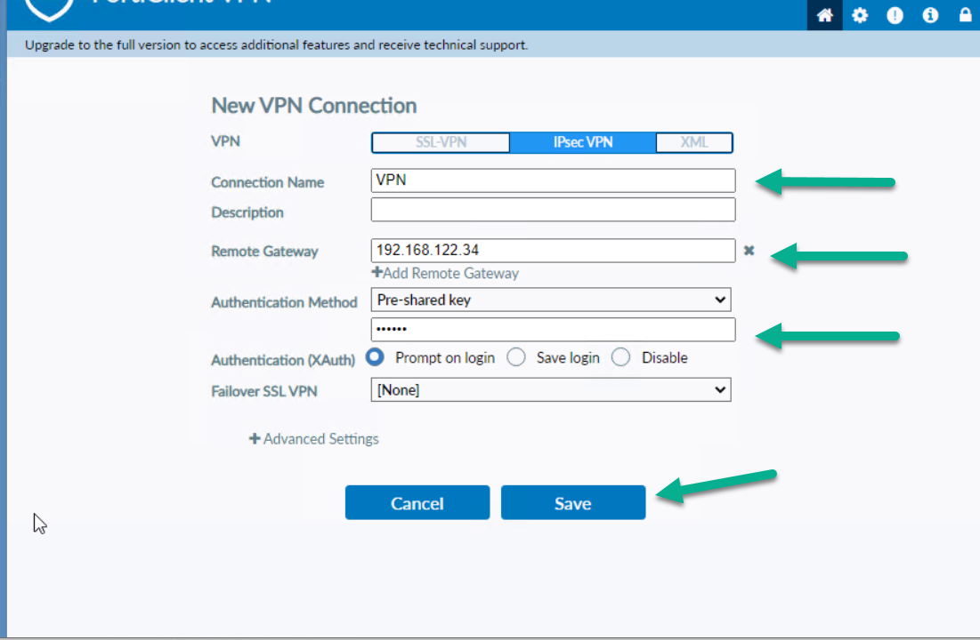
Figure 4.23: Configure FortiClient Remote Gateway and Pre-shared key - You should be able to ping from Windows to VPC.
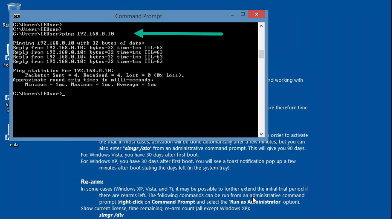
Figure 4.24: Verify configuration
Site-to-Site VPN (IPsec VPN)
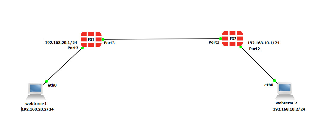
Scenario: We are going to have IPsec VPN from WebTerm1 to WebTerm2. First, we are going to configure both firewalls through IPsec VPN Wizards and then we will verify connectivity from WebTerm1 to WebTerm2.
To validate Firewalls licences, we are going to connect them to the Internet.
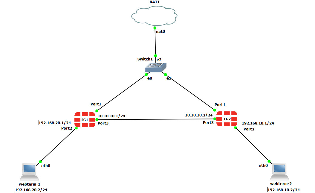
| Device | IP address | Access |
|---|---|---|
| Fortigate1 | 10.10.10.1/24 | ICMP-HTTP-HTTPS |
| Fortigate2 | 10.10.10.2/24 | ICMP-HTTP-HTTPS |
| WebTerm1 | 192.168.20.2/24 | – |
| WebTerm2 | 192.168.10.2/24 | – |
Note:Port1 is used for firewall licensing. Once the license is successfully applied, you can disconnect port1.
- On the FG1, go to VPN > IPsec Wizard and select Site to Site – FortiGate.
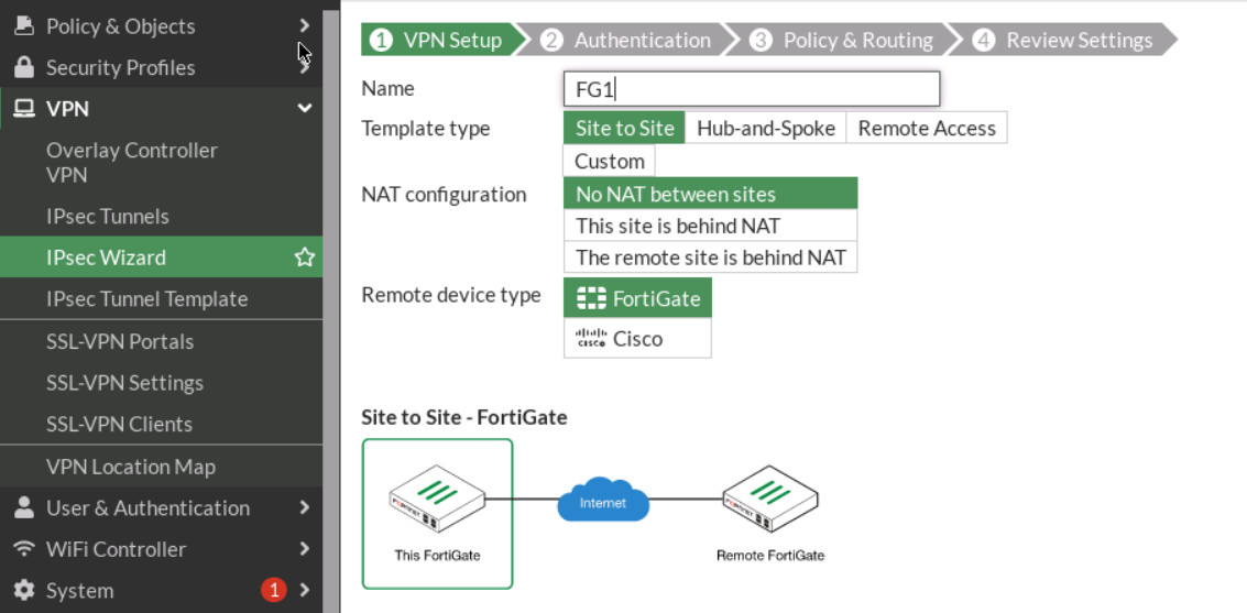
Figure 4.27: VPN Setup - Select Site2Site/ FortiGate /No Nat. Enter Remote IP: 10.10.10.2/24, outgoing interface: port3.
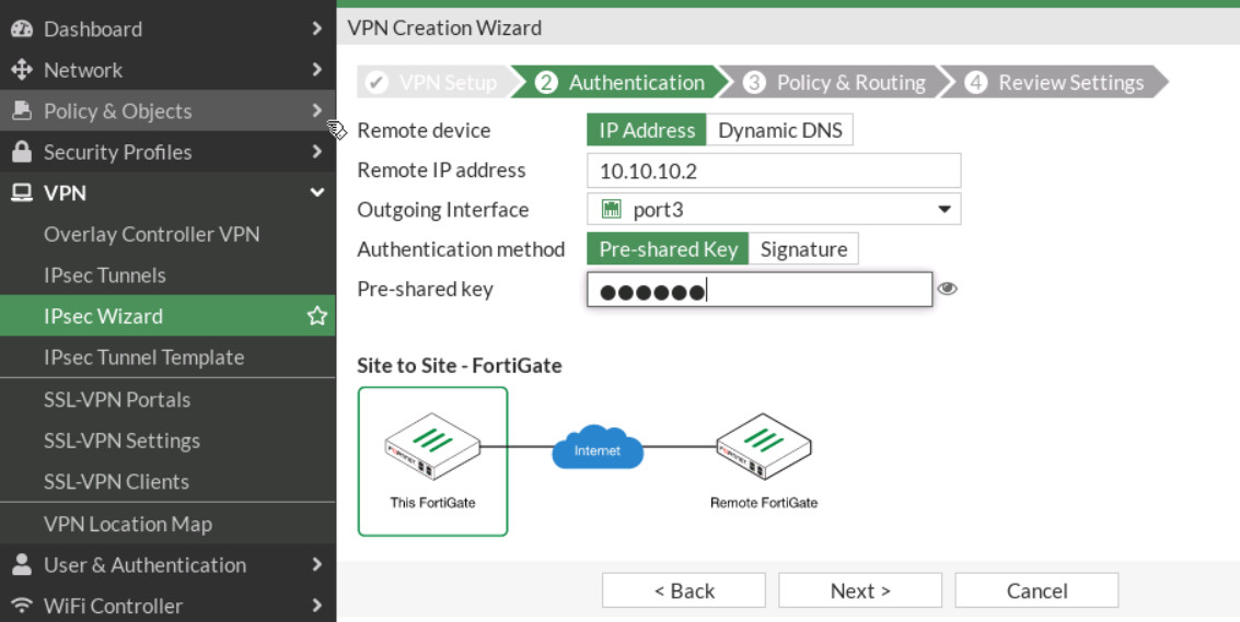
Figure 4.28: Authentication - Local Interface: port2, IP: 192.168.20.0/24, Remote subnet: 192.168.10.0/24. Through the wizard, FortiGate creates two policies and two static routes in the firewall.
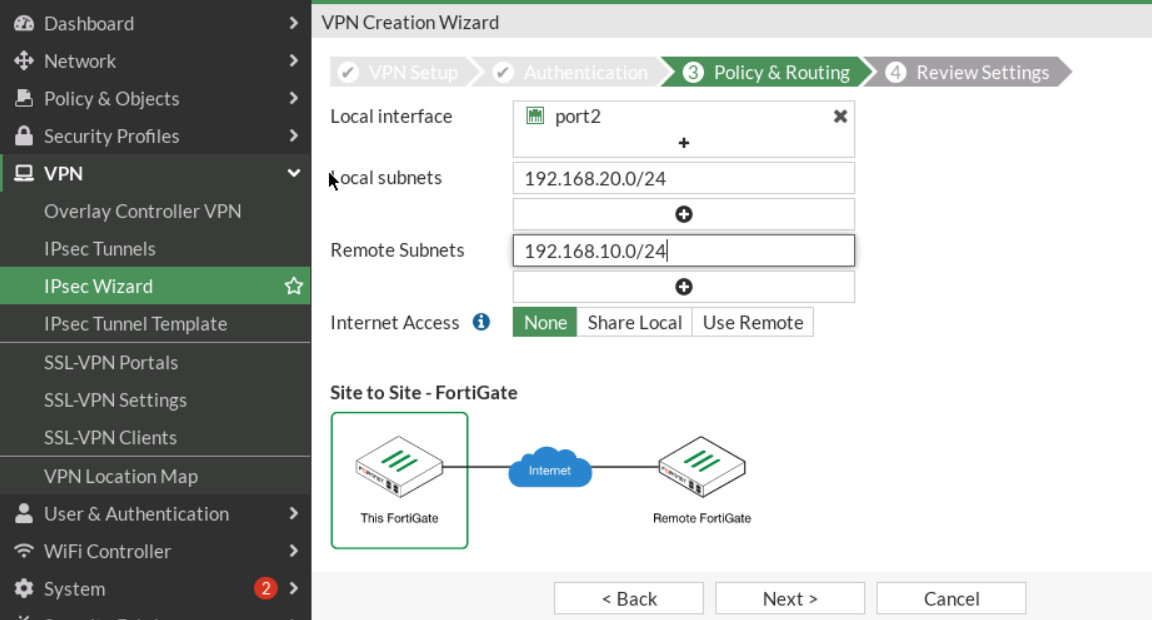
Figure 4.29: Policy & Routing - On the FG2, go to VPN > IPsec Wizard and select Site-to-Site – FortiGate.
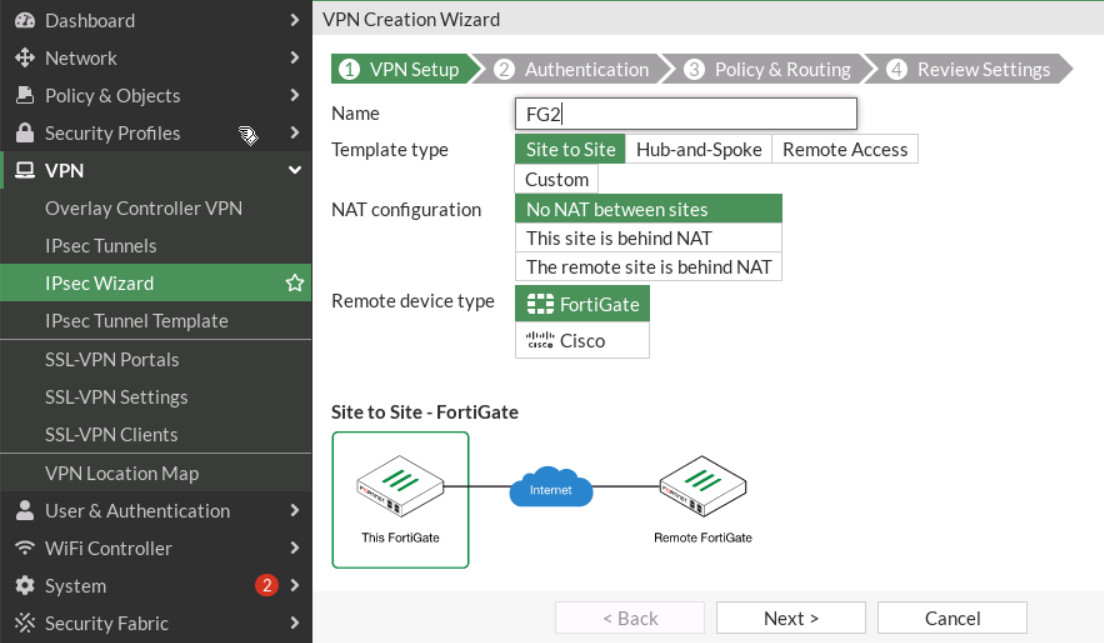
Figure 4.30: Set up FG2 - Do the same configuration for FG2 (remote IP is 10.10.10.1/24 and local IP is 192.168.10.0/24).
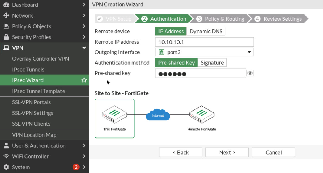
Figure 4.31: Authentication in FG2 -
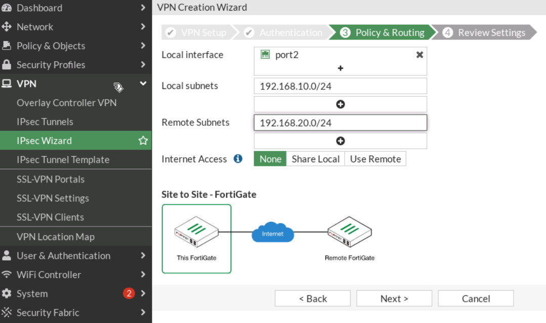
Figure 4.32: Policy & Routing in FG2 -
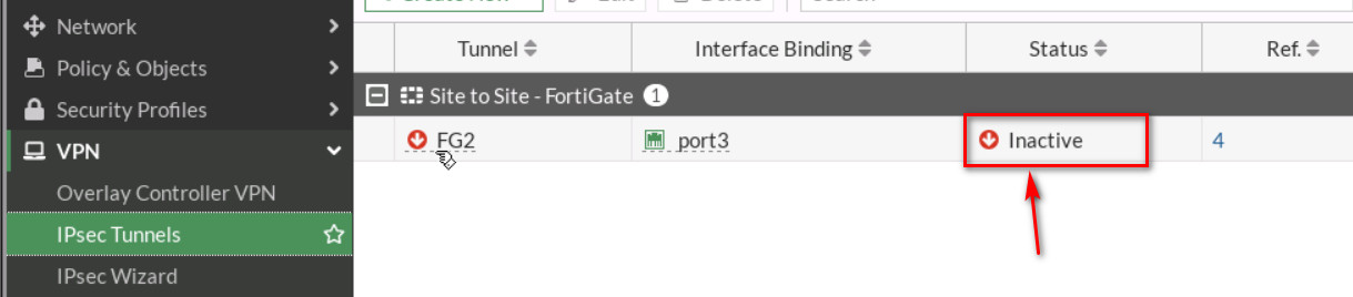
Figure 4.33: Configure IPsec Tunnels Then, go to your IPsec Tunnels and double click on Inactive.
On the next windows, right click on the tunnel > Bring UP > All Phase 2 selectors. Then, your tunnel should be up!
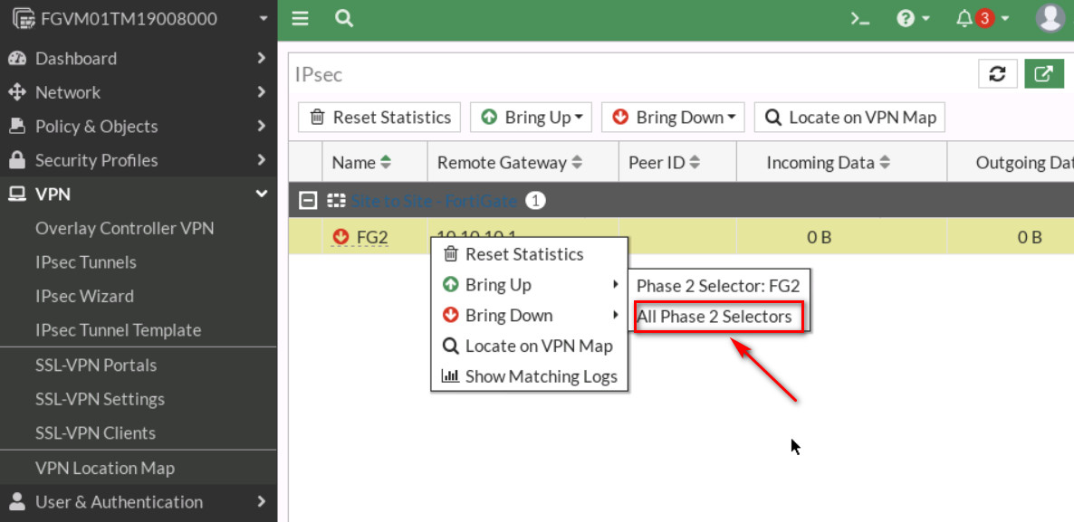
Figure 4.34: Bring up IPsec Tunnel 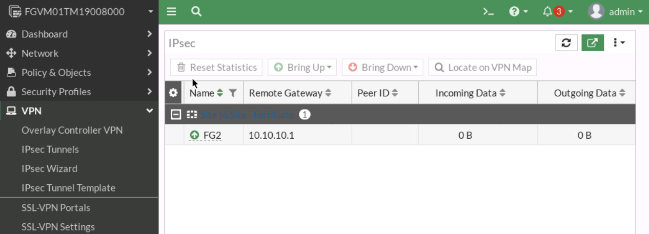
Figure 4.35: Verify the status of the tunnel - Go to Logs & Reports > Event > VPN Event and verify your configuration.
-
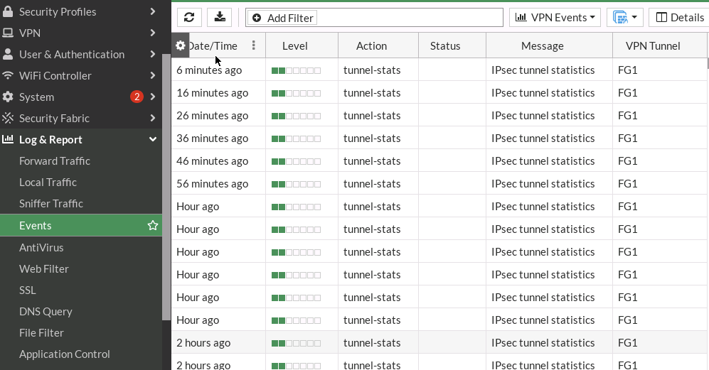
Figure 4.36: Verify the logs - You should be able to ping from WebTerm1 to WebTerm2.
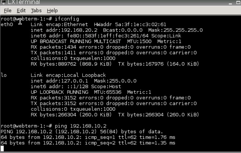
Figure 4.37: Verify configuration
