8 Square to Round on a Pitch
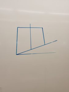
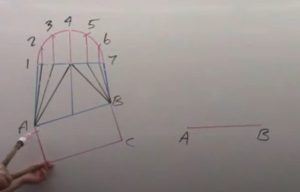
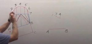
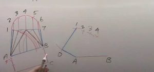
- Draw a complete elevation view. Keep in mind that any plan view would need to be projected from the elevation view to keep the end on a pitch to correct shape, it will not be viewed as the original size in a plan view because of the pitch.
- Draw profiles at each end of the elevation view. The square end will be a rectangular profile, while the round will be a half round shape.
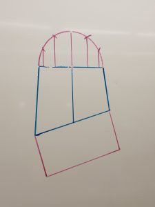
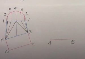
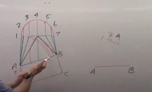
- Draw in all element lines and label the elevation view. It is recommended to use letters on the square end and numbers on the round.

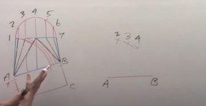
- Start the pattern by drawing the True Length (TL) of line A-B on a horizontal plane, remember that this line is a true length in the elevation view. Similar to plan view triangulation, a square to round should always be started from a horizontal line, A-B.
- Find the TL of line A-4. Swing the element line A-4 from point A and transfer it to the baseline A-B of the elevation view. Note: The baseline A-B may need to be extended to fit A-4.
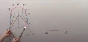
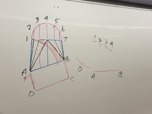
- Next we will find the “difference in profile” for this line. Take profile line at point 4 and transfer it to line D-A of the profile on the elevation view. It must be started from the outside of the profile, point D, and work inwards. This leaves the difference at the 90 deg corner of D-A-B.

- The TL of line A-4 will be the hypotenuse of the triangle we just made. From the difference in profile to the length of line A-4 on the baseline.
- Pick up the TL of line A-4 and swing it from point A on the pattern.
- Find the TL of line B-4. Pick up element line B-4 from the elevation view and swing it to the baseline.
- Take profile line 4 and transfer it to line C-B, starting from the outside again.
- Pick up the TL of line B-4 and swing it from point B on the pattern. This has now created point 4 on our pattern.
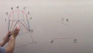
- Now, we will keep working one side of the fitting. Pick up element line A-3 and swing it to the baseline.
- Take profile line 3 and transfer it, starting from point D, along line D-A.
- Pick up the TL of line A-3 and swing it from point A on the pattern.
- Take step off 4-3 from the profile and swing it from point 4 on the pattern. This has created point 3.

- Pick up line A-2 from the elevation view and swing it to the baseline.
- Take profile line 2 and transfer it from point D along line D-A.
- Pick up the TL of line A-2 and swing it from point A on the pattern.
- Take step off 3-2 from the profile and swing it from point 3 on the pattern. This has created point 2.
- Pick up line A-1 from the elevation view and swing it to the baseline.
- Since there is no line at profile 1, we use all of line D-A as the difference. We still need to think of this as a difference, so line A-D minus 0 is the full length of line A-D. The full length is the difference, so the TL is taken from point D.
- Pick up the TL of line A-1 and swing it from point A on the pattern.
- Take step off 2-1 from the profile and swing it from point 4 on the pattern. This has created point 1.
- The next point creates the wings of the fitting. When we look at the elevation view, we have 2 lines which overlay each other. Both A-1 and D-1 look to be the same, but they are not. Line A-1 comes from the front of the fitting to the center, that’s why we need to find the true length. Line D-1 goes from center to center, meaning it is standing straight up, without leaning over. Line D-1 is the only one which is a true length in the elevation view. We can take line A-1 directly as the true length of line D-1 because there is no profile left at either end. The outside edges are always true lengths because they are on center and we know they are not leaning.
- Swing the TL of line D-1 from point 1 on the pattern. Notice that every line we swung upwards, we needed to find the true length, but the 1 line we swung downward was a true length directly in the elevation view. This is always the case and should be remembered as an important part of this process.
- Pick up line A-D from the profile of the elevation view, (this is a true length) and swing it from point A on the pattern. This creates the wings which need to be 90 deg at point D. Again, both lines that form the wings are true lengths directly from the elevation view!!!
- Repeat the entire process for the other side until the full half pattern is complete.
