Learning Task 1
Describe Sewers
A plumber’s responsibility for a drainage system on private property ends at the property line. The municipal or city system starts at the property line and ends at the eventual location where the treated effluent is returned to the earth. Although the materials and methods discussed in this learning task are overseen by engineers where they exist on public property, they are inherently like those encountered on private land. It is important to reinforce the fact that any work undertaken on drainage systems that exist beyond private property lines are not part of a plumber’s sphere of work; they are performed by municipal or city personnel and as such are not governed by the National Plumbing Code of Canada (NPC).
There are essentially three different types of sewer systems and they each have a unique purpose. They are:
- sanitary sewers
- storm sewers, and
- combined sewers.
All three of these sewer systems can be found in private and public systems. They play important roles in ensuring that the waste we produce is transported and treated properly. Although a sewer that exists on private property is correctly named a building sewer, for the purposes of explanation we will simply refer to them and those on public property collectively as sewers.
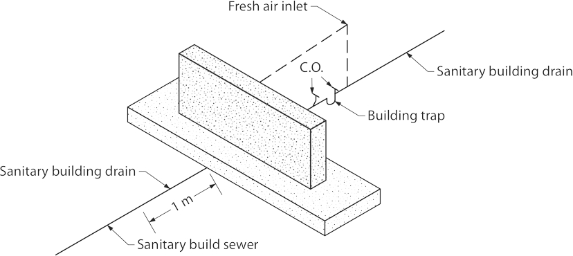
Sanitary Sewer System
The main purpose of a sanitary sewer is to carry liquid and solid waste away from homes and businesses and direct them to places of final treatment such as wastewater treatment plants. These systems are specifically designed to handle human solid waste and easily degradable manufactured solids such as toilet paper and tissues. They may consist of many kilometres of piping which are connected to manholes and pumping stations. The pumping stations, often known as lift stations, help to propel the waste through the system to the wastewater treatment plant. From the treatment plant, the treated effluent is returned safely to the environment.
Storm Sewer System
Storm sewer drainage systems are crucial in the prevention of flooding. They help to divert excess rain and groundwater which runs off impervious surfaces such as parking lots, roofs, paved streets, and sidewalks into nearby waterways through a system of drains and underground pipes. Unlike the sanitary sewers that carry waste to a treatment plant, the storm sewer system carries untreated runoff water directly into the environment.

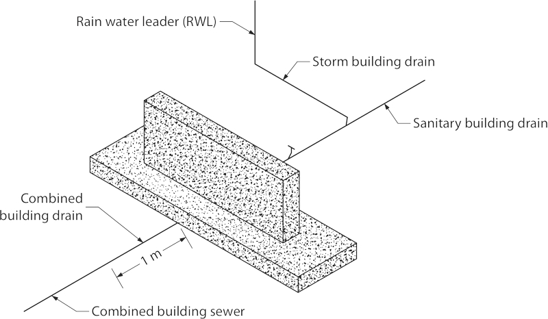
Combined Sewer Systems
These types of sewer systems are exactly what they sound like, which is a combination of sanitary sewer systems and storm sewer systems. Sewage and storm water are channeled through the same pipe, eventually terminating in a sewage treatment plant, which can pose problems. In times of extreme rainfall or flooding, these systems can overload the capacity of the treatment plant. They can back up and overflow causing untreated wastewater to flow directly into the environment. This allows for dangerous pathogens and pollutants to make their way into surface and groundwater, posing a serious threat to people’s health. Therefore, their use is very particular in that they are typically found in areas where it is very difficult or impossible to direct storm water to a safe disposal location such as a river or lake. Stormwater and sewage should never be introduced into common piping unless specifically mandated by the local Authority Having Jurisdiction.
Sewer Piping Material
The selection of piping material for use on private property is governed by the plumbing code in force in the area. Remember that the choice of pipe used in systems beyond the property line rests solely on the shoulders of the municipal engineers and staff.
In the NPC, subsections 2.2.5, 2.2.6. and 2.2.7 specify uses and conditions for pipes meant to be used in building sewers. For ease of use, Table A-2.2.5., 2.2.6. and 2.2.7 in the “Notes to Part 2 Plumbing Systems” lists, in tabular form, the pipe types acceptable for this use. The general material types listed there are:
- asbestos cement
- concrete
- vitrified clay
- polyethylene
- plastic
- ABS
- PVC
- polyolefin
- cast iron
- ductile iron
- stainless steel
- corrugated galvanized
- copper, and
- brass
Although this list is quite extensive, many of the materials are specific in their purpose and so are not commonly used for sewers that progress beyond the property line to become part of a city or municipal system. Therefore, we will restrict our study to only the most common pipe types that may be newly installed as building sewers or under public streets as part of a new storm, sanitary or combined drainage system.
ABS Pipe
Acrylonitrile-butadiene styrene (ABS) pipe has been the most common replacement option for old cast iron and copper drainage pipe in residential use since the early 1970’s. It is the most predominant type of pipe used for residential drainage systems in British Columbia. Although weaker and less resistant to acids than PVC pipe, it is easier to handle, cut and connect. The cellular core variety of ABS is most common due to its light weight and cost.

Readily available diameters for building sewer purposes range from 75 to 150 mm (3 to 6”) with larger sizes available by special order. The most common pipe length is 3.67m (12 ft) although lengths of 3m (10 ft) and 6m (20 ft) are also available. Because of its fairly small available diameters when compared to those of PVC and concrete piping, it is rarely seen as a component of a municipal system.
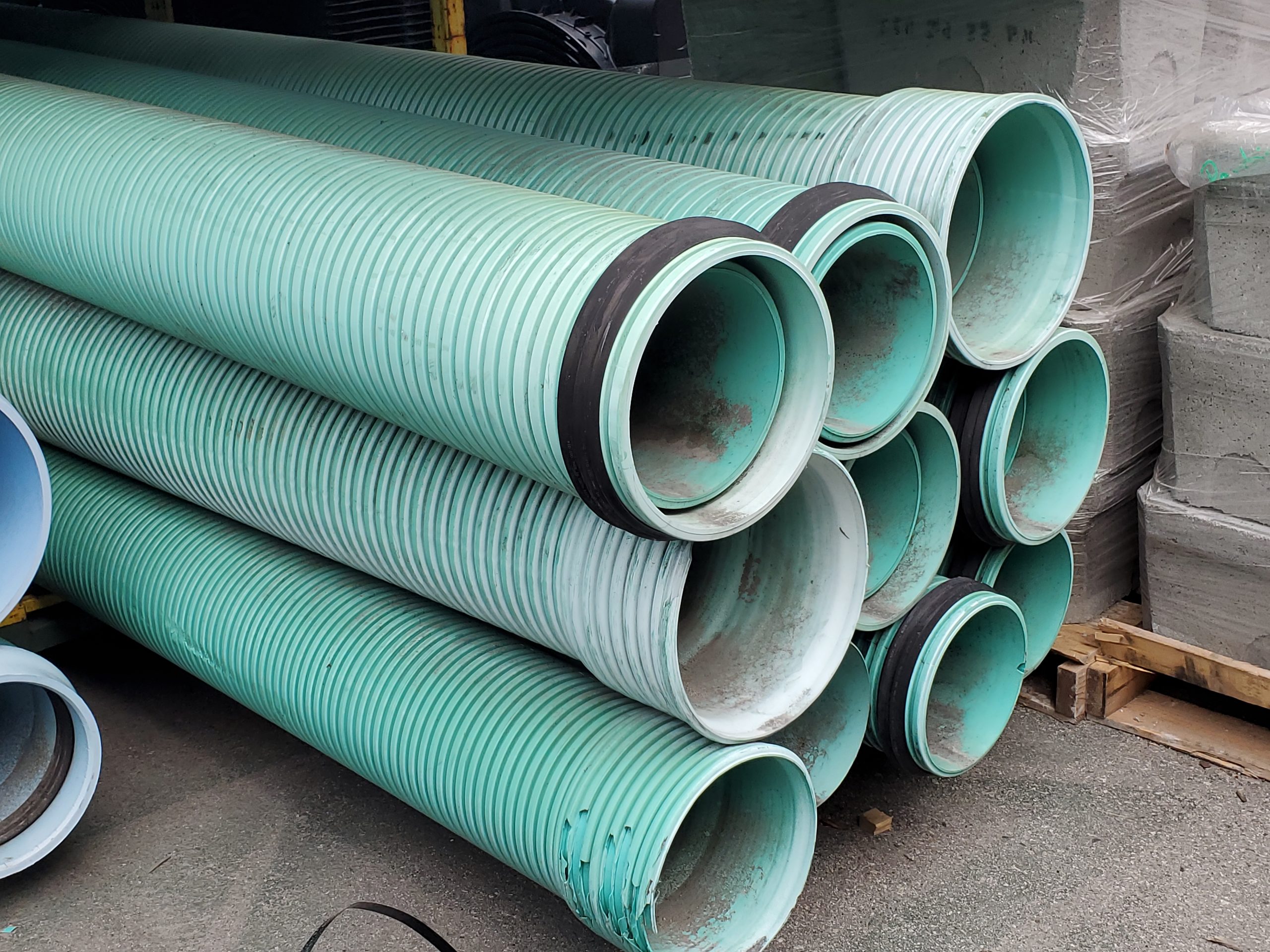
PVC Pipe
PVC (polyvinyl chloride) is one of the oldest synthetic piping materials. PVC is a thermoplastic, meaning it can be softened and reformed, and a fusible version is now available, which competes with HDPE in trenchless construction. This pipe is very corrosion resistant and is often used to coat other materials that are affected by acidic conditions. Cost and longevity are large reasons why municipalities are drawn to PVC. Even when including backfill and labor expenses, PVC is typically a less expensive replacement option than other materials. An AWWA (American Water Works Association) Research Foundation study estimates the life expectancy of PVC to be more than 110 years. Pipe sizes range from 100 mm to 1.5m (4 to 60 inches) for sewer applications with common lengths of 6m (20 feet). Its light weight, longevity, and options of joining methods (mechanical, gasketed or glued) make PVC a popular choice of municipal engineers.

HDPE pipe
HDPE (high-density polyethylene) pipe has also become a popular choice for wastewater applications because of its noncorrosive, highly flexible characteristics. Joints are either heat-fused (common for pressure systems) or bell-and-spigot and mechanical (for drainage use). Pipe interiors and exteriors can be either corrugated (ribbed) or smooth depending on the pipe’s intended function. Like PVC, HDPE is highly resistant to corrosion and has a low failure rate, which further decreases life span costs. The pipe is offered in diameters from 100 mm to 1.5m (4″ through 60″), in nominal 6m (20 ft) lengths.
Concrete pipe
RCP (reinforced concrete) pipe is mainly used in municipal gravity systems. Its high strength offers protection from crushing loads primarily when used at shallow depths. Precast gravity-flow pipe is manufactured in several shapes, including round, elliptical, arched and box, and is used in sanitary sewers, storm drains and culverts. Despite its durability, concrete is susceptible to H2S (hydrogen sulphide) attacks, and in extremely acidic soil, it can corrode. To combat these problems, concrete pipe can be coated with a plastic lining, and special measures can be used to prevent exterior corrosion in acidic soils. Depending on manufacturer, sizes can range from 300 mm (10 inches) to 3m (10 feet) in diameter, with lengths of 1.25m (4 feet) to 2.45m (8 feet).
Its weight dictates the pipe’s short lengths which increases the number of joints needed and necessitates the use of large equipment for handling and placing.
Hazards Associated with Sewer Work
Workers face conditions that may be immediately dangerous to life or health when entering sewer systems for repair or maintenance. Knowledge of the dangers involved, training in safe work procedures, and the correct use of safety equipment are essential to ensure that workers are protected from injury.
Responsibilities
Where the employer is operating under contract (contractor), the owner of the sewer system (or prime contractor if one is appointed) is required to ensure that the employer carries out their responsibilities under the local OHS legislation. The employer is responsible to develop safe work practices, ensure that workers are provided with adequate training on the practices and ensure that these practices are followed. The employer must assess hazards at the work site and ensure appropriate controls are in place to protect workers. The following are the most common workplace hazards involved with work on sewers.
Trenches
Cave-ins pose the greatest risk to workers and are much more likely than other sewer-related accidents to result in worker fatalities. Other potential hazards include material handling, falls, unstable loads, and incidents of contact involving mobile equipment.
An unprotected trench can be considered an early grave, in that one cubic meter of soil can weigh as much as a car. Unprotected trenches cause dozens of fatalities and hundreds of injuries each year. Trench failures occur more often in winter and early spring when ground moisture content is higher, as additional pressure from water in the soil contributes to trench failure. No one should ever enter an unprotected trench. Trenches and excavations over a certain depth (e.g., 1.2m (4 ft) in British Columbia) require a protective system such as sloping or shoring unless the excavation is made entirely in stable rock.
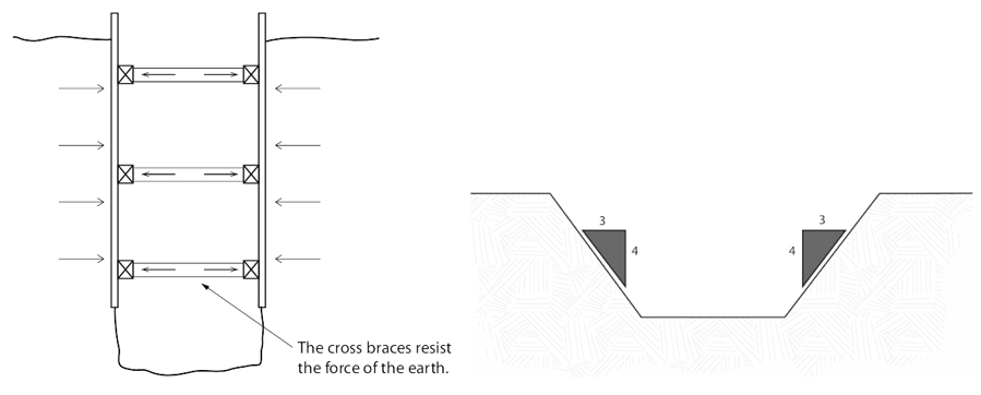
Hazards still exist at shallow depths, and a competent person is needed to determine if a protective system is warranted. Examples of trenching and shoring methods are covered in the Level 1 Plumber Apprenticeship Learning Guides.
Confined Spaces
WorkSafeBC’s OSH Regulation: Part 9 includes this definition of a confined space:
“confined space”, except as otherwise determined by the Board, means an area, other than an underground working, that
- is enclosed or partially enclosed,
- is not designed or intended for continuous human occupancy,
- has limited or restricted means for entry or exit that may complicate the provision of first aid, evacuation, rescue or other emergency response service, and
- is large enough and so configured that a worker could enter to perform assigned work.
A space may also be a permit-required confined space if it has a hazardous atmosphere, the potential for engulfment or suffocation, a layout that might trap a worker through converging walls or a sloped floor, or any other serious safety or health hazard.
The current Confined Spaces standard is a component of provincial Worker Compensation Board (WCB) legislation. The following are examples of some of those requirements for safe entry of confined spaces.
- Preparation: Before workers can enter a confined space, employers must provide pre-entry planning. This includes:
- Having a competent person evaluate the work site for the presence of confined spaces, including permit-required confined spaces.
- Once the space is classified as a permit-required confined space, identifying the means of entry and exit, proper ventilation methods, and elimination or control of all potential hazards in the space.
- Ensuring that the air in a confined space is tested before workers enter, and at specified intervals thereafter, for oxygen levels, flammable and toxic substances, and stratified atmospheres.
- If a permit is required for the space, removing or controlling hazards in the space and determining rescue procedures and necessary equipment.
- If the air in a space is not safe for workers, ventilating or using whatever controls or protections are necessary so that employees can safely work in the space.
- The employer must implement additional specific requirements in the OHS legislation regarding hazard assessment.
- Workers are responsible for carrying out their work in a manner that does not endanger them or their fellow workers. Workers must cooperate with their employer by following safe work procedures and using the equipment provided to complete the job safely.
Confined Spaces Air Quality Hazards
Air quality hazards are the most immediate of the concerns regarding confined space entry. Those concerns can originate from:
- insufficient amount of oxygen for the worker to breathe.
- toxic gases that could make the worker ill or cause the worker to lose consciousness.
- The presence of asphyxiants. Simple asphyxiants are gases which can displace oxygen in the air. Low oxygen levels (19.5 percent or less) can cause symptoms such as rapid breathing, rapid heart rate, clumsiness, emotional upset, and fatigue. As less oxygen becomes available, nausea and vomiting, collapse, convulsions, coma and death can occur. Unconsciousness or death could result within minutes following exposure to a simple asphyxiant. Asphyxiants include argon, nitrogen, or carbon monoxide. It is important to note that wherever there is ferrous piping present, the rusting process can use up the available oxygen in a confined space, contributing to the likelihood of asphyxiation.

Other hazards of confined spaces include:
- Chemical exposures due to skin contact or ingestion (as well as inhalation of toxic gases).
- Fire hazard – An explosive or flammable atmosphere due to flammable liquids and gases and combustible dusts which, if ignited, would lead to fire or explosion.
- Process-related hazards – such as residual chemicals, or release of contents of a supply line.
- Biological hazards – viruses, bacteria from fecal matter and sludge, fungi, or molds.
- In warmer climates, the presence of dangerous animals and insects
Pinch Points
A pinch point is produced when two objects come together and there is a possibility that a person could be caught or injured when entering that area. Pinch points commonly impact fingers and/or hands but can involve any area of the body. The injury resulting from a pinch point could be as minor as a blister or as severe as amputation or death. Conveyors, gears, loaders, compactors and other moving equipment are examples of machinery with pinch points.
Common causes of injuries from pinch points are:
- Not paying attention to the location of hands and feet
- Walking or working in areas with mobile equipment and fixed structures
- Loose clothing, hair or jewelry getting caught in rotating parts of equipment
- Poor condition of equipment and guarding
- Dropping or carelessly handling materials or suspended loads
- Not using the proper work procedures or tools
- Reaching into moving equipment and machinery
Hoists
When lifting and hoisting sewer piping materials on site, incidents may occur for a variety of reasons. The main causes include but are not limited to the following:
- Unintentional contact with a moving load will often result in serious or fatal consequences due the masses involved. Examples include workers that are responsible for landing and stacking loads getting caught between a solid surface and the moving load, or loads being moved before all workers have moved clear of the lifting zone, and workers getting crushed by the load. This latter situation can also be exacerbated if the load’s centre of gravity is unsafe, causing it to start swinging unexpectedly and uncontrollably.
- Lifting equipment can overturn for a variety of reasons. A common cause involves not using or fully extending the outriggers to provide a solid platform or setting up a crane on non-compacted/disturbed ground. The ground underneath may appear to be solid, but it can be deceptive. As a load is moved and weight transfers over the outriggers, they can start to sink into the soil.
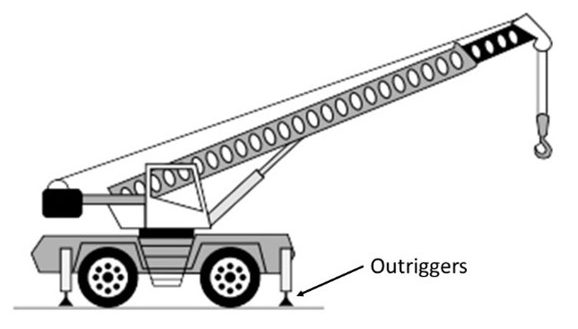
Figure 10 Mobile Crane - Proximity to overhead power lines is one major factor that is either overlooked or not understood. The crane boom/forklift truck does not actually have to come into direct contact with the power line for a dangerous condition to occur. The electric current in the lines can “arc” through the air when a grounded point is within a certain distance. This distance is determined largely by the voltage – the higher the voltage the greater the arc distance. Therefore the available voltage in the lines will determine the safe “limits of approach” as shown below.
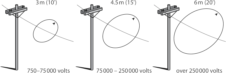
Figure 11 Limits of approach - In many cases the operator sitting in the cab may be isolated from the current and will not typically feel anything, but they are at significant risk if they attempt to leave the lifting equipment while the current is still flowing, as once they grab the structure and place a foot on the ground the current may then pass through their body to earth.
- Mechanical failure doesn’t occur as frequently as do some of the events described previously but is still relevant. Installed safety devices such as a safe working load indicator can fail. Braking systems, hydraulic systems and electrical systems are all vulnerable to failure. The very nature of the way that lifting devices are typically used, moving between locations, working in a wide variety of environmental conditions all add significantly to the wear and tear on this equipment. The key factor here for prevention is the systematic inspection, testing and certification of lifting and hoisting equipment. Whilst a slightly different mechanism of failure, it is also worth considering the condition and integrity of lifting accessories such as slings, shackles and hooks. These devices can also fail with catastrophic results.
- Dropped objects is a hazard that can occur in several ways. Objects may fall off the crane, the load or parts of it could fall or objects hidden within it may fall. If not secured properly, it is quite common for items to shift once the load is raised and then fall to the ground. For example, where items are left on a load by mistake (e.g., hand tools) or are hidden from view (e.g., rocks or other solid materials in pallet pockets), once the load is airborne these objects may be dislodged and fall.
- Climbing onto a load as it is being lifting or set in place such as when riggers/slingers have to climb on top of loads to either attach a sling to a hook or vice versa. Climbing on top of the load can be problematic as there is normally no safe access and no fall protection in place.
Sewer System Types, Applications and Operations
Sewer system design and application date back to ancient times, and many of the technologies used in past centuries are still seen in today’s sewer systems. The development of better sewer systems that can meet a variety of community and municipal needs has been ongoing. Demand for advanced scientific innovations and techniques in sewer systems continues to increase as the urban population increases, new contaminants emerge, and effluent standard requirements become more stringent. Some of these alternatives for sewer system designs are in full operation, while others are still evolving. New innovative sewer systems, commonly referred to as alternative wastewater collection system designs, include pressure sewer systems, vacuum sewer systems, and small diameter gravity sewer systems.
Gravity Sewer Systems
Gravity sewer systems, small and large, are by far the most used of any sewer system worldwide. In a gravity sewer system, pipes are installed on a slope that allows sewage and wastewater to flow by gravity from the household to lift stations and finally to the wastewater treatment plant. They are sized with as straight an alignment as possible and a uniform gradient to maintain self-cleansing velocities. Gravity sewers are typically installed at a depth of one meter (3 ft) or more and to a maximum of approximately 7.6 meters (25 ft).
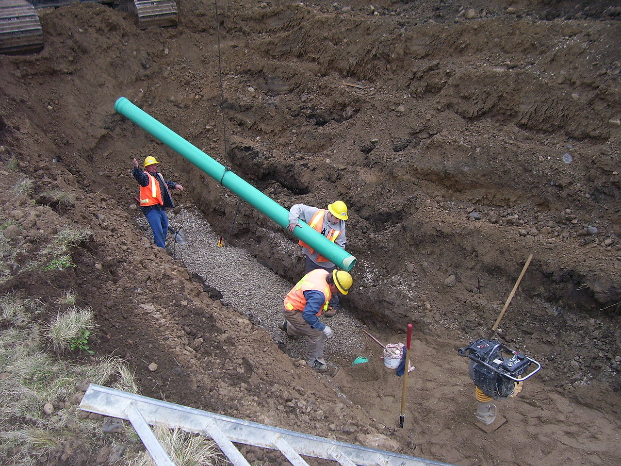
Materials used for a gravity sewer conveyance system include but are not limited to reinforced concrete pipes (RCP), specialty plastic pipes, polyvinyl chloride pipes (PVC), and Centrifugally Cast Fiberglass Reinforced Polymer Mortar (CCFRPM) pipes.
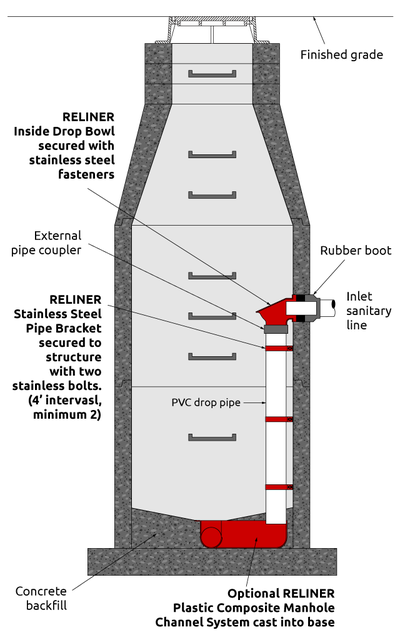
Manholes are installed at various locations along sewer systems. Spacing of municipal sewer manholes ranges from 400-900 ft. (122 – 275m). Manhole spacing on private property is mandated by clauses in the NPC. Manholes are required under the following conditions:
- at both ends of horizontal curves
- at the intermediate point of a curve with angle greater than 90°
- at the point of reverse curve
- at abrupt change in vertical alignment
- at changes in pipe size, and
- at the confluence of three or more pipes.
More information regarding manholes will be covered further in a later section of this learning guide.
Pressure Sewer Systems
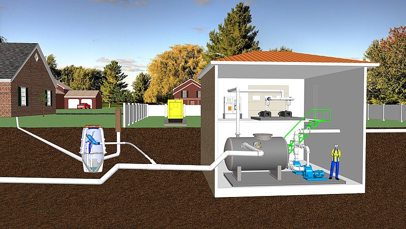
A pressure sewer system is commonly used when a gravity system is impractical, such as in rocky areas, areas with high groundwater table, around lake areas where homes are built fronting the lake, and in flat terrains over long distances. It is also commonly used within buildings where the building sewer elevation is higher than that of the gravity drainage piping feeding into it. It is comprised of a small diameter pipeline under pressure head generated by a grinder pump. The pump is located in a tank either inside the building basement or buried outside the building. The pump pushes a sewage slurry into a municipal or district system which may itself operate by gravity or be pressurized. Typical main pipe diameters range between 50 to 150 mm (2 in to 6 in). Solvent welded polyvinyl chloride (PVC) is the most-used piping material. For more detailed information, including a video, visit E/One Sewer Systems in Canada.
Vacuum Sewer System
The vacuum sewer system consists of three major components: a service holding tank/valve pit, a collection piping/vacuum main and a vacuum station. In vacuum sewer systems, wastewater flows by gravity away from the building through a small diameter pipe to a sump and valve pit. A vacuum valve located inside the valve pit provides the interface between the collection main (vacuum main) and the sump, which is under atmospheric pressure. When a certain amount of sewage accumulates in the sump, the interface valve opens automatically, and the sewage is immediately sucked into the collection main which is under a light negative pressure of between 16 – 20 in of Hg created at the vacuum station. This negative pressure provides the energy that moves the sewage at a velocity of 15-18 fps. The collection system pipes, which are typically solvent welded PVC, HDPE, and O-ring rubber gasketed pipes, range in size between 3 and 10 inches. This system, like the pressure systems, can be used in areas with unstable soils, flat terrain, high water table, semi-urban/rural areas, rocky ground, and when the wastewater is of higher solids concentration. Like the pressure systems, these systems can be installed closer to ground level than gravity piping, requiring minimal slope.
Small Diameter Gravity Sewer
The small diameter gravity sewer is another advanced sewer system that provides primary treatment of the wastewater at each connection and releases pretreated wastewater to the collection main. This system consists of a house connection, interceptor tank, service laterals, collection mains, cleanouts, manholes, vents and lift stations. An interceptor tank or septic tank, with a detention time of 12-24 hours, collects the suspended solids from the house connection and then releases the pretreated wastewater to the service lateral which connects to the collection main. A well-designed interceptor or septic tank can remove up to 50% of biological oxygen demand (BOD5), 75% of suspended solids, 90% of grease, and all grit. This allows the municipal main to be laid at minimal slopes due to the relative absence of solids, while also allowing smaller main sizes. The typical diameter of service main pipes is three to four inches, with a slope of two percent. The collection main is also three to four inches in diameter, and it maintains a 1.5 fps velocity compared to a 2.5 fps velocity requirement for conventional gravity sewers. However, like a standard gravity system, there would have to be lift stations at intervals along the mains to prevent the mains from being buried too deep in the ground.
Hybrid Sewer System
The hybrid sewer system is a design that combines two or more of the above sewer system designs into one functional system. Examples of hybrid sewer systems are a combination of pressure sewer and gravity sewer, vacuum sewer and gravity sewer or a combination of vacuum sewer, pressure sewer and gravity sewer.
Now complete Self-Test 1 and check your answers.
Self-Test 1
Self-Test 1
- Where does a plumber’s responsibility for a drainage system on private property end?
- At the property line
- At the end of the building drain
- At the cleanout for the main drain
- At the connection of the sewer to the street main
- Which one of the following is not a type of sewer system?
- Storm
- Sanitary
- Drainage
- Combined
- Which one of the following is a system that contains both sewage from toilets and rainwater from roofs and parking lots?
- Storm
- Sanitary
- Drainage
- Combined
- Which one of the following choices is a type of pipe that was used in the earliest form of municipal waste systems and that may still be used where corrosive wastes may be expected?
- Vitrified clay
- Ductile iron
- Steel
- ABS
- Which one of the following choices is a type of pipe that is limited to use on private property, mainly due to its fairly small available diameters?
- PVC
- ABS
- HDPE
- Concrete
- Which one of the following is listed as being the most likely cause of worker fatalities associated with the installation of sewers?
- Pinch points
- Trench cave-ins
- Hoisting operations
- Confined space work
- Which one of the following choices is of the most immediate concern when entering a confined space?
- Air quality
- Fire hazard
- Biological hazards
- Chemical exposure
- A worker tries to walk around the back of an excavator and gets crushed between the counterweight and a pile of dirt. Which one of the following hazards would this be categorized as?
- Confined space hazard
- Confined space hazard
- Pinch point hazard
- Hoisting hazard
- What is the purpose of a lift station in a municipal sewer system?
- It is the location of the crane used for lifting
- It is a place where materials are readied for hoisting
- It pumps sewage from a deep sewer to a higher elevation
- It is the place where the sewage is disposed of into the environment
- Which one of the following choices is the most common type of sewer system in both private and municipal use?
- Hybrid
- Gravity
- Vacuum
- Pressure
Check your answers using the Self-Test Answer Keys in Appendix 1.
Media Attributions
- Figure 1 Sanitary building drain and sewer by ITA is licensed under a CC BY-NC-SA licence.
- Figure 2 Storm building drain and sewer by ITA is licensed under a CC BY-NC-SA licence.
- Figure 3 Combined building drain and sewer by ITA is licensed under a CC BY-NC-SA licence.
- Figure 4 Cellular core ABS pipe by Greg Wirachowsky is licensed under a CC BY-NC-SA licence.
- Figure 5 PVC sewer pipe by Greg Wirachowsky is licensed under a CC BY-NC-SA licence.
- Figure 6 HDPE sewer pipe by Greg Wirachowsky is licensed under a CC BY-NC-SA licence.
- Figure 7 Manhole components © Reliner, used with permission.
- Figure 8 Trench shoring and sloping examples by ITA is licensed under a CC BY-NC-SA licence.
- Figure 9 Examples of confined space air quality hazards by ITA is licensed under a CC BY-NC-SA licence.
- Figure 10 Mobile Crane was adapted from work by ITA is licensed under a CC BY-NC-SA licence.
- Figure 11 Limits of approach by ITA is licensed under a CC BY-NC-SA licence.
- Figure 12 PVC gravity sewer piping at substantial depth by Imprezzive1 has been released into the public domain.
- Figure 13 Vacuum sewer system by Srstevens3 is licensed under a CC BY-SA 4.0 licence.
