Learning Task 2
Size Pipe for Sewers
The following explanations are a synopsis of the sizing steps for sanitary, storm and combined sewers. These steps were originally covered in greater detail in Learning Modules D-1: “Install Sanitary Drain, Waste and Vent Systems” and D-3: “Install Storm Drainage Systems” of the BC Apprenticeship Learning Guides for Plumber.
Code Requirements for Sewerage Systems
Most provinces and territories in Canada have adopted the National Plumbing Code of Canada (NPC) as the accepted code for that jurisdiction. Provinces such as British Columbia and Ontario have chosen to create their own code by using the NPC as the base document and adding supplements to satisfy regional needs. For the purposes of explanations within this literature we will reference tables and clauses from the NPC; the same tables and clauses can be found in the BCPC, however the prefix “2” will be replaced by the prefix “7” where the BCPC is used.
Both codes have established a minimum acceptable standard for the design and installation of sanitary, storm and combined drainage systems on private property. The size of sewer is dependent on the hydraulic load on the pipe, the grade on the pipe and the Code table used for sizing. It is important to note that the NPC has no application on public property, although its clauses and tables can be used as guidelines. All aspects of sewer installations on public property are determined by engineers and their “good engineering practices”.
Sanitary Building Sewer Sizing
Sanitary sewers systems use fixture units (FU) to determine the hydraulic load imposed on the sewer system by the upstream fixtures or appurtenances. A fixture unit is not a flow rate unit but rather a design factor based on the rate of discharge, time of operation and frequency of use of a fixture. In original calculations arrived at by PDI (Plumbing and Drainage Institute) a fixture unit was equal to one cubic foot of water drained through a 1 ¼” OD pipe over one minute.
The fixture unit values of individual fixtures can be found in NPC tables 2.4.9.3 and 2.4.10.2.
The sizing procedure for a sanitary sewer is fairly simple:
- Determine the total number of fixture units from fixtures found in tables 2.4.9.3 and 2.4.10.2
- Add the flow from any semi-continuous or continuous flow appurtenances draining into it. These loads are normally expressed in L/sec, so they have to be converted into FU by applying the conversion number given in 2.4.10.3 (1) of the NPC, which is 31.7 fixture units per litre/second.
- Once a total flow rate of fixture units has been calculated, it is applied to Table 2.4.10.6.-C to establish the minimum size of sanitary building sewer required at the chosen grade.
Note: See the explanation and illustrations in A-2.4.10 of the NPC for an example of these sizing methods.
Additional loads to be added when sizing a storm drainage system include:
- If a clear-water waste appliance or fixture discharges a semi or continuous flow to the storm system, multiply its load in litres per second by 900 (the number of seconds in 15 minutes) to obtain the hydraulic load in L/15 min.
- If flow control roof drains are used, compute the discharge rate based on rainfall intensity, retention duration, accumulation height and roof area from the roof drain manufacturer’s data.
Add all the contributing hydraulic loads listed above to obtain the total hydraulic load on the storm building sewer in L/15 min. Using the appropriate pipe grade, consult table 2.4.10.9 of the NPC to select the sewer’s minimum size.
Shown below is a comparison example involving the introduction of a semi or continuous flow fixture into a sanitary system versus a storm system.
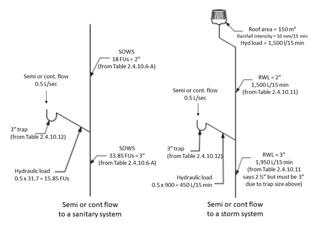
Note that, for the purposes of sizing the sanitary system downstream of the trap, the load must be expressed in fixture units. In the storm system, the load from the trap is expressed in L/15 minutes to be compatible with the tables used to size storm drainage.
Combined Building Sewer Sizing
This process is more complex than the procedures used in the above explanations. When sanitary drainage is connected to a combined building drain or sewer, the hydraulic load from only the plumbing fixtures must be converted from fixture units to litres/15 min or, in the case of semi or continuous flow, from litres per second to litres/15 min so that these loads can be added to the hydraulic loads from roofs and paved surfaces. Unfortunately, the relationship between fixture units and litres per second and, consequently, the relationship between fixture units and litres, is not easily calculated. To make the sizing process easier to navigate, the NPC has adopted an approximate conversion factor.
The conversion factor is detailed in Sentence 2.4.10.5.(1) of the NPC, which says to apply a hydraulic load of 9.1 L/15 min for each fixture unit drained to the combined drainage system.
This holds true only when the total sanitary drainage load draining to the pipe section being sized is greater than 260 FU. When the load is 260 FU or fewer, a round figure of 2,360 L is to be used instead of the aforementioned 9.1 L/15 min. Consider this an “either/or” situation; never apply both.
As stated earlier, when semi or continuous flow appurtenances or fixtures drain to combined sewers or storm sewers, the factor for converting flow from the fixture from L/15 min to L/sec is 900 [given in Sentence 2.4.10.3.(2)]. This conversion factor is not an approximation but an exact calculation.
The sizing process for combined drainage systems requires you to determine the load on the section of pipe you are sizing and to find the pipe size from Table 2.4.10.9 in the NPC. To determine the load on any section of a combined drainage system requires the following four distinct steps.
- Determine the total load in fixture units from all upstream plumbing fixtures, excluding the flow from any semi or continuous flow appurtenances or fixtures. If the fixture unit load is 260 FU or less, use 2,360 L/15 min to represent them. However, if there are more than 260 FU, multiply the fixture units by 9.1 to determine the equivalent hydraulic load in litres/15 min.
- Add up the total flow rate in L/sec from any semi or continuous flow appurtenances or fixtures that are draining through the section of combined piping being sized. Multiply this by 900 (the number of seconds in 15 minutes) to get a hydraulic load in L/15 min; this is the same procedure used when sizing storm sewer pipes.
- Determine the hydraulic load, in L/15 min, from roofs and paved surfaces using the same procedure employed when sizing storm drainage pipes [effective area (m2) × rainfall intensity (mm/15 min)].
- Add the hydraulic loads calculated in Steps 1 through 3 to obtain the total hydraulic load on the combined drainage pipe in L/15 min and then consult Table 2.4.10.9 to select the pipe size at the chosen grade.
We’ll use the diagram shown below as an example to illustrate the correct use of the load conversions given in Articles 2.4.10.3 and 2.4.10.5. Remember that this is a refresher of the learning from Level 2 Apprenticeship training. Consult the Level 2 learning guides if more clarity is required.
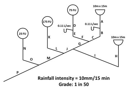
| A (Leader) | 10m × 15m = 150 m² 150m² × 10 mm/15 min = 1,500L/15 min 1,500L/15 min on Table 2.4.10.11 = 2″ leader |
|---|---|
| B (Leader) | Trap size: 0.11 L/sec on Table 2.4.10.12 = 2″ trap Load from trap = 0.11 L/sec × 900 = 99 L/15 min 99 L/15 min + 1,500 L/15 min = 1,599 L/15 min 1,599 L/15 min on Table 2.4.10.11 = 2″ leader |
| C (Storm building drain) | 1,599 L/15 min @ 1/50 grade on Table 2.4.10.9 = 3″ ST.BD |
| D (SOWS) | 75 FU on Table 2.4.10.6.-A (centre column) = 3″ |
| E (SOWS) | Trap size: 0.11 L/sec on Table 2.4.10.12 = 2″ trap Load from trap = 0.11 L/sec × 31.7 = 3.5 FU (rounded up to one decimal) 3.5 FU + 75 FU = 78.5 FU 78.5 FU on Table 2.4.10.6.-A (centre column) = 3″ SOWS |
| F (Sanitary building drain) | 78.5 FU on Table 2.4.10.6.-C @ 1/50 grade = 4″ SBD |
| G (Combined building drain) | Stormwater: 1,500 L/15 min (from “A”) “Unconverted” FU = 75 (from “D”); use 2,360 L/15 min Semi or cont flow from traps: 0.22 L/sec × 900 = 198 L/15 min Total flow: 1,500 + 2,360 + 198 = 4,058 L/15 min 4,058 L/15 min on Table 2.4.10.9 @ 1/50 grade = 4″ CBD |
| H (Leader) | 10m × 15m = 150 m² 150 m² × 10 mm/15 min = 1,500 L/15 min 1,500 L/15 min on Table 2.4.10.11 = 2″ leader |
| I (Storm building drain) | 1,500 L/15 min on Table 2.4.10.9 @ 1/50 grade = 3″ St. BD |
| J (Combined building drain) | Stormwater: 3,000 L/15 min (from “A” and “H”) “Unconverted” FU = 75 (from “D”); use 2,360 L/15 min Semi or cont flow from traps: 0.22 L/sec × 900 = 198 L/15 min Total flow: 3,000 + 2,360 + 198 = 5,558 L/15 min 5,558 L/15 min on Table 2.4.10.9. @ 1/50 grade = 4″ CBD |
| K (SOWS) | 175 FU on Table 2.4.10.6.-A (centre column) = 4″ SOWS |
| L (Sanitary building drain) | 175 FU on Table 2.4.10.6.-C @ 1/50 grade = 4″ SBD |
| M (Combined building drain) | Stormwater: 3,000 L/15 min (from “A” and “H”) “Unconverted FU = 250 (from “D” and “K”); use 2,360 L/15 min Semi or cont flow from traps” 0.22 L/sec × 900 = 198 L/15 min Total flow: 3,000 + 2,360 + 198 = 5,558 L/15 min 5,558 L/15 min on Table 2.4.10.9 @ 1/50 grade = 4″ CBD |
| N (SOWS) | 25 FU on Table 2.4.10.6.-A (centre column) = 3″ SOWS |
| O (Sanitary building drain) | 25 FU on Table 2.4.10.6.-C @ 1/50 grade = 3″ SBD |
| P (Combined building drain) | Stormwater: 3,000 L/15 min (from “A” and “H”) “Unconverted” FU = 275 FU; 275 x 9.1 = 2,502.5 L/15 min Semi or cont flow from traps: 0.22 L/sec x 900 = 198 L/15 min Total flow: 3,000 + 2,502.5 + 198 = 5,700.5 L/15 min 5,700.5 L/15 min on Table 2.4.10.9 @ 1/50 grade = 4″ CBD |
The steps to take note of in the example above are:
- Although the two traps have the same flow rate into them in L/sec and are sized from the same table using that flow rate, the load from them is dependent upon the pipe that they are draining through, which is expressed in L/15 min for storm or combined pipes and in FU for sanitary pipes
- The loads at “J” and “M” are the same, even though there are 175 FU more at “M” than at “J”. This is because we look for the total number of FU going through a combined building drain. At “G”, “J” and “M” the load from “unconverted” (original) FU had not yet reached or exceeded 260, so at those points the single conversion number of 2,360 L/15 min was used to represent them. At “P”, there were now more than 260 FU in that piece of combined building drain, so instead of using 2,360 L/15 min we now multiply the “unconverted” FU by 9.1 and use that number. It is an “either/or” situation when considering the load presented on a piece of combined building drain by fixture units; either 2,360 L/15 min or FU x 9.1, never both.
- Never include the converted FU from any semi or cont flow trap in the calculation for a combined building drain. Instead use the calculation “L/sec x 900 = L/15 min”
- Don’t take shortcuts in calculations of load on combined building drains! Whenever a new piece of combined building drain is to be sized, always look for the totals of the three possible types of flow going through it, which are:
- Stormwater from roof drains and parking lot drains
- “Unconverted” (original) FU, and
- Semi or continuous flow from traps serving pumps or clear water waste
Also remember that a clearwater waste fixture or appurtenance can drain into either a sanitary pipe or a stormwater pipe, and that pipe will still retain its name. A combined building drain or sewer is only so named because stormwater and sewage exist within the same pipe.
The table below shows the three varieties of building sewers, the NPC table used to size them and the units of measurement of flow within them.
| Sewer Type | Table | Units of Measure |
|---|---|---|
| Sanitary | 2.4.10.6.C | Drainage Fixture Units |
| Storm | 2.4.10.9 | L/15 minutes |
| Combined | 2.4.10.9 | L/15 minutes |
Grades
Proper slope of gravity sewer pipes is important so that liquids flow smoothly, which helps transport solids away without clogging. A pipe that is installed at too shallow a grade will prevent waste from being carried along, which will no doubt result in blockages. It is also commonly thought that pipes that are too steep will allow liquids to flow so quickly that solids will not be carried away at that same velocity, also contributing to blockages. This concept has endured much debate over many decades, and the resulting train of thought has been that, for optimum performance, installers should strive to provide a minimum grade of 2% (approximately ¼”/ft) on any horizontal drainage pipe, regardless of its designated name (e.g “branch” or “sanitary building drain”) or function. Short sections of nominally vertical pipe are unavoidable in most installations but maintaining all nominally horizontal pipe as close to this grade as possible appears to work best.
Now complete Self-Test 2 and check your answers.
Self-Test 2
Self-Test 2
- Where do the National and BC Plumbing Codes have application jurisdiction?
- On all properties everywhere in Canada
- On public property underground only
- On private property only
- On public property only
- What were the original calculations for a fixture unit based on?
- 1 ft³ of water through a 1 ¼″ ID pipe in 1 minute
- 1 ft³ of water through a 1 ¼″ OD pipe in 1 minute
- 1 ft³ of water through a 1 ½″ OD pipe in 1 minute
- 1 ft³ of water through a 1 ½″ ID pipe in 1 minute
- What are the units of measure used to size pipes in a storm or combined system?
- Fixture units
- Litres per 15 minutes
- Fixture units per second
- Fixture units per 15 minutes
- Where would one look to find the local rainfall intensity for a city or area?
- BC Plumbing Code
- The Weather Channel
- National Building Code of Canada
- National Plumbing Code of Canada
- What information would one consult if calculating the discharge rate from flow control roof drains?
- The NPC
- The NBC
- The CBC
- The manufacturer
- What are the units of measure used to size pipes in a sanitary system?
- Fixture units
- Litres per 15 minutes
- Fixture units per second
- Fixture units per 15 minutes
- What is the conversion factor to be used to represent the flow through a combined building drain from not more than 260 fixture units?
- 9.1 litres per 15 minutes
- 900 litres per 15 minutes
- 9.1 litres/15 min per L/sec
- 2,360 litres per 15 minutes
- Which one of the following choices would be the correct conversion of 300 FU flowing through a combined building drain?
- 900 L/15 min
- 2,360 L/15 min
- 2,730 L/15 min
- 9,510 L/15 min
- If a fixture discharging clearwater waste drains into a sanitary building drain, what is that pipe now called?
- A branch
- A fixture drain
- A sanitary building drain
- A combined building drain
- What is the most common grade for above ground and below ground nominally horizontal drainage pipes, which helps ensure that solid waste will be carried away by the liquid flow?
- 0.5%
- 1%
- 2%
- Greater than 2%
Check your answers using the Self-Test Answer Keys in Appendix 1.
Media Attributions
- Figure 1 Semi or continuous flow fixture into a sanitary system vs a storm system adapted from image by ITA is licensed under a CC BY-NC-SA licence.
- Figure 2 Sample load conversion by Greg Wirachowsky is licensed under a CC BY-NC-SA licence.
