Learning Task 3
Describe the Installation of Manholes
NPC Code Requirements for Manholes
The following are references from the NPC regarding manholes:
- 2.2.5.2.(5) – Concrete Pipe and Fittings: Precast reinforced circular concrete manhole sections, catch basins and fittings shall conform to CSA A257.4, “Precast Reinforced Circular Concrete Manhole Sections, Catch Basins and Fittings”
- 2.4.7.1.(4) – Where a cleanout is required on a building sewer 8 inches or larger in size, it shall be a manhole.
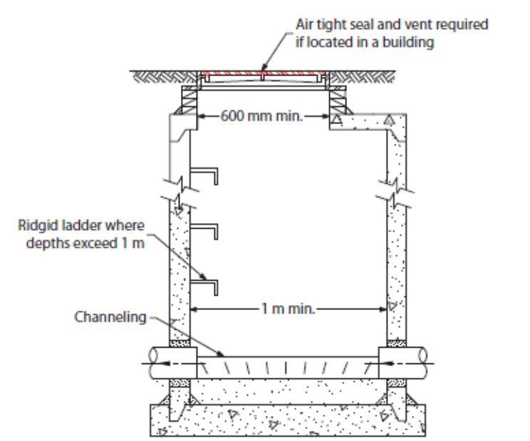
- 2.4.7.3 “Manholes”:
- A manhole, including the cover, shall be designed to support all loads imposed upon it.
- A manhole shall be provided with
- a cover that provides an airtight seal if located within a building
- a rigid ladder of a corrosion-resistant material where the depth exceeds 1m, and
- a vent to the exterior if the manhole is located within a building
- A manhole shall have a minimum horizontal dimension of 1m, except that the top 1.5m may be tapered from 1m down to a minimum of 600 mm at the top.
- A manhole in a sanitary drainage system shall be channeled to direct the flow of effluent.
Manhole Installation
The following instruction points are typical of those found in contract documents that apply to a general or mechanical contractor installing manholes and catch basins onsite.
Delivery, Handling, and Storage
- Once the concrete sections have been delivered to site the installer must inspect the components for damage during shipping and unloading, and any non-compliance to approved shop drawings.
- Manhole components shall only be handled with appropriately rated handling equipment from the safe lift points designated by the manufacturer of the precast manhole sections. Manhole ladders, steps or appurtenances are not to be used as lifting points.
- When lifting manhole bases and risers, make sure the chain or cable lengths are long enough to prevent contact with the manhole joint area and are kept at appropriate lifting angles. Where safe lifting angles cannot be achieved, use appropriately rated spreader bars.
- If manhole product(s) need to be stored onsite, it is the installer’s responsibility to ensure the product is placed on level ground and free from unnecessary mud or debris to prevent damage to the manhole components.
- If any damage or non-compliance is identified, the installer shall take corrective action by notifying the manufacturer. Upon inspection if the damage may affect the performance of the manhole structure, the area shall be repaired. If the damaged manhole component cannot be repaired that component shall not be installed.
- If furnished, special joint materials, such as gaskets, lubricant, and mastic shall be stored securely and in accordance with manufacturer’s recommendations.
Excavation and Bedding Preparation
- Shoring if utilized for construction shall be in accordance with all national, regional, and local regulations.
- If shoring is to be removed, the installer shall use the appropriate lifting equipment to safely remove the shoring and to prevent any disturbance or damage to the manhole.
- The manhole foundation should be moderately firm to hard stabilized soil, or compacted fill material with adequate bearing capacity to support the manhole structure.
- A minimum 3 inches [75 mm] thick leveling course shall cover an area not less than manhole base area but preferably 6 inches [150mm] beyond the outside radius of the manhole base. The nominal maximum aggregate size within the leveling course shall not be greater than 1 inch.
- The soil foundation area or bedding under incoming and outgoing pipes should be treated the same as the manhole base section to prevent settlement or shearing of pipes and to provide proper alignment for the watertight connector/pipe interface if resilient rubber connectors are being used.
Installing and Joining
- During installation, set the manhole base on the leveling course making sure the manhole base section is firmly in place and the connectors or pipe openings match design orientation. Verify the top of the manhole base is level in two directions perpendicular to each other.
- Verify the manhole base section pipe openings and/or connectors are at proper grade for pipe inverts to match design elevations.
- Assemble multi-section manhole structures by lowering each section into the excavation. As they are installed, verify each additional riser section is plumb and the joint homed before installing the next riser, conical top or flat slab top.
- Ensure any seals or gaskets are installed correctly. The graphic below shows three common types of manhole rubber seals.
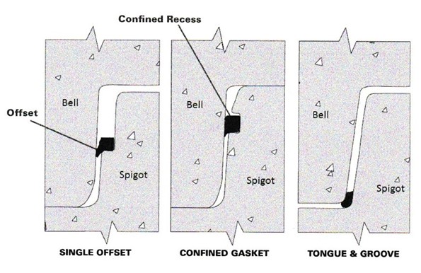
Figure 2 Manhole section seals - Adjacently placed manhole sections shall be aligned to match the step placement of the preceding section if steps are provided.
- To ensure joint integrity when assembling the manhole structure, the installation contractor is responsible to maintain clean joint surfaces, removing all foreign materials that could damage or impair the jointing surfaces or gasket materials.
Connecting Pipes to Manholes and Field Cutting or Coring
- Any field cut of the manhole structure required for a pipe opening shall be approved by the engineer
- Lifting holes (full penetration “see through”) shall be sealed by inserting into the hole a rubber or plastic plug, precast plug with mastic sealant or with an approved cementitious material (or filling the opening with non-shrink grout from inside or outside or both).
- Embedded or cast-in lift anchors (“non-see through”) shall have the exposed small pocket volumes filled with non-shrink grout or with an impervious mastic material.
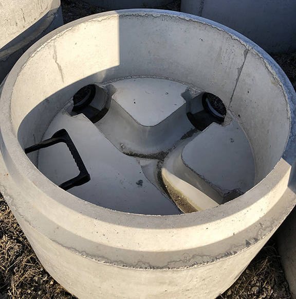
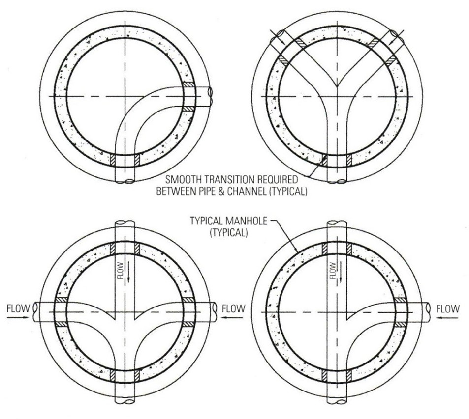
Channeling and Benching
Channels are created at the base of sanitary manholes to eliminate free-fall conditions resulting from invert elevation differentials between incoming and outgoing pipes. The areas surrounding the channels are called benches. There are several methods used by precast manufacturers or contractors to create invert channels in precast concrete manholes. They include installation at the plant and field installation. To ensure the best quality product, inverts should be manufactured in the precast plant along with the manhole section, cured, and then delivered to the site. However, there are specific instances when pouring of inverts must be done in the field, and this situation is the norm. The following precautions should be followed.
Field-Poured Manhole Benching
- For precast manhole bases, the area underneath the manhole base must be excavated to the required elevation. The soil below the base should not be disturbed, or if fill is required it should be properly compacted. The manhole base is then lowered into the trench and checked for proper bearing on the sub-grade, proper elevation, and orientation to receive the incoming and outgoing sewers at the designated invert elevation. The base should be set to the invert elevations specified on the plans. If the base is not set within plan specifications, it may have to be removed and reset.
- The concrete inverts will be formed after connecting the sewer pipes to the manhole. The invert must be true to the sewer pipe invert elevations, with smooth channels of uniform cross section and slope, either straight or with a continuous curve between the inlet and outlet of the pipes. The concrete invert should be placed based on the dimensions and details of the contract plans and specifications. Some installers use dirt, brick, and other loose material as the foundation of the invert and then add a thin coat of concrete on the surface. This method should not be used because it does not produce a durable invert, which could lead to future maintenance problems.
- As with invert channels manufactured at the plant, field-poured channels and benching must be constructed only with high-quality concrete. The channels should then be consolidated, finished, cured, and properly placed. The minimum concrete thickness must be 2 inches.
- For onsite-constructed channeling, some installers use pipe of the same dimensions as the intended channel as the form for the channel. The pipe is coated with form oil and pressed halfway into the concrete benching to create a uniform path. The pipe is then removed, and the channel is troweled to a smooth finish.
Backfilling and Restoration
- Excavations shall be backfilled with an approved or specified soil material free from large stones, rocks, pavement, and other items that could damage the installed manhole structure. Expansive soil material shall not be used as backfill around the structure.
- When a precast concrete manhole structure is placed in an unpaved area, slope the area around the entrance frame and cover to provide drainage away from the entrance cover. Slope the final grading upward to within 1 inch (25 mm) of the top surface of the frame and cover.
- Backfilling shall be achieved by using lifts (layers) and compaction efforts or flooding (jetting) the excavation to meet the required soil density requirements.
- The installer must take special care and placement of bedding and backfill material under and surrounding pipe connections to manholes to provide firm, uniform support of the pipe at these junctions. This compaction effort is to reduce the potential of pipe shear at the manhole interface due to differential settlement of the surrounding soil.
Media Attributions
- Figure 1 Concrete sanitary manhole by ITA is licensed under a CC BY-NC-SA licence.
- Figure 2 Manhole section seals © photo courtesy of the National Precast Concrete Association.
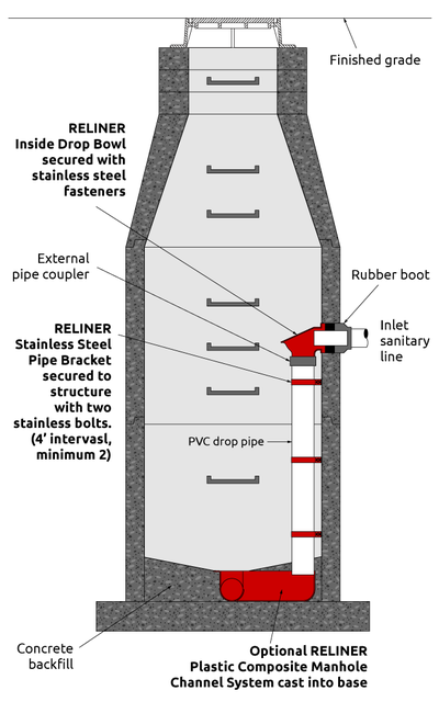
- Figure 3 Manhole components © Reliner, used with permission.
- Figure 4 Precast channeling © Kohnen Concrete Products, Inc. Used with permission.
- Figure 5 Examples of suggested directional changes through a manhole © photo courtesy of the National Precast Concrete Association.
