Sim Labs
Objective
| To operate the MC-90 ship model fully loaded on “At sea” mode and use Indicator cards to accurately predict the cause of deviation in the operational parameters of the main Engine and suggest appropriate corrective action. The student would be required to inject the various malfunctions in sequential order and at any deviation of Exhaust temperature take a set of indicator cards and analyze them to suggest corrective action. The following common malfunctions need to be injected in sequential order, indicators cards taken, analysed and corrective action outlined, as shown in the attached example:
|
Theory
Indicator cards
The Marine Engineer Officer of the Watch, during his watch, must ensure that the Main propulsion engine is performing at its optimum level. This will not only reduce the fuel consumption for a given voyage, but also reduce maintenance requirements and down time.
There are various methods by which this can be achieved, namely:
- Trend analysis
- Indicator cards
The Trend analysis of engine performance has been traditionally used for a number of years by marine engineers to identify the malfunctioning component by comparing the observed engine parameters with shop test parameters. Example of some of the parameters compared are:
- Exhaust temperatures
- Fuel rack setting.
- T/C revs
- scavenge pressure
- Pressure drop across scavenge coolers and T/C air filters
- Temp & pressure of fuel input
The cylinder indicator cards are used as a teaching aid and diagnostic tool to allow regular monitoring of the engine cylinders. Using indicator cards, faults within the combustion system can be accurately identified allowing the engineers to take the safe corrective action.
There are three different displays that are recorded to indicate the cylinder pressure conditions:
1. pressure/angle (also called a draw card or out of phase diagram),
2. pressure/volume (also called a power card, or in-phase diagram), and
3. the weak spring diagram,
Each diagram can be used to illustrate differing combustion traits and combustion malfunctions. Example: The pressure/angle diagram would be used to:
- Indicate cylinder sealing efficiency by comparing the compression pressure curve of one cylinder with the other cylinders
- Display the approximate timing of the fuel ignition
- Display the fuel pressure trace
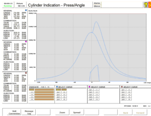
At the instant when the cylinder indicator is taken, the following parameters are displayed on the left hand side, in the numeric data display,
Speed – the engine RPM (N).
Index – measure of the fuel index
MIP – Mean Indicated Pressure (MIP) measured in bar. This pressure is the equivalent pressure that acts on the piston throughout its vertical power stroke.
IkW – Indicated Power of the cylinder
TIGN – Is the timing of the ignition. The time between the TINJO and TIGN indicates the ignition delay present for that cycle. Increasing ignition delays will cause increased PMax and large delta pressure/angle (dP/da)
PMax – is the maximum pressure present during the working cycle. This will be affected by the quantity and timing of the fuel injection.
TMax – Is the maximum temperature during the working cycle.
PCOMPR – Is the compression pressure after the compression stroke. It provides valuable information to the sealing efficiency of the piston rings, liner, and cylinder cover valves.
PINJO – Is the fuel pressure when the fuel injector opens. It provides useful information about the correct functioning of the fuel injector.
PINJM – Is the maximum fuel pressure generated by the fuel pump which indicates the internal sealing properties and internal wear of its components.
TINJO – Is the timing of the fuel injection and any deviation from normal values indicates shift of the cam.
LINJ – Is the length of the fuel injection period, and is dependent on the setting of the fuel control lever.
Example of recorded images for an Engine with sticking piston rings in Cylinder #1 :
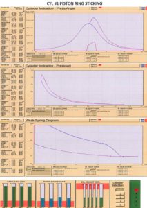
Observation summary:
- Ring movement – reduced from 90 to 40
- Ring sealing unchanged
- No deviation in Exhaust gas temperatures
- No change in the profile of all the Indicator cards of Unit #1
- No change in the profile of all indicator cards when comparing Unit #1 with Unit #2
Corrective action:
- Monitor Main engine parameters , do not reduce main engine RPM
- Inform Chief Engineer and slightly increase cylinder lubrication of the unit with sticking piston rings
- At first opportunity overhaul the unit
