Part 2 – Generating 3D Maps
Chapter 2.3 – Orthomosaics
Overview
Once an accurate digital surface model (DSM) or digital terrain model (DTM) is created, it can be used along with the original air photos to create an orthophoto mosaic or simply orthomosaic.
Orthophoto Mosaic
An orthophoto mosaic, or simply an orthomosaic, is in some ways similar to the texture applied onto the 3D mesh surface. However, instead of the photos being distorted and warped to fit the surface, in orthomosaic generation, the photos are corrected for radial and elevation distortions and then stitched together along seam lines.
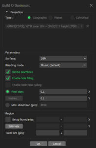
From the Workflow menu, select Build Orthomosaic…. The dialogue box settings are described below.
Projection Type is fixed based on that of the surface (DEM or Mesh, if available).
Surface can either be the DEM or Mesh. Both contain accurate elevation information but since the input photos and output orthomosaic are both in raster format, it is suggested that DEM is used as the input surface.
Blending mode can be set to Mosaic (default), Average or Disabled. The default Mosaic mode is recommended.
Refine seamlines allows the software to adjust the lines along which the overlapping photos are stitched together in order to avoid photo edges and elevated areas such as buildings or trees.
Enable hole filling closes any small gaps that may be present in the surface.
Enable back-face culling is enabled only when the surface type is set to Mesh. This allows the “inside” faces to also show the mosaic colors.
Pixel size (m) allows the user to specify the output pixel size of the orthomosaic. It is never recommended to set this value lower than the default, though higher values can be used to reduce file size at the expense of detail. This is also useful for matching the resolution of the orthomosaic to external data sets.
Setup boundaries allows the user to adjust the output boundaries of the orthomosaic with the corresponding Total size in pixels.
Fig. 20 below shows the suggested orthomosaic parameter settings.
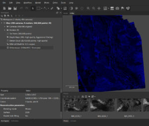
Once the orthomosaic is generated, double-clicking on it in the Workspace pane opens it in the Ortho tab as shown below.
Part 3 describes how to export the orthomosaic from MetaShape to other popular data formats including Google Earth and ESRI ArcMap.
