Part 2 – Generating 3-D Maps
Chapter 2.3 – DEM & Orthomosaic
Overview
Once the textured 3-D mesh is generated, the next step is to create an accurate digital elevation model (DEM), digital surface model (DSM) or digital terrain model (DTM) along with an orthophoto mosaic or simply orthomosaic.
Before proceeding, save the project by accessing the File menu, selecting Save As…, navigating to the BCIT_Field folder and naming the project BCIT_Field.psx.
Building a DEM
A digital elevation model is a raster image (pixels, arranged in rows and columns) with each pixel representing the elevation. If the model represents elevations of the ground along with heights of structures such as buildings and trees, it can be referred to as a digital surface model (DSM). If the elevations only represent the ground or the bare earth, the model is referred to as a digital terrain model (DTM). The general term describing any type of raster elevation surface is digital elevation model (DEM).
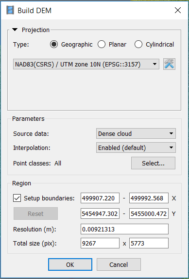
From the Workflow menu, select Build DEM…. The dialogue box settings are described below.
Projection Type can be set according to other data sets that you’d like this DEM to geographically coincide with.
Source data allows a choice between using the Sparse Cloud, Dense Cloud, or Mesh as the source of elevation data. The Sparse Cloud should never be used as it is the least accurate representation of elevation. The main difference between using Dense Cloud or Mesh is that the former is the truest representation of the surface but may have holes or gaps where elevation data may be missing due to sparse alignment between photos. The latter represents a more continuous surface (assuming that interpolation or extrapolation was enabled when building the mesh), keeping in mind that the interpolated elevations are algorithmic guesses based on surrounding known elevations.
Interpolation can be Enabled (default) to fill holes or gaps in elevations, Disabled or an Extrapolation can be applied instead.
Point classes can be selected (if they have been previously created through classification) or All (default) classes will be used.
Region settings can be adjusted if necessary, affecting the output Resolution and Total size of the DEM.
Below are the suggested DEM settings for this project and don’t worry if the Region values are slightly different.
To view the DEM, double-click it in the Workspace pane which brings up a new Ortho tab in the main view.
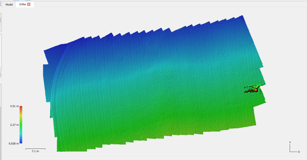
Note that the pixel resolution of the DEM is approximately 9mm. Also notice the lines formed in the grass from the previous position of the goalie net (just to the left of where the goalie net is presently positioned).
Now that an accurate raster representation of the surface is generated, it can be used to create an orthophoto mosaic as described below.
Orthophoto Mosaic
An orthophoto mosaic, or simply an orthomosaic, is in some ways similar to the texture applied onto the 3-D mesh surface. However, instead of the photos being distorted and warped to fit the surface, in orthomosaic generation, the photos are corrected for radial and elevation distortions and then stitched together along seam lines.
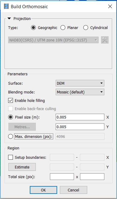
From the Workflow menu, select Build Orthomosaic…. The dialogue box settings are described below.
Projection Type can be set according to other data sets that you’d like this DEM to geographically coincide with.
Surface can either be the DEM or Mesh. Both contain accurate elevation information but since the input photos and output orthomosaic are both in raster format, it is suggested that DEM is used as the input surface.
Blending mode can be set to Mosaic (default), Average or Disabled. The default Mosaic mode is recommended.
Enable back-face culling is enabled only when the surface type is set to Mesh. This allows the “inside” faces to also show the mosaic colors.
Pixel size (m) allows the user to specify the output pixel size of the orthomosaic. It is never recommended to set this value lower than the default, though higher values can be used to reduce file size at the expense of detail. This is also useful for matching the resolution of the orthomosaic to external data sets.
Setup boundaries allows the user to adjust the output boundaries of the orthomosaic with the corresponding Total size in pixels.
The following orthomosaic generation settings are suggested for this project.
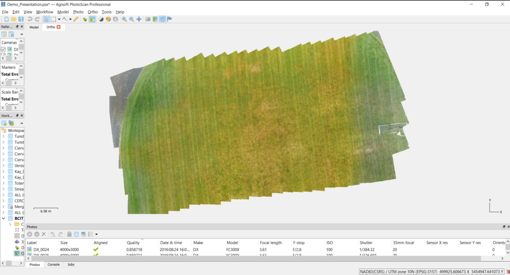
Once the orthomosaic is generated, double-clicking on it in the Workspace pane opens it in the Ortho tab as shown below.
The next Part describes how to export the textured 3-D model, DEM and orthomosaic from Photoscan to other popular data formats including Google Earth and ESRI ArcMap.
