Chapter 3. Advanced Networking
3.1 Captive Portal
Learning Objectives
- Configure VLANs
- Configure captive portal
Prerequisites:
- Setup Zones
- Some interface configuration
- Configuring VLANs on the GNS3 switch
- Knowledge of previous labs
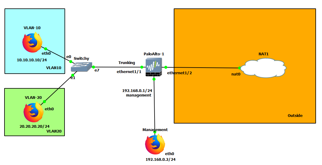
Scenario: Now let’s push for some advanced networking configurations. Sometimes you just have to push departments into their own VLANs for organization and compliance. Say we have a guest and employee network. We want to prevent communication between the two as much as possible. We would also want to implement some sort of login to access the internet for guests, much like hotels.
| Device | Configuration |
|---|---|
| PaloAlto-1 | management: 192.168.0.1/24 Ethernet1/1: Trunking Ethernet1/1.10: 10.10.10.1/24 Ethernet1/1.20: 20.20.20.1/24 Ethernet1/2: DHCP |
| VLAN-10 | eth0: 10.10.10.10/24 GW: 10.10.10.1 DNS: 8.8.8.8 |
| VLAN-20 | eth0: 20.20.20.20/24 GW: 20.20.20.1 DNS: 8.8.8.8 |
| Management | eth0: 192.168.0.2/24 |
| Switchy | e0: Access mode, VLAN 10 e1: Access mode, VLAN 20 e7: dot1q, VLAN 1 |
| Zone | Interface |
|---|---|
| VLAN10 | Ethernet1/1.10 |
| VLAN20 | Ethernet1/1.20 |
| Outside | Ethernet1/2 |
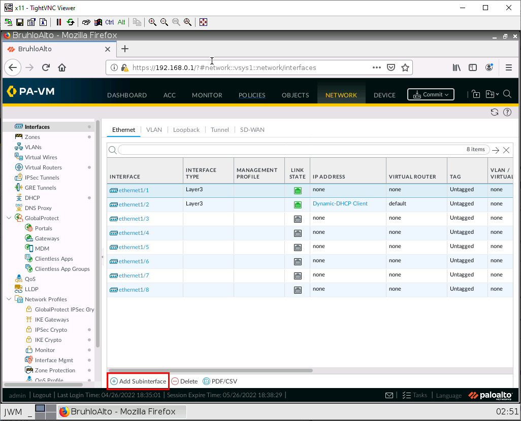
Configure Sub Interfaces
Under Network > Interfaces. Click on ethernet1/1.
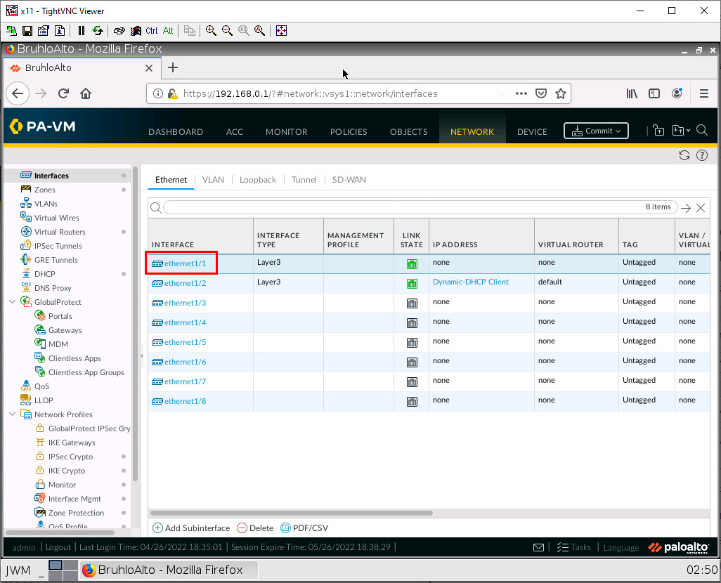
In this window, we just want to set the interface type to layer 3.
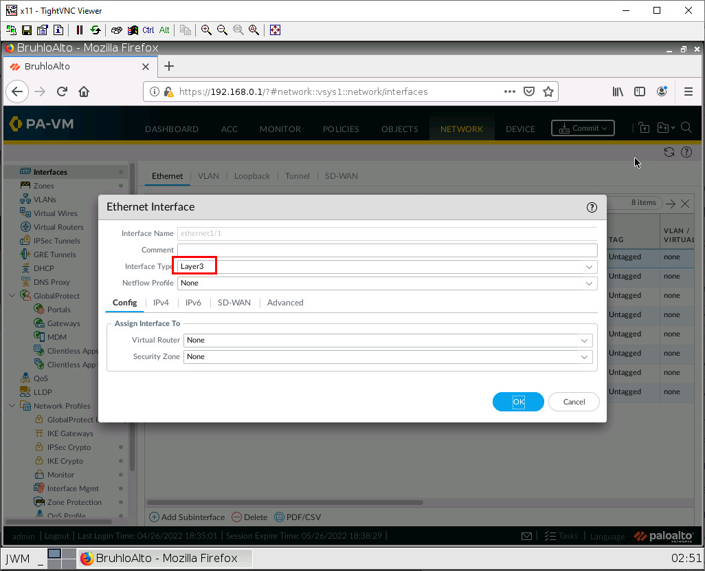
Then press OK.
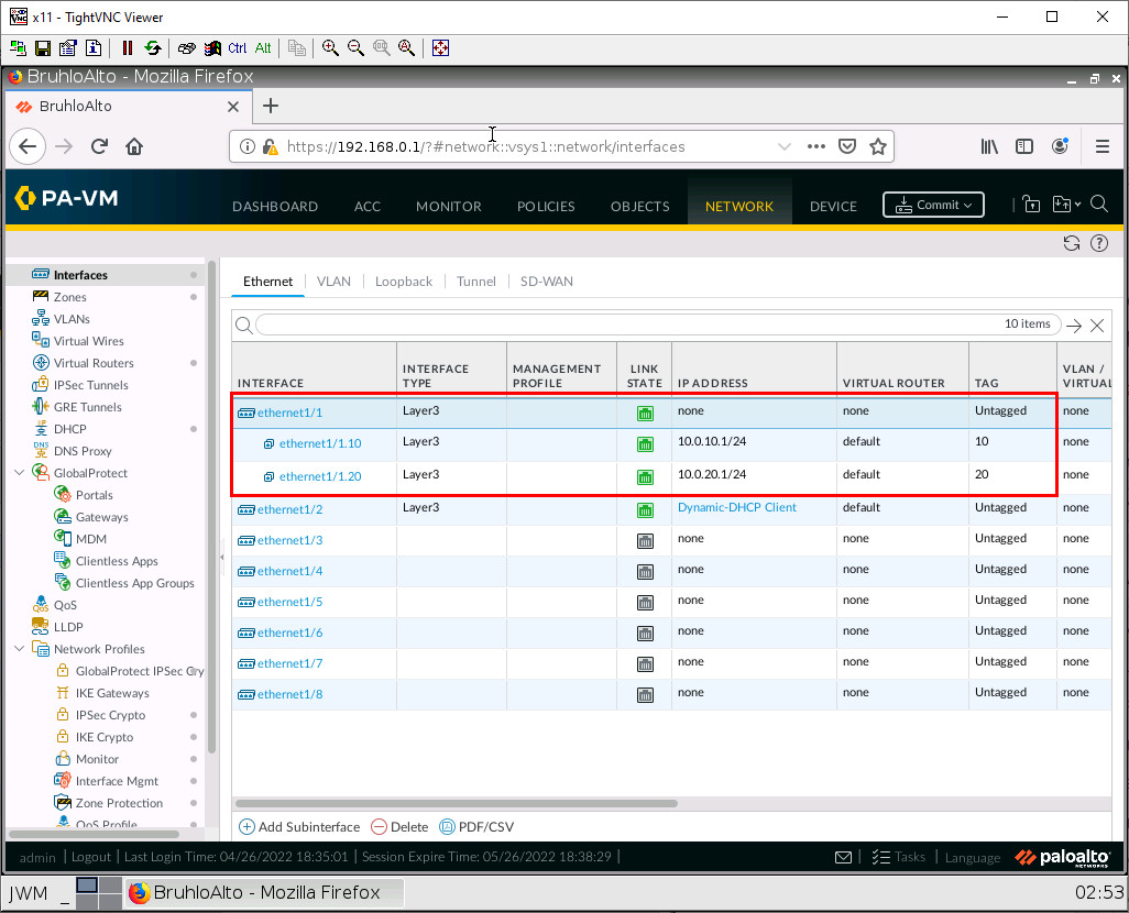
Now while ethernet1/1 is still selected, click on add sub interface.
We want to add 2 sub-interfaces. Here is what you should configure:
| Interface | Configuration |
|---|---|
| Ethernet1/1.10 | Interface Name: 10 Tag: 10 Config tab: – Virtual Router: default – Security Zone: VLAN10 IPv4: – Type: Static – IP: 10.10.10.1/24 |
| Ethernet1/1.20 | Interface Name: 20 Tag: 20 Config tab: – Virtual Router: default – Security Zone: VLAN20 IPv4: – Type: Static – IP: 20.20.20.1/24 |
Semi-Advanced Security Policies
Well, it’s not really advanced, but under Policies > Security, click Add.
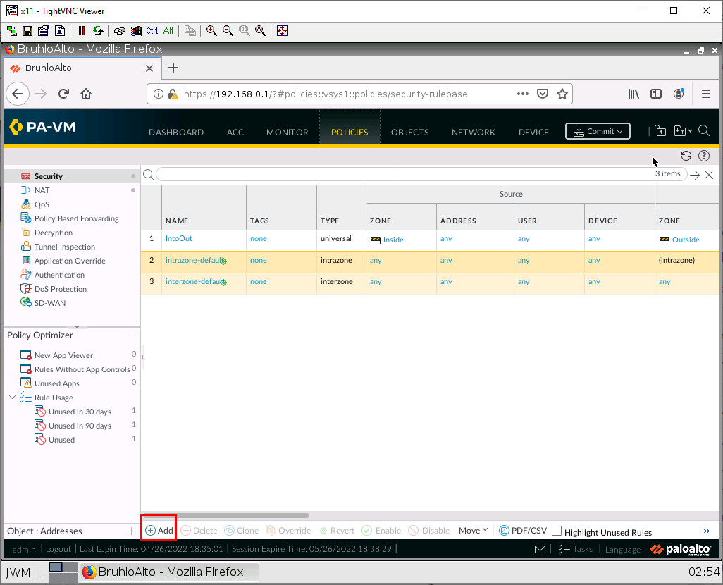
We will be making a policy to allow VLAN10 and VLAN20 into the Outside zone. We can do this by adding multiple zones under the source zone.
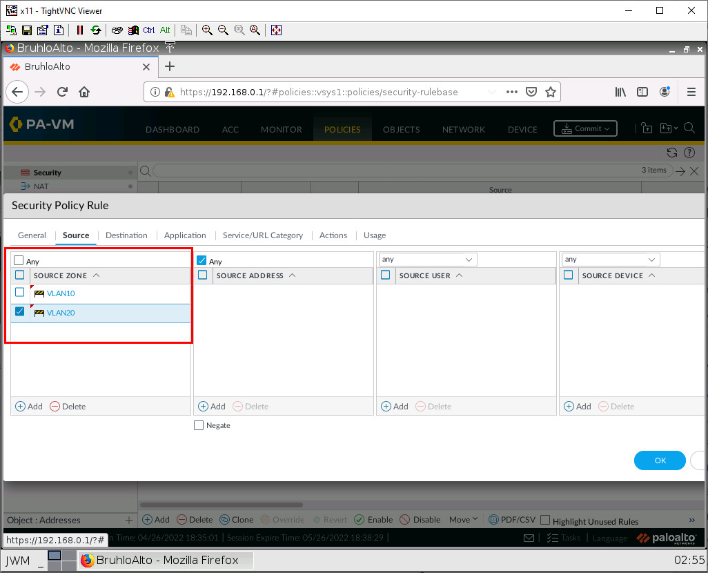
Then click OK.
Semi-Advanced NAT Policies
Still not really advanced. But under Policies > NAT, click Add.
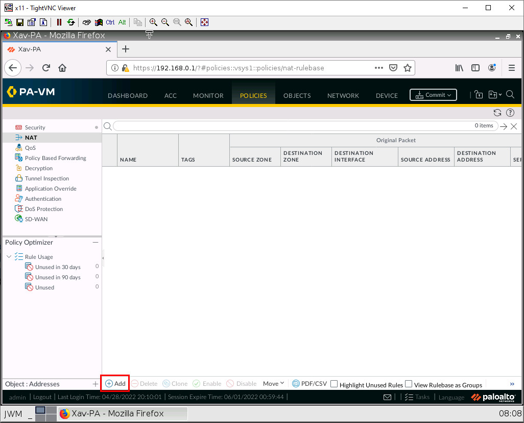
We want to make a Static NAT policy for the Internet connectivity. But under the Original Packet tab, we can select multiple zones.
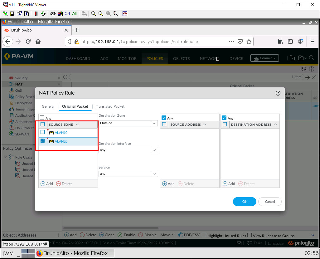
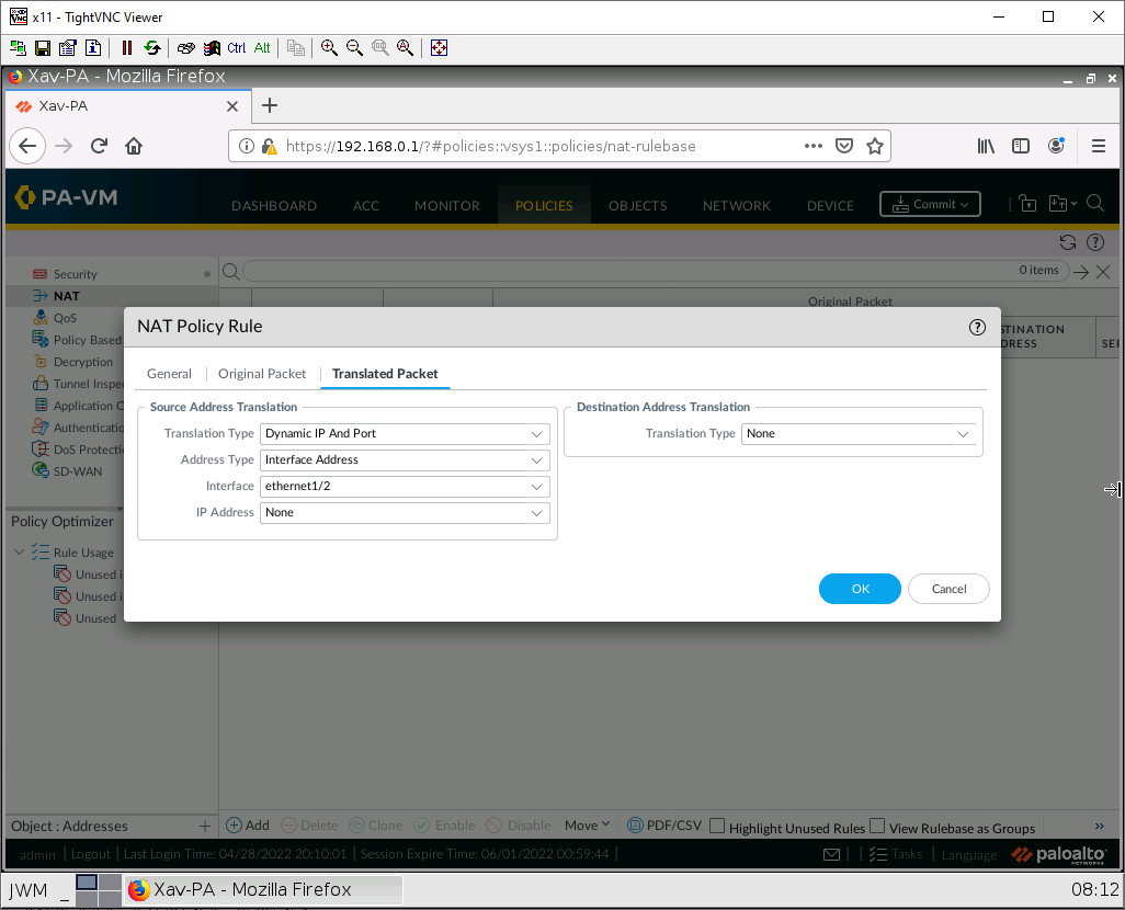
Configure the rest for static NAT, then press OK.
Add a User
Under Device > Local User Database > Users. Click Add.
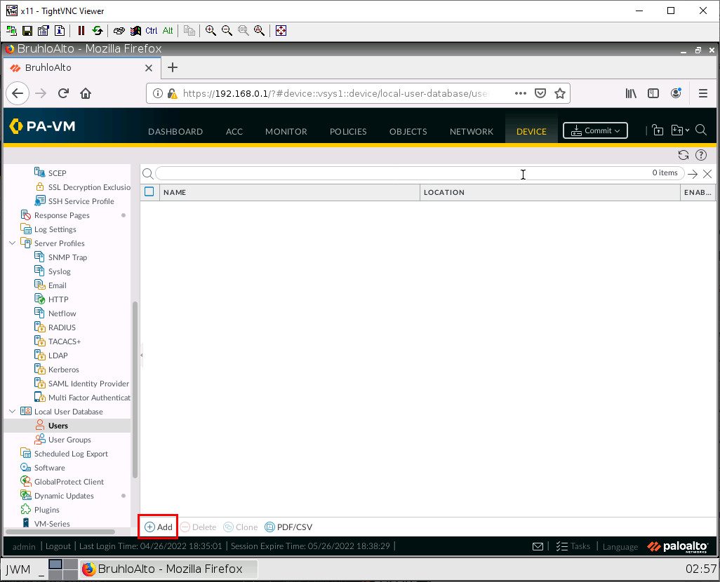
Create any user you want with a username and password. Here is an example:
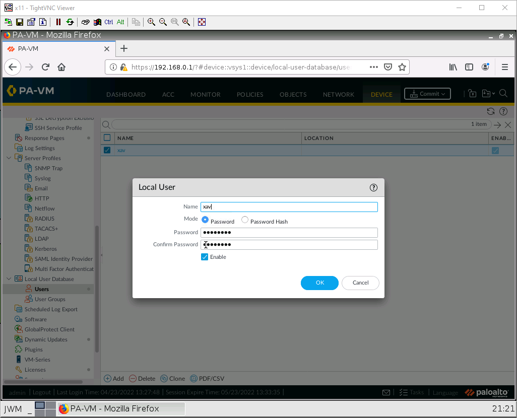
Then click OK.
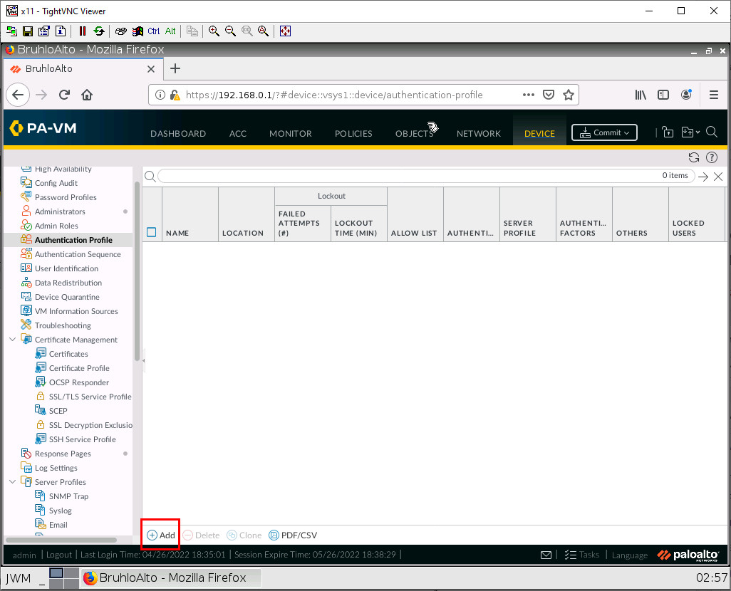
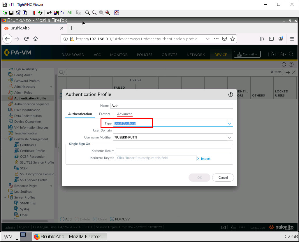
Create an Authentication Profile
Under Device > Authentication Profile, click Add.
Under the Authentication tab, change the type to Local Database.
Under the Advanced tab, add your user.
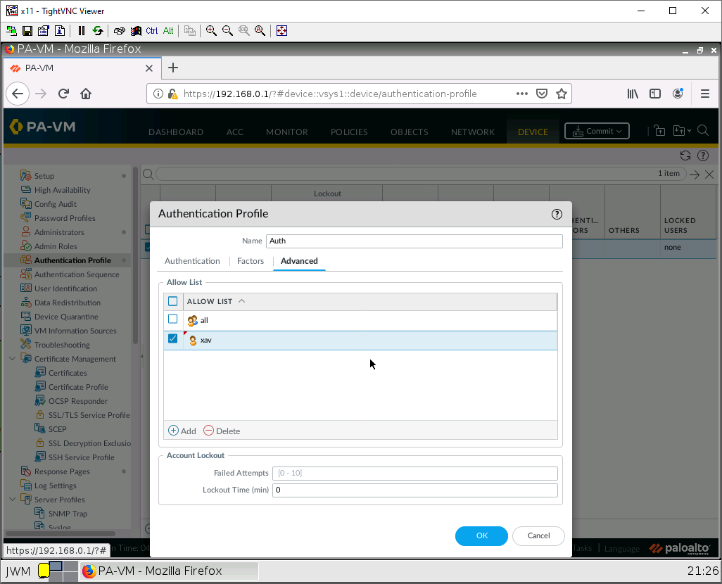
Then press OK.
Configure the Captive Portal
Under Device, User Identification in the Authentication Portal Settings tab, click the settings icon.
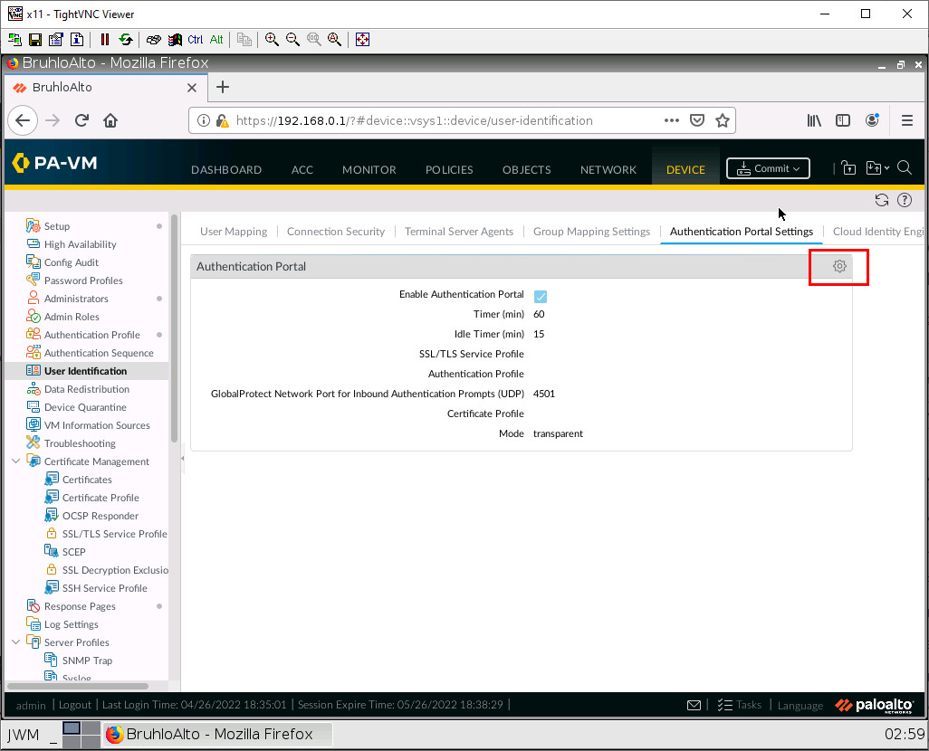
Configure these settings:
| Parameter | Value |
|---|---|
| Enable Authentication Portal | Tick this box |
| Authentication Profile | Select the one you created |
| Mode | Transparent |
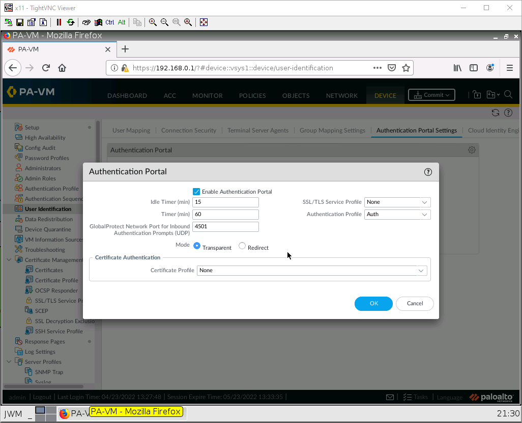
Then press OK.
Under Network > Zones, click on the VLAN10 zone.
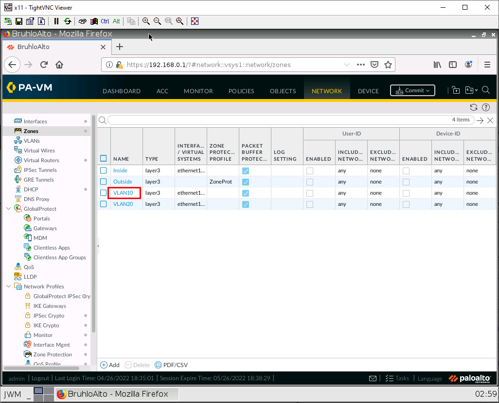
In this window, we just want to tick the Enable User Identification checkbox.
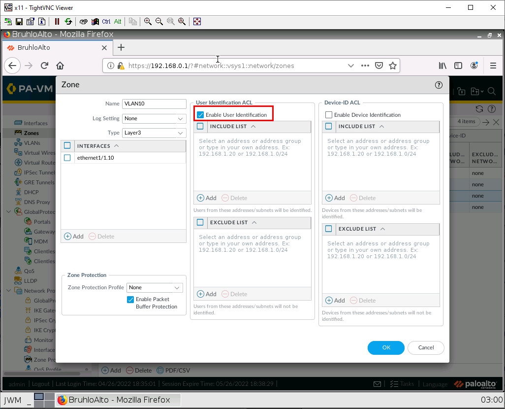
Then press OK.
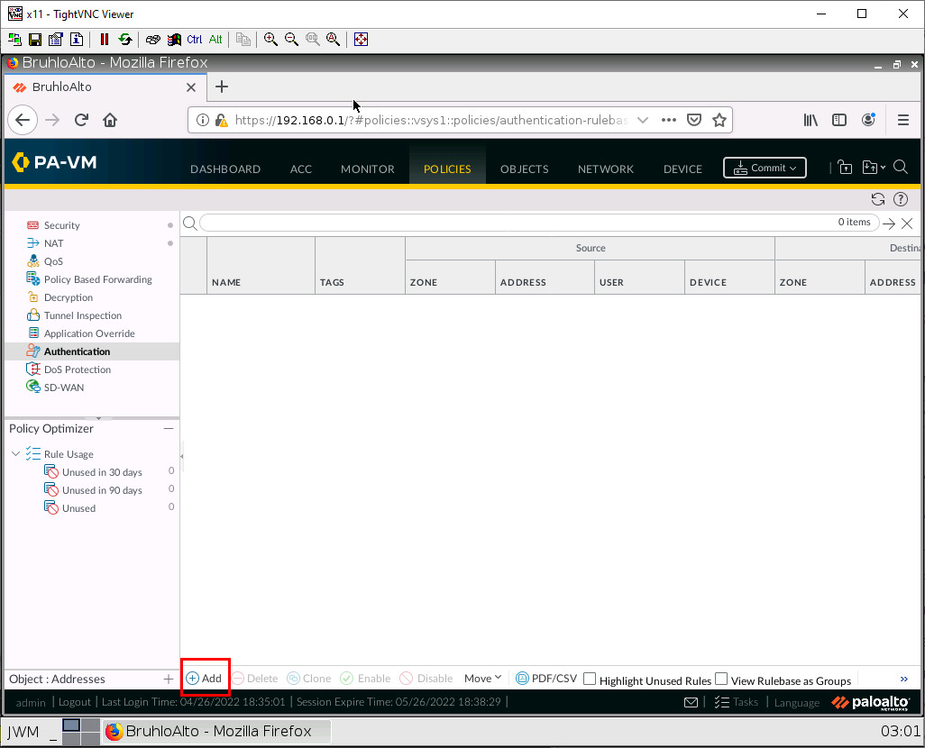
Finally, under Policies > Authentication. Click Add.
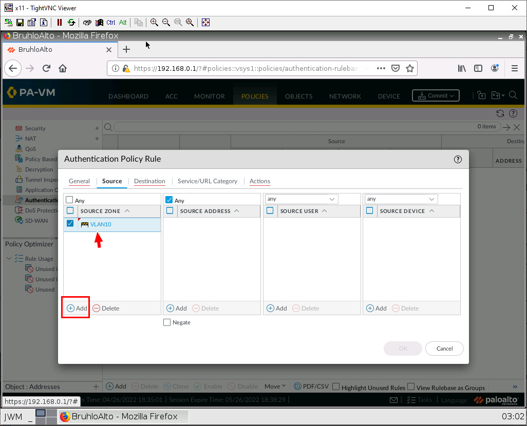
Under the Source tab, add VLAN 10 in the source zone.
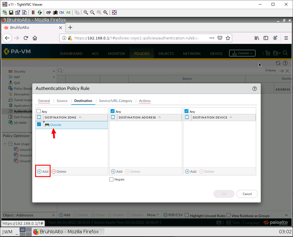
Under the Destination tab, add Outside in Destination Zone.
Under Actions, change the Authentication Enforcement setting, change it to default-web-form.
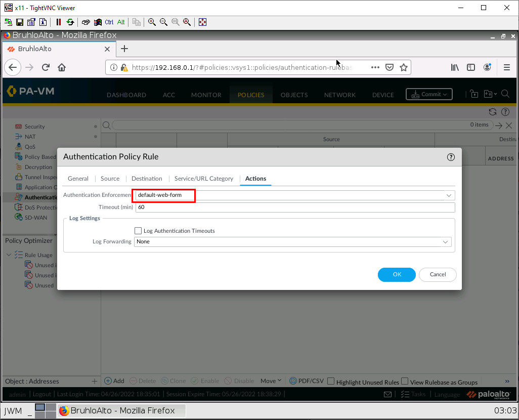
Then press OK.
Test VLANs and Captive Portal
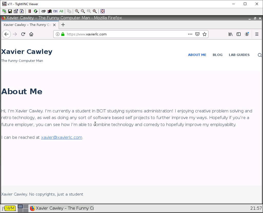
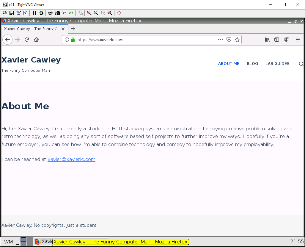
On the VLAN-20 webterm, navigate to any website. If all was right, the desired website should appear.
On the VLAN-10 webterm, navigate to any website. If all was right, you should see a certificate error, accept this. Then you should see a login page.
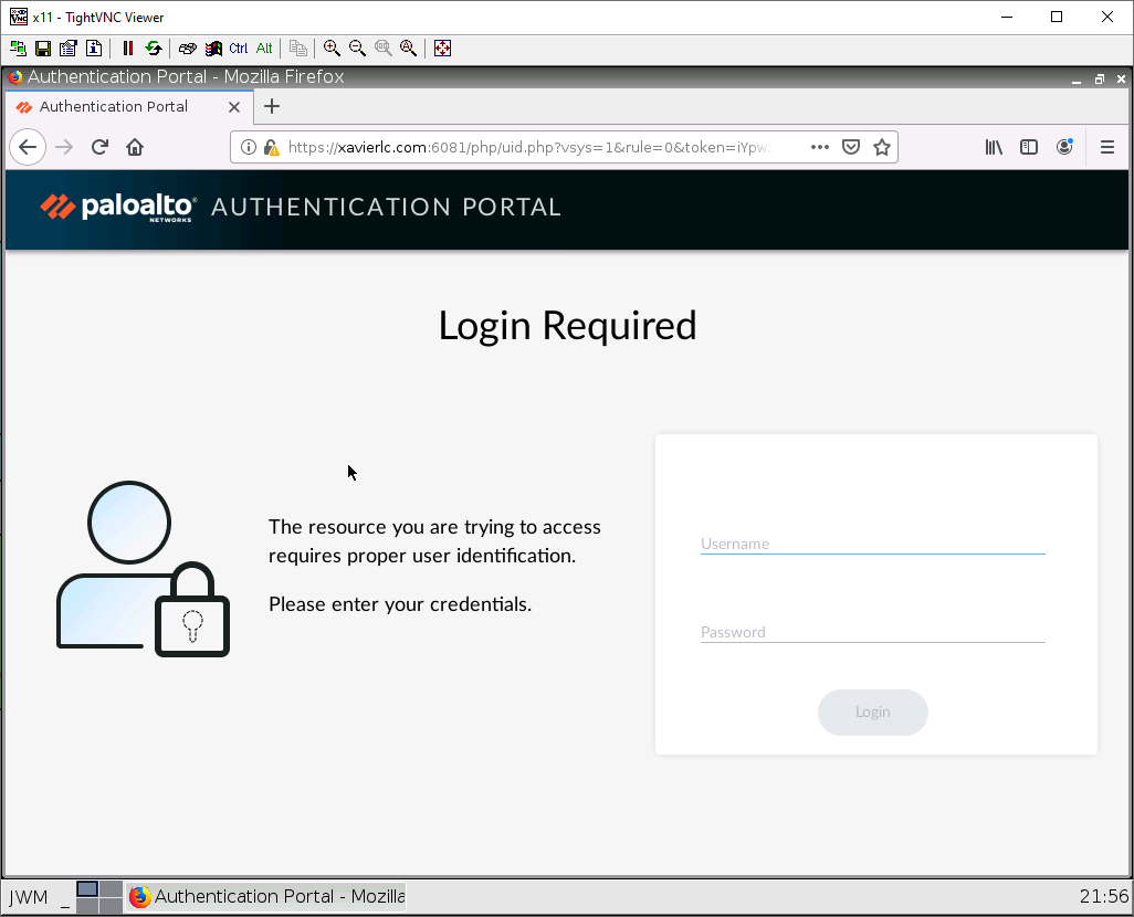
Enter your credentials and log in. If all was successful, you should see the website appear.