Chapter 3. Advanced Networking
3.4 Site to Site VPN PaloAlto, Cisco and FortiGate
Learning Objectives
- Create a tunnel in Cisco router
- Create a tunnel in Palo Alto
- Connect a tunnel from Cisco router to Palo Alto
- Connect a FortiGate tunnel to Palo Alto
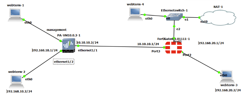
Scenario: We are going to do a site-to-site VPN from Cisco to Palo Alto and then expand it between FortiGate and Palo Alto.
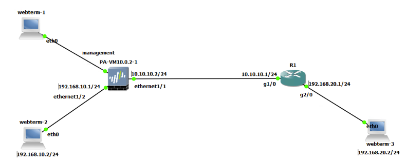
| Device | Configuration |
| Palo Alto | Ethernet 1/1: 10.10.10.2/24 – Type: Layer3
Ethernet 1/2: 192.168.10.1/24 – Type: Layer3 Management: 192.168.0.1/24– Type: Layer3 |
| Router (7200) | G1/0: 10.10.10.1/24
G2/0: 192.168.20.1/24 |
| WebTerm-1 | 192.168.0.2/24 |
| WebTerm-2 | IPV4: 192.168.10.2/24 GW: 192.168.10.1 |
| WebTerm-3 | IPV4: 192.168.20.2/24 GW: 192.168.20.1 |
Zones
| Zones | Interface |
| VPN | Ethernet 1 /1 |
| Trust | Ethernet 1 /2 |
Cisco
- First, configure the router with the following commands:
ip access-list extended Crypto_Acl
permit ip 192.168.20.0 0.0.0.255 192.168.10.0 0.0.0.255


crypto isakmp policy 1
encr aes
hash md5
authentication pre-share
group 5


crypto isakmp key cisco123 address 10.10.10.2
crypto ipsec transform-set TSET esp-aes esp-sha-hmac


crypto map CMAP 10 ipsec-isakmp
set peer 10.10.10.2
set transform-set TSET
match address Crypto_Acl


interface Gi1/0
crypto map CMAP

ip route 0.0.0.0 0.0.0.0 10.10.10.2
Palo Alto
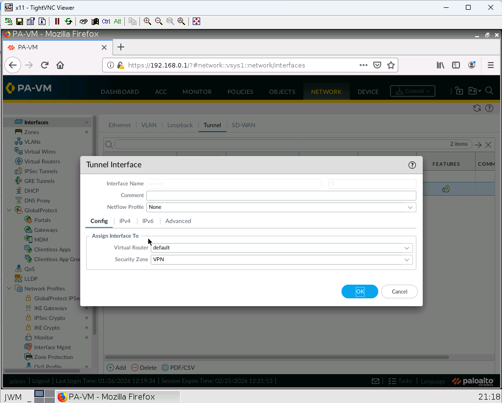
- Create a tunnel and assign the tunnel to VPN Zone
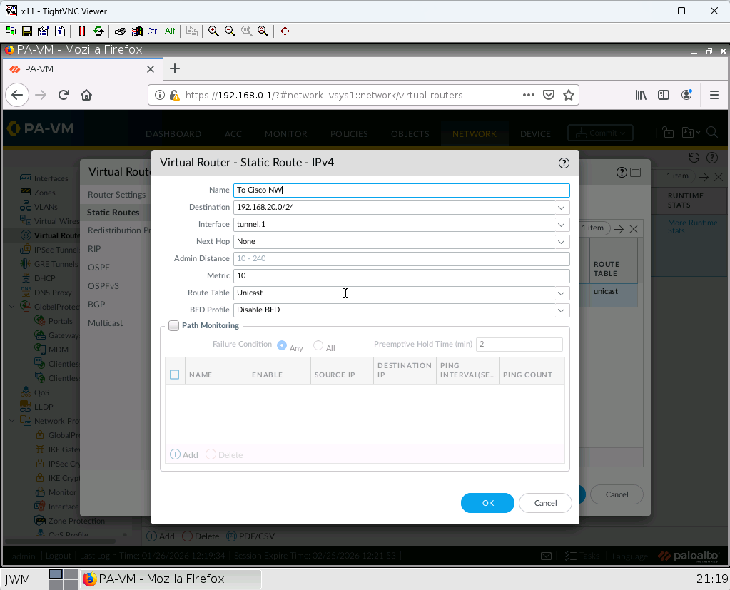
2. Create a static route with following information:
Destination Address: 192.168.20.0/24
Interface: tunnel1
Next Hope: none
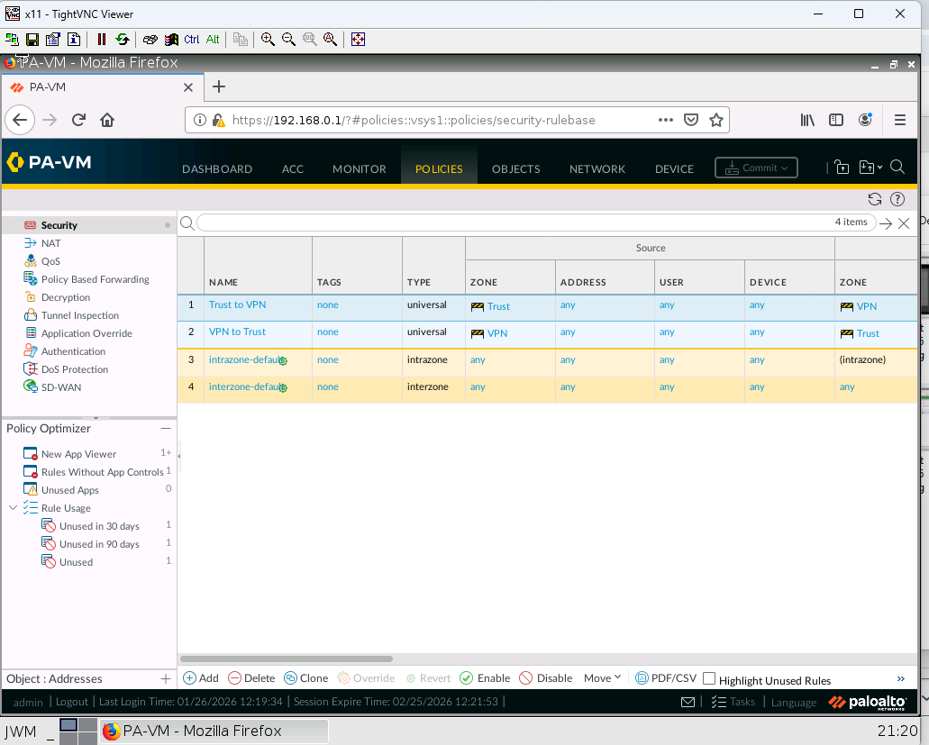
3. Create a Policy that allows the traffic from Trust Zone to VPN Zone and vice versa.
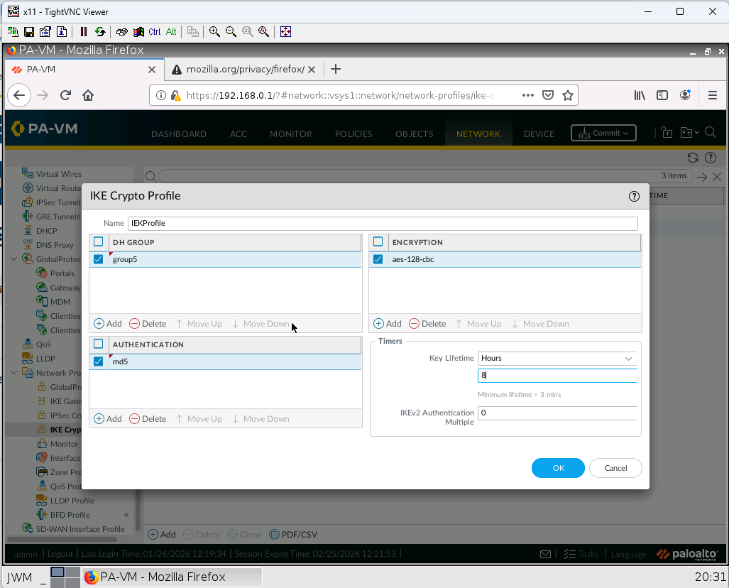
4. Create an IKE profile with following information:
Name: IKEProfile
DH Group: Group5
Authentication: md5
Encryption: aes-128-cbc
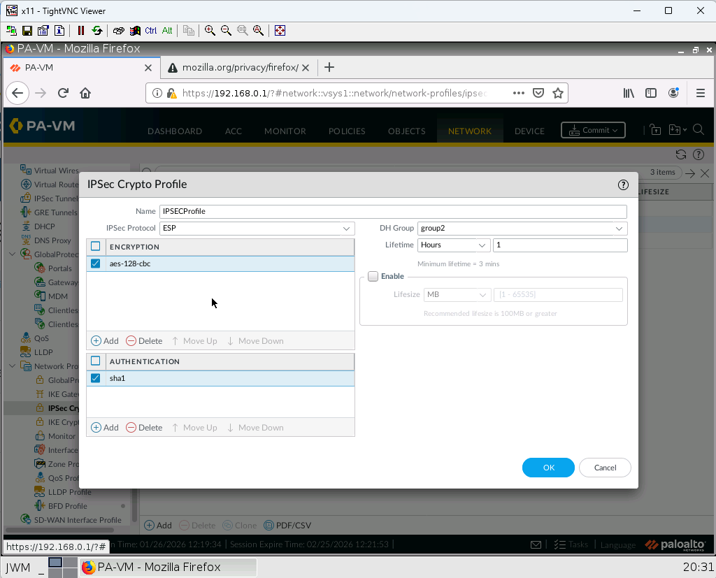
5. Create an IPSEC profile with following information:
Name: IPSECProfile
DH Group: Group2
Authentication: sha1
Encryption: aes-128-cbc
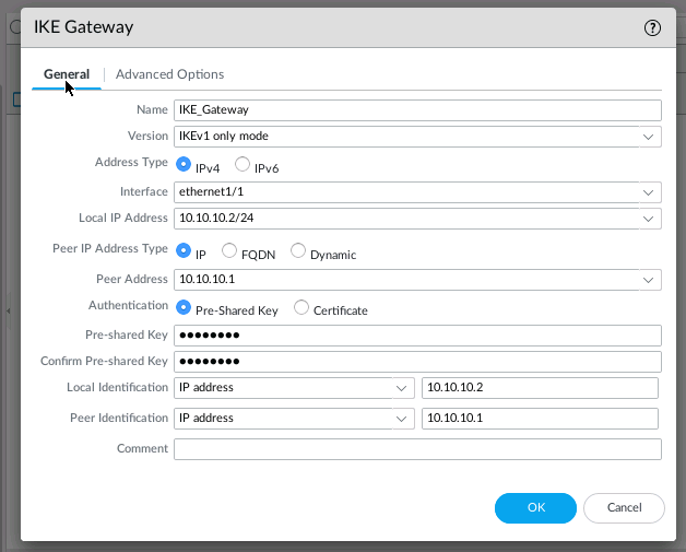
6. Create an IKE Gateway with following information:
Name: IKE_Gateway
interface: ethernet 1/1
Local IP Address: 10.10.10.2/24
Peer Address: 10.10.10.1
Pre-SharedKey: cisco123
Advanced Options> Exchange mode: main
Advanced Options> IKE Crypto Profile: IKEProfile
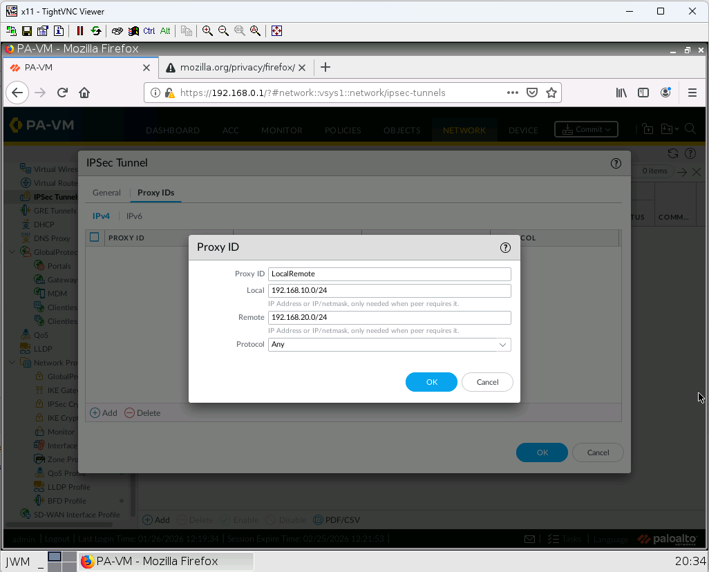
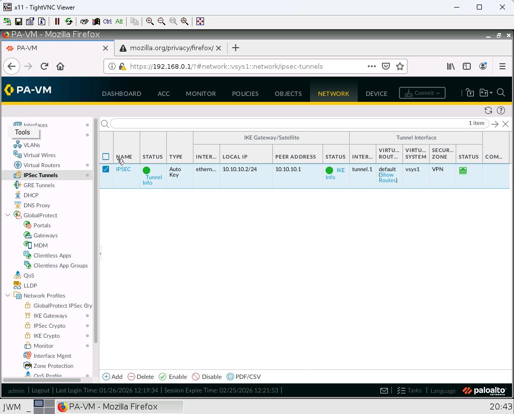
7. Create an IPSEC tunnel with following information:
Name: IPSEC
Tunnel Interface: tunnel1
IKE Gateway: IKE_Gateway
IPSEC Crypto Profile: IPSECProfile
Proxy ID: ProxyID: LocalRemote Local: 192.168.10.0/24 Remote: 192.168.20.0/24
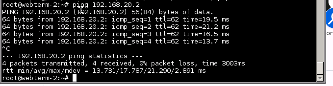
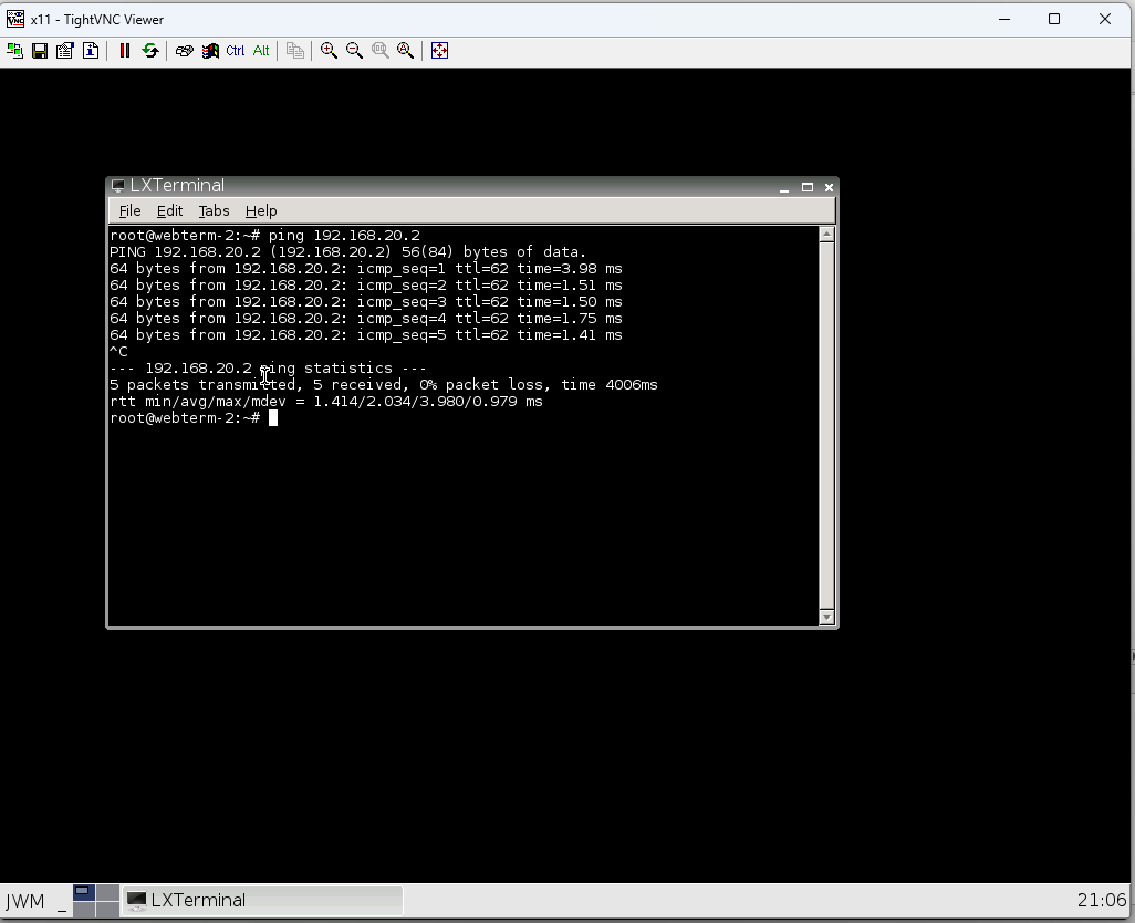
8. Successful ping from 192.168.10.2 to 192.168.20.2
9. Check status of your tunnel.
FortiGate
- Now, add the FortiGate device in the following diagram.
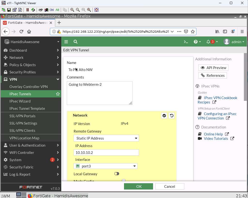
2. Configure a custom VPN Tunnel with following information:
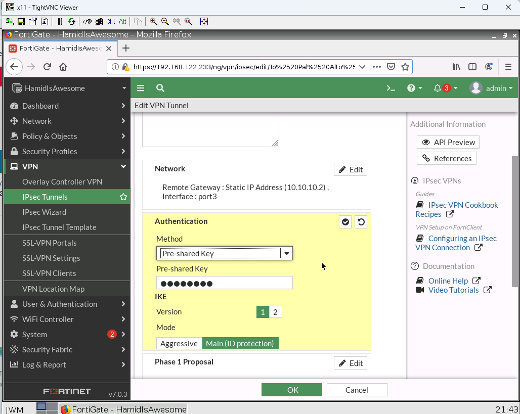
- Remote Gateway
IP Address: 10.10.10.2
Interface: Port 3
- Authentication
Method: Pre-shared Key
Pre-shared Key: cisco123
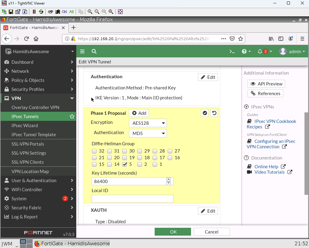
- Phase 1 Proposal
Encryption: AES128 Authentication: MD5 Group: 5
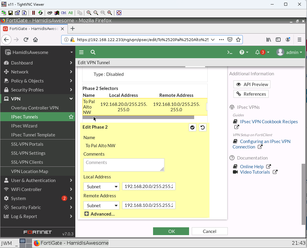
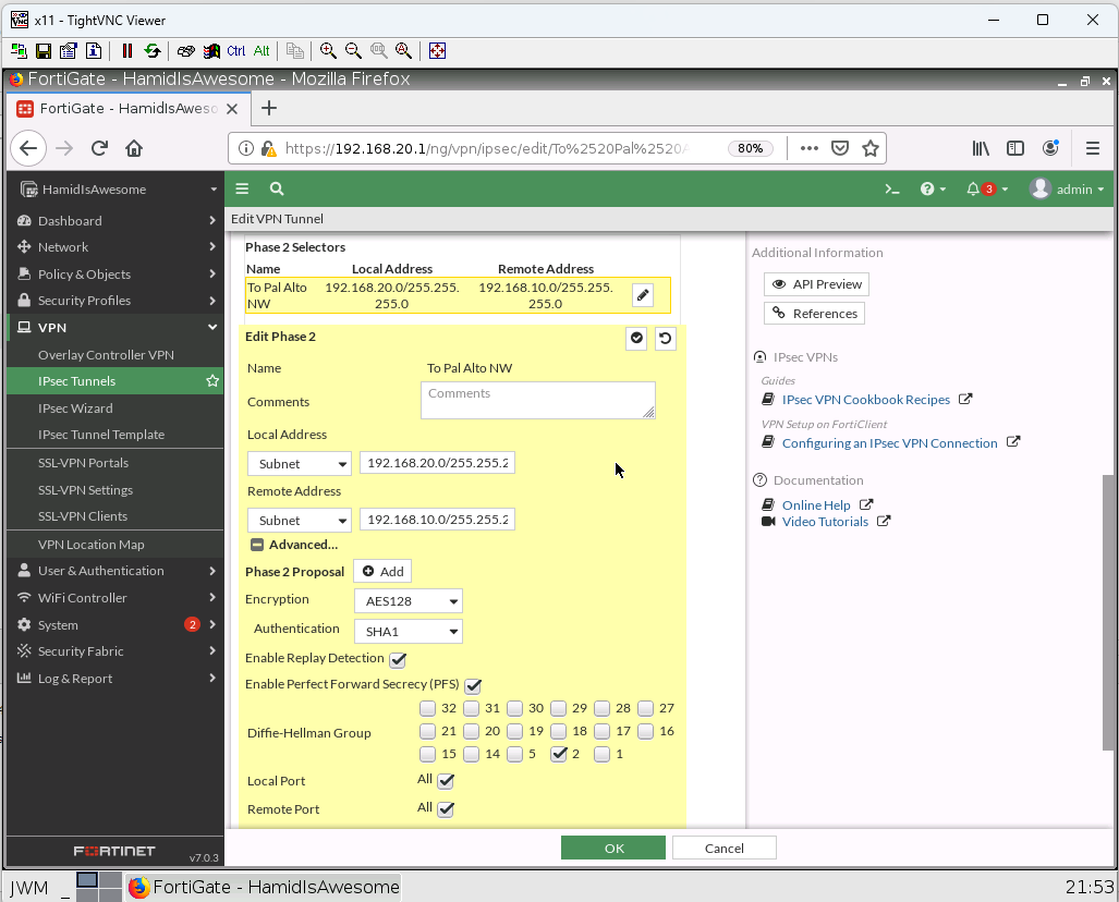
- Phase 2 Selectors
Local Address: 192.168.20.0/24 Remote Address: 192.168.10.0/24
Advanced: Encryption: AES128 Authentication: SHA1 Group: 2
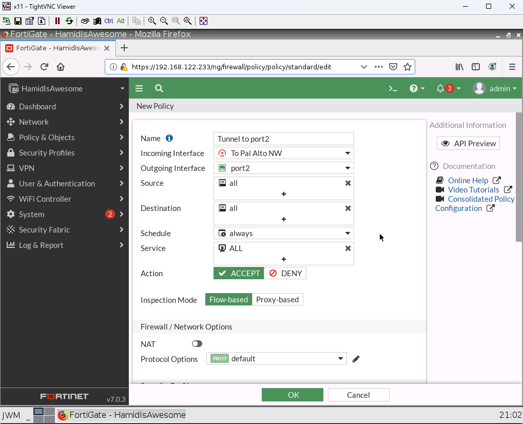
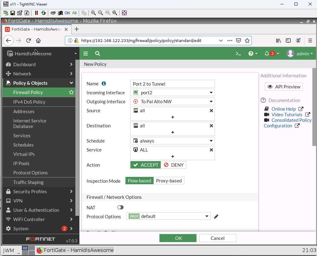
3. Create a Security IPV4 Policy from Tunnel to Port2 and from Port2 to Tunnel and allow all traffic (NAT should be disabled)
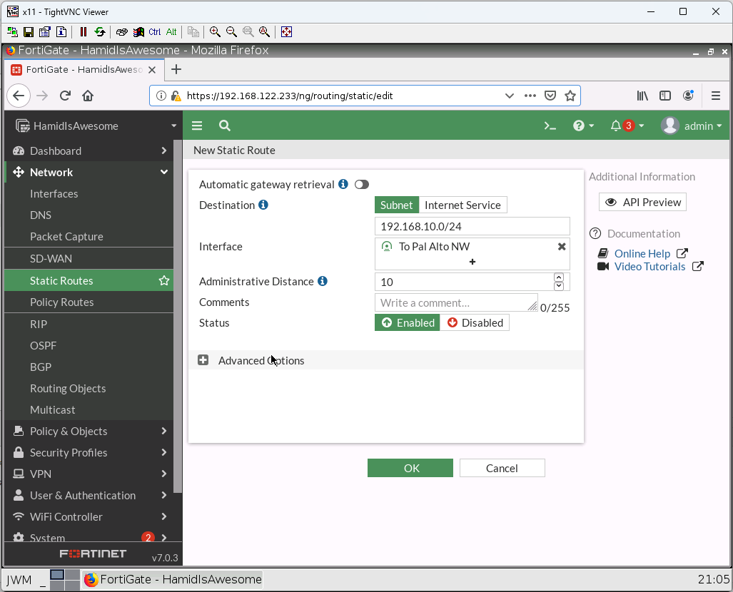
4. Create a static route with following information:
Destination: 192.168.10.0/24
Interface: Tunnel
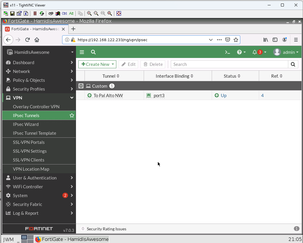
5. Verify your configuration ( FortiGate and Palo Alto)
6. You should be able to ping from WebTerm2 to WebTerm3.
Document is generated by Michael Sue
