Chapter 19 Electric Potential and Electric Field
150 19.6 Capacitors in Series and Parallel
Summary
- Derive expressions for total capacitance in series and in parallel.
- Identify series and parallel parts in the combination of connection of capacitors.
- Calculate the effective capacitance in series and parallel given individual capacitances.
Several capacitors may be connected together in a variety of applications. Multiple connections of capacitors act like a single equivalent capacitor. The total capacitance of this equivalent single capacitor depends both on the individual capacitors and how they are connected. There are two simple and common types of connections, called series and parallel, for which we can easily calculate the total capacitance. Certain more complicated connections can also be related to combinations of series and parallel.
Capacitance in Series
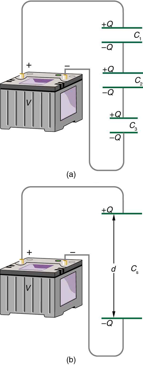
Figure 1(a) shows a series connection of three capacitors with a voltage applied. As for any capacitor, the capacitance of the combination is related to charge and voltage by [latex]\boldsymbol{C = \frac{Q}{V}}[/latex].
Note in Figure 1 that opposite charges of magnitude [latex]\boldsymbol{Q}[/latex] flow to either side of the originally uncharged combination of capacitors when the voltage [latex]\boldsymbol{V}[/latex] is applied. Conservation of charge requires that equal-magnitude charges be created on the plates of the individual capacitors, since charge is only being separated in these originally neutral devices. The end result is that the combination resembles a single capacitor with an effective plate separation greater than that of the individual capacitors alone. (See Figure 1(b).) Larger plate separation means smaller capacitance. It is a general feature of series connections of capacitors that the total capacitance is less than any of the individual capacitances.
We can find an expression for the total capacitance by considering the voltage across the individual capacitors shown in Figure 1. Solving [latex]\boldsymbol{C = \frac{Q}{V}}[/latex] for [latex]\boldsymbol{V}[/latex] gives [latex]\boldsymbol{V = \frac{Q}{C}}[/latex]. The voltages across the individual capacitors are thus [latex]\boldsymbol{V_1 = \frac{Q}{C_1}}[/latex], [latex]\boldsymbol{V_2 = \frac{Q}{C_2}}[/latex], and [latex]\boldsymbol{V_3 = \frac{Q}{C_3}}[/latex]. The total voltage is the sum of the individual voltages:
Now, calling the total capacitance [latex]\boldsymbol{C_S}[/latex] for series capacitance, consider that
Entering the expressions for [latex]\boldsymbol{V_1}[/latex], [latex]\boldsymbol{V_2}[/latex], and [latex]\boldsymbol{V_3}[/latex], we get
Canceling the [latex]\boldsymbol{Q}[/latex]s, we obtain the equation for the total capacitance in series [latex]\boldsymbol{C_S}[/latex] to be
where “...” indicates that the expression is valid for any number of capacitors connected in series. An expression of this form always results in a total capacitance [latex]\boldsymbol{C_S}[/latex] that is less than any of the individual capacitances [latex]\boldsymbol{C_1}[/latex], [latex]\boldsymbol{C_2}[/latex], ..., as the next example illustrates.
Total Capacitance in Series, Cs
Total capacitance in series: [latex]\boldsymbol{\frac{1}{C_S} = \frac{1}{C_1} + \frac{1}{C_2} + \frac{1}{C_3} + \cdots}[/latex]
Example 1: What Is the Series Capacitance?
Find the total capacitance for three capacitors connected in series, given their individual capacitances are 1.000, 5.000, and 8.000 [latex]\mu \textbf{F}[/latex].
Strategy
With the given information, the total capacitance can be found using the equation for capacitance in series.
Solution
Entering the given capacitances into the expression for [latex]\boldsymbol{\frac{1}{C_S}}[/latex] gives [latex]\boldsymbol{\frac{1}{C_S} = \frac{1}{C_1} + \frac{1}{C_2} + \frac{1}{C_3}}[/latex].
Inverting to find [latex]\boldsymbol{C_S}[/latex] yields [latex]\boldsymbol{C_S = \frac{\mu \textbf{F}}{1.325} = 0.755 \;\mu \textbf{F}}[/latex].
Discussion
The total series capacitance [latex]\boldsymbol{C_s}[/latex] is less than the smallest individual capacitance, as promised. In series connections of capacitors, the sum is less than the parts. In fact, it is less than any individual. Note that it is sometimes possible, and more convenient, to solve an equation like the above by finding the least common denominator, which in this case (showing only whole-number calculations) is 40. Thus,
so that
Capacitors in Parallel
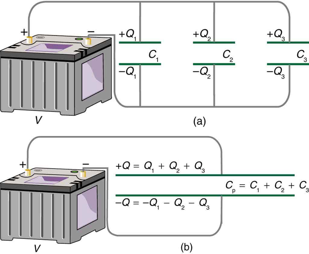
Figure 2(a) shows a parallel connection of three capacitors with a voltage applied. Here the total capacitance is easier to find than in the series case. To find the equivalent total capacitance [latex]\boldsymbol{\textbf{C}_{\textbf{p}}}[/latex], we first note that the voltage across each capacitor is [latex]\boldsymbol{V}[/latex], the same as that of the source, since they are connected directly to it through a conductor. (Conductors are equipotentials, and so the voltage across the capacitors is the same as that across the voltage source.) Thus the capacitors have the same charges on them as they would have if connected individually to the voltage source. The total charge [latex]\boldsymbol{Q}[/latex] is the sum of the individual charges:
Using the relationship [latex]\boldsymbol{Q = CV}[/latex], we see that the total charge is [latex]\boldsymbol{Q = C_{\textbf{p}}V}[/latex], and the individual charges are [latex]\boldsymbol{Q_1 = C_1 V}[/latex], [latex]\boldsymbol{Q_2 = C_2 V}[/latex], and [latex]\boldsymbol{Q_3 = C_3 V}[/latex]. Entering these into the previous equation gives
Canceling [latex]\boldsymbol{V}[/latex] from the equation, we obtain the equation for the total capacitance in parallel [latex]\boldsymbol{C_{\textbf{p}}}[/latex]:
Total capacitance in parallel is simply the sum of the individual capacitances. (Again the “...” indicates the expression is valid for any number of capacitors connected in parallel.) So, for example, if the capacitors in the example above were connected in parallel, their capacitance would be
The equivalent capacitor for a parallel connection has an effectively larger plate area and, thus, a larger capacitance, as illustrated in Figure 2(b).
Total Capacitance in Parallel, Cp [latex]\boldsymbol{C_{\textbf{p}}}[/latex]
Total capacitance in parallel [latex]\boldsymbol{C_{\textbf{p}} = C_1 + C_2 + C_3 + \cdots}[/latex]
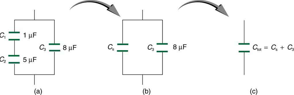
More complicated connections of capacitors can sometimes be combinations of series and parallel. (See Figure 3.) To find the total capacitance of such combinations, we identify series and parallel parts, compute their capacitances, and then find the total.
A Mixture of Series and Parallel Capacitance
Find the total capacitance of the combination of capacitors shown in Figure 3. Assume the capacitances in Figure 3 are known to three decimal places ([latex]\boldsymbol{C_1 = 1.000 \;\mu\textbf{F}}[/latex], [latex]\boldsymbol{C_2 = 5.000 \;\mu \textbf{F}}[/latex], and [latex]\boldsymbol{C_3 = 8.000 \;\mu \textbf{F}}[/latex]), and round your answer to three decimal places.
Strategy
To find the total capacitance, we first identify which capacitors are in series and which are in parallel. Capacitors [latex]\boldsymbol{C_1}[/latex] and [latex]\boldsymbol{C_2}[/latex] are in series. Their combination, labeled [latex]\boldsymbol{C_S}[/latex] in the figure, is in parallel with [latex]\boldsymbol{C_3}[/latex].
Solution
Since [latex]\boldsymbol{C_1}[/latex] and [latex]\boldsymbol{C_2}[/latex] are in series, their total capacitance is given by [latex]\boldsymbol{\frac{1}{C_S} = \frac{1}{C_1} + \frac{1}{C_2} + \frac{1}{C_3}}[/latex]. Entering their values into the equation gives
Inverting gives
This equivalent series capacitance is in parallel with the third capacitor; thus, the total is the sum
Discussion
This technique of analyzing the combinations of capacitors piece by piece until a total is obtained can be applied to larger combinations of capacitors.
Section Summary
- Total capacitance in series [latex]\boldsymbol{\frac{1}{C_{\textbf{S}}} = \frac{1}{C_1} + \frac{1}{C_2} + \frac{1}{C_3} + \cdots }[/latex]
- Total capacitance in parallel [latex]\boldsymbol{C_{\textbf{p}} = C_1 + C_2 + C_3 + \cdots }[/latex]
- If a circuit contains a combination of capacitors in series and parallel, identify series and parallel parts, compute their capacitances, and then find the total.
Conceptual Questions
1: If you wish to store a large amount of energy in a capacitor bank, would you connect capacitors in series or parallel? Explain.
Problems & Exercises
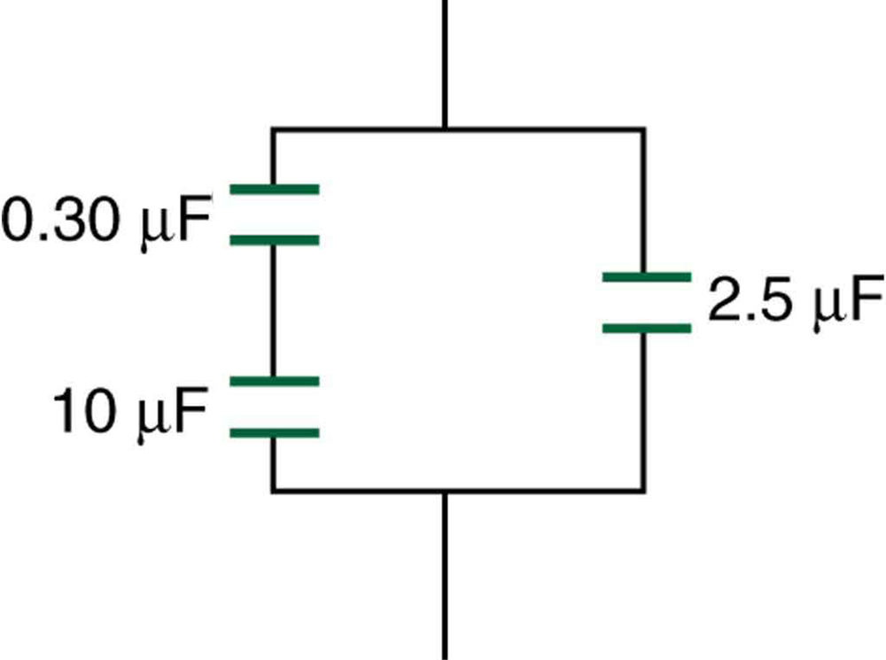
1: Find the total capacitance of the combination of capacitors in Figure 4.
2: Suppose you want a capacitor bank with a total capacitance of 0.750 F and you possess numerous 1.50 mF capacitors. What is the smallest number you could hook together to achieve your goal, and how would you connect them?
3: What total capacitances can you make by connecting a [latex]\boldsymbol{5.00 \;\mu \textbf{F}}[/latex] and an [latex]\boldsymbol{8.00 \;\mu\textbf{F}}[/latex] capacitor together?
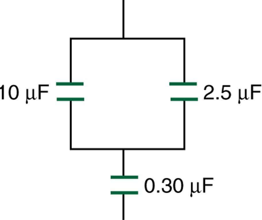
4: Find the total capacitance of the combination of capacitors shown in Figure 5.
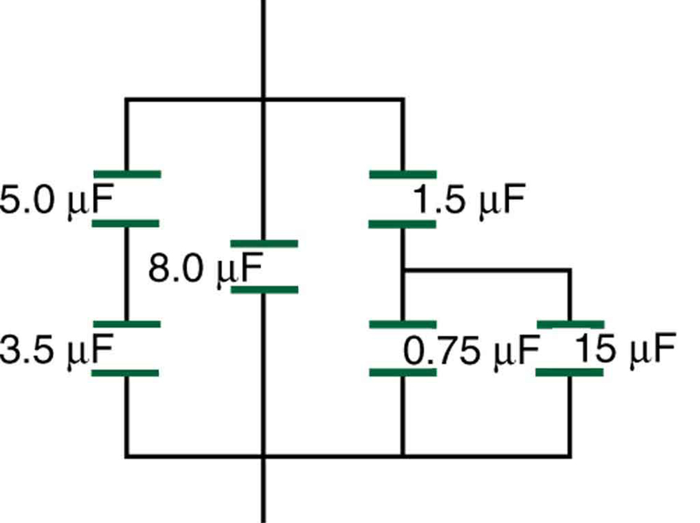
5: Find the total capacitance of the combination of capacitors shown in Figure 6.
6: Unreasonable Results
(a) An [latex]\boldsymbol{8.00 \;\mu \textbf{F}}[/latex] capacitor is connected in parallel to another capacitor, producing a total capacitance of [latex]\boldsymbol{5.00 \;\mu \textbf{F}}[/latex]. What is the capacitance of the second capacitor? (b) What is unreasonable about this result? (c) Which assumptions are unreasonable or inconsistent?
Solutions
Problems & Exercises
1: [latex]\boldsymbol{0.293 \;\mu \textbf{F}}[/latex]
3: [latex]\boldsymbol{3.08 \;\mu \textbf{F}}[/latex] in series combination, [latex]\boldsymbol{13.0 \;\mu \textbf{F}}[/latex] in parallel combination
4: [latex]\boldsymbol{2.79 \;\mu \textbf{F}}[/latex]
6: (a) [latex]\boldsymbol{-3.00 \;\mu \textbf{F}}[/latex]
(b) You cannot have a negative value of capacitance.
(c) The assumption that the capacitors were hooked up in parallel, rather than in series, was incorrect. A parallel connection always produces a greater capacitance, while here a smaller capacitance was assumed. This could happen only if the capacitors are connected in series.
