Chapter 26 Vision and Optical Instruments
210 26.5 Telescopes
Summary
- Outline the invention of a telescope.
- Describe the working of a telescope.
Telescopes are meant for viewing distant objects, producing an image that is larger than the image that can be seen with the unaided eye. Telescopes gather far more light than the eye, allowing dim objects to be observed with greater magnification and better resolution. Although Galileo is often credited with inventing the telescope, he actually did not. What he did was more important. He constructed several early telescopes, was the first to study the heavens with them, and made monumental discoveries using them. Among these are the moons of Jupiter, the craters and mountains on the Moon, the details of sunspots, and the fact that the Milky Way is composed of vast numbers of individual stars.
Figure 1(a) shows a telescope made of two lenses, the convex objective and the concave eyepiece, the same construction used by Galileo. Such an arrangement produces an upright image and is used in spyglasses and opera glasses.
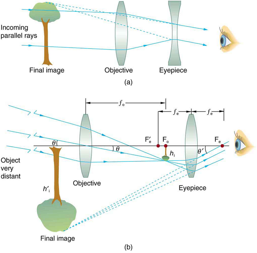
The most common two-lens telescope, like the simple microscope, uses two convex lenses and is shown in Figure 1(b). The object is so far away from the telescope that it is essentially at infinity compared with the focal lengths of the lenses ([latex]\boldsymbol{d_{\textbf{o}} \approx \infty}[/latex]). The first image is thus produced at [latex]\boldsymbol{d_{\textbf{i}} = f_{\textbf{o}}}[/latex], as shown in the figure. To prove this, note that
Because [latex]\boldsymbol{1/ \infty =0}[/latex], this simplifies to
which implies that [latex]\boldsymbol{d_{\textbf{i}} = f_{\textbf{o}}}[/latex], as claimed. It is true that for any distant object and any lens or mirror, the image is at the focal length.
The first image formed by a telescope objective as seen in Figure 1(b) will not be large compared with what you might see by looking at the object directly. For example, the spot formed by sunlight focused on a piece of paper by a magnifying glass is the image of the Sun, and it is small. The telescope eyepiece (like the microscope eyepiece) magnifies this first image. The distance between the eyepiece and the objective lens is made slightly less than the sum of their focal lengths so that the first image is closer to the eyepiece than its focal length. That is, [latex]\boldsymbol{{d_{\textbf{o}}}^{\prime}}[/latex] is less than [latex]\boldsymbol{f_{\textbf{e}}}[/latex], and so the eyepiece forms a case 2 image that is large and to the left for easy viewing. If the angle subtended by an object as viewed by the unaided eye is [latex]\boldsymbol{\theta}[/latex], and the angle subtended by the telescope image is [latex]\boldsymbol{\theta ^{\prime}}[/latex], then the angular magnification [latex]\boldsymbol{M}[/latex] is defined to be their ratio. That is, [latex]\boldsymbol{M= \theta ^{\prime}}[/latex]. It can be shown that the angular magnification of a telescope is related to the focal lengths of the objective and eyepiece; and is given by
The minus sign indicates the image is inverted. To obtain the greatest angular magnification, it is best to have a long focal length objective and a short focal length eyepiece. The greater the angular magnification [latex]\boldsymbol{M}[/latex], the larger an object will appear when viewed through a telescope, making more details visible. Limits to observable details are imposed by many factors, including lens quality and atmospheric disturbance.
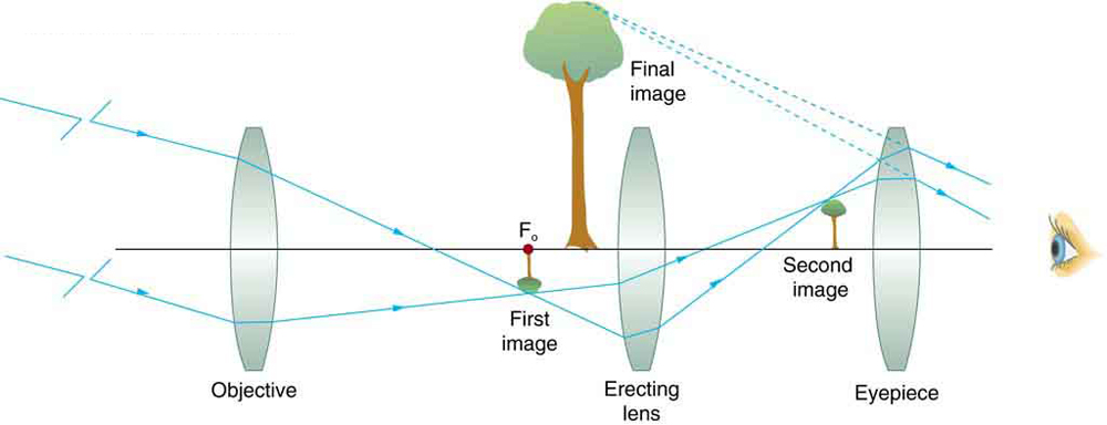
The image in most telescopes is inverted, which is unimportant for observing the stars but a real problem for other applications, such as telescopes on ships or telescopic gun sights. If an upright image is needed, Galileo’s arrangement in Figure 1(a) can be used. But a more common arrangement is to use a third convex lens as an eyepiece, increasing the distance between the first two and inverting the image once again as seen in Figure 2.
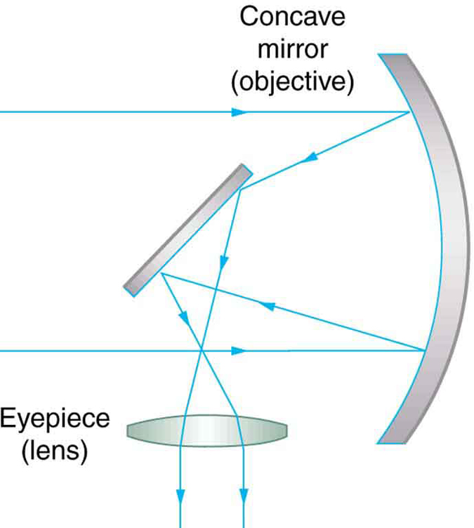
A telescope can also be made with a concave mirror as its first element or objective, since a concave mirror acts like a convex lens as seen in Figure 3. Flat mirrors are often employed in optical instruments to make them more compact or to send light to cameras and other sensing devices. There are many advantages to using mirrors rather than lenses for telescope objectives. Mirrors can be constructed much larger than lenses and can, thus, gather large amounts of light, as needed to view distant galaxies, for example. Large and relatively flat mirrors have very long focal lengths, so that great angular magnification is possible.
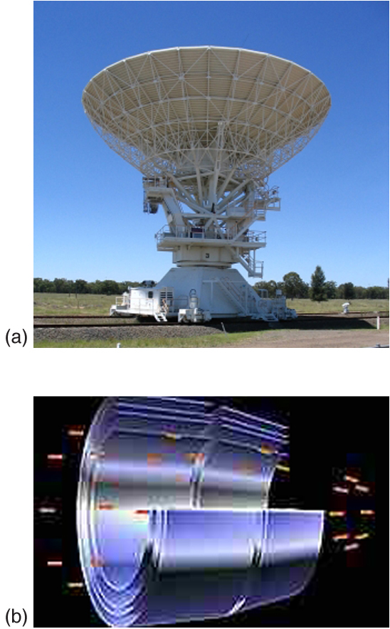
Telescopes, like microscopes, can utilize a range of frequencies from the electromagnetic spectrum. Figure 4(a) shows the Australia Telescope Compact Array, which uses six 22-m antennas for mapping the southern skies using radio waves. Figure 4(b) shows the focusing of x rays on the Chandra X-ray Observatory—a satellite orbiting earth since 1999 and looking at high temperature events as exploding stars, quasars, and black holes. X rays, with much more energy and shorter wavelengths than RF and light, are mainly absorbed and not reflected when incident perpendicular to the medium. But they can be reflected when incident at small glancing angles, much like a rock will skip on a lake if thrown at a small angle. The mirrors for the Chandra consist of a long barrelled pathway and 4 pairs of mirrors to focus the rays at a point 10 meters away from the entrance. The mirrors are extremely smooth and consist of a glass ceramic base with a thin coating of metal (iridium). Four pairs of precision manufactured mirrors are exquisitely shaped and aligned so that x rays ricochet off the mirrors like bullets off a wall, focusing on a spot.
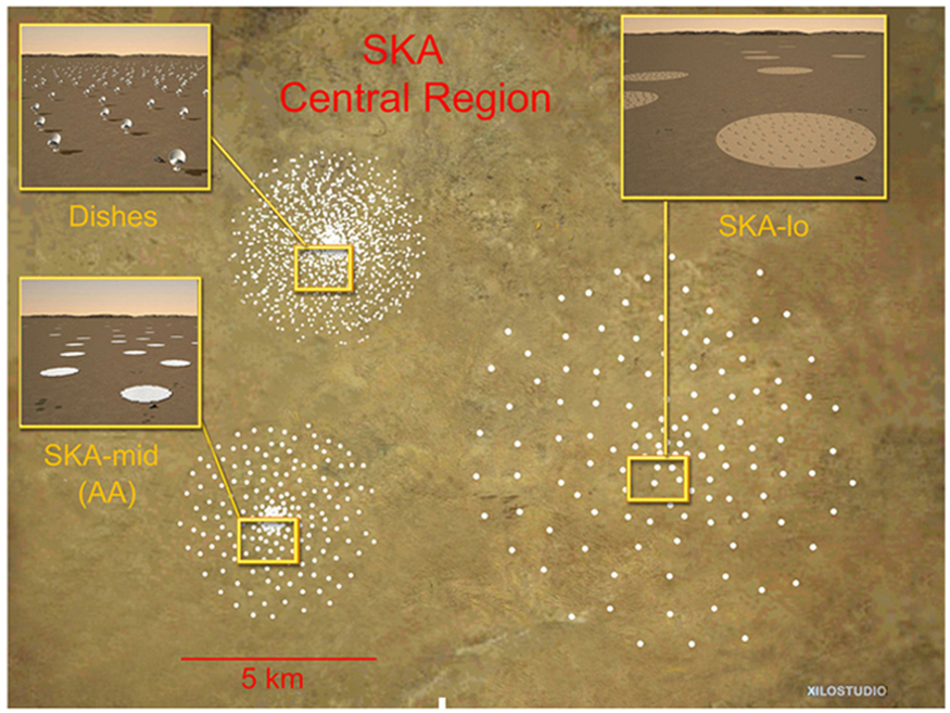
A current exciting development is a collaborative effort involving 17 countries to construct a Square Kilometre Array (SKA) of telescopes capable of covering from 80 MHz to 2 GHz. The initial stage of the project is the construction of the Australian Square Kilometre Array Pathfinder in Western Australia (see Figure 5). The project will use cutting-edge technologies such as adaptive optics in which the lens or mirror is constructed from lots of carefully aligned tiny lenses and mirrors that can be manipulated using computers. A range of rapidly changing distortions can be minimized by deforming or tilting the tiny lenses and mirrors. The use of adaptive optics in vision correction is a current area of research.
Section Summary
- Simple telescopes can be made with two lenses. They are used for viewing objects at large distances and utilize the entire range of the electromagnetic spectrum.
- The angular magnification M for a telescope is given by
[latex]\boldsymbol{M =}[/latex][latex]\boldsymbol{\frac{\theta ^{\prime}}{\theta}}[/latex][latex]\boldsymbol{=-}[/latex][latex]\boldsymbol{\frac{f_{\textbf{o}}}{f_{\textbf{e}}}},[/latex]
where [latex]\boldsymbol{\theta}[/latex] is the angle subtended by an object viewed by the unaided eye, [latex]\boldsymbol{\theta ^{\prime}}[/latex] is the angle subtended by a magnified image, and [latex]\boldsymbol{f_{\textbf{o}}}[/latex] and [latex]\boldsymbol{f_{\textbf{e}}}[/latex] are the focal lengths of the objective and the eyepiece.
Conceptual Questions
1: If you want your microscope or telescope to project a real image onto a screen, how would you change the placement of the eyepiece relative to the objective?
Problem Exercises
Unless otherwise stated, the lens-to-retina distance is 2.00 cm.
1: What is the angular magnification of a telescope that has a 100 cm focal length objective and a 2.50 cm focal length eyepiece?
2: Find the distance between the objective and eyepiece lenses in the telescope in the above problem needed to produce a final image very far from the observer, where vision is most relaxed. Note that a telescope is normally used to view very distant objects.
3: A large reflecting telescope has an objective mirror with a [latex]\boldsymbol{10.0 \;\textbf{m}}[/latex] radius of curvature. What angular magnification does it produce when a [latex]\boldsymbol{3.00 \;\textbf{m}}[/latex] focal length eyepiece is used?
4: A small telescope has a concave mirror with a 2.00 m radius of curvature for its objective. Its eyepiece is a 4.00 cm focal length lens. (a) What is the telescope’s angular magnification? (b) What angle is subtended by a 25,000 km diameter sunspot? (c) What is the angle of its telescopic image?
5: A [latex]\boldsymbol{7.5 \times}[/latex] binocular produces an angular magnification of [latex]\boldsymbol{-7.50}[/latex], acting like a telescope. (Mirrors are used to make the image upright.) If the binoculars have objective lenses with a 75.0 cm focal length, what is the focal length of the eyepiece lenses?
6: Construct Your Own Problem
Consider a telescope of the type used by Galileo, having a convex objective and a concave eyepiece as illustrated in Figure 1(a). Construct a problem in which you calculate the location and size of the image produced. Among the things to be considered are the focal lengths of the lenses and their relative placements as well as the size and location of the object. Verify that the angular magnification is greater than one. That is, the angle subtended at the eye by the image is greater than the angle subtended by the object.
Glossary
- adaptive optics
- optical technology in which computers adjust the lenses and mirrors in a device to correct for image distortions
- angular magnification
- a ratio related to the focal lengths of the objective and eyepiece and given as [latex]\boldsymbol{M = -\frac{f_{\textbf{o}}}{f_{\textbf{e}}}}[/latex]
Solutions
Problem Exercises
1: [latex]\boldsymbol{- 40.0}[/latex]
3: [latex]\boldsymbol{-1.67}[/latex]
5: [latex]\boldsymbol{+10.0 \;\textbf{cm}}[/latex]
