Chapter 15 Thermodynamics
109 15.2 The First Law of Thermodynamics and Some Simple Processes
Summary
- Describe the processes of a simple heat engine.
- Explain the differences among the simple thermodynamic processes—isobaric, isochoric, isothermal, and adiabatic.
- Calculate total work done in a cyclical thermodynamic process.
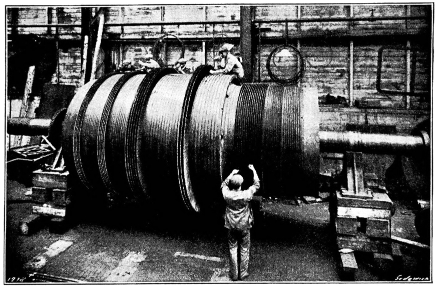
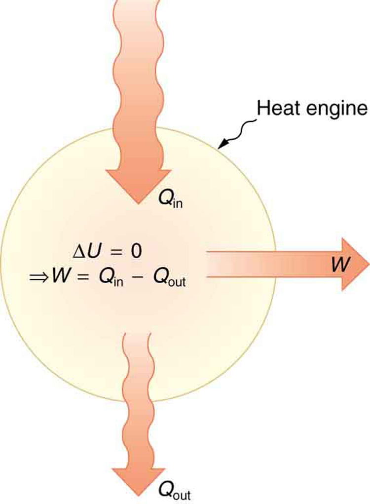
One of the most important things we can do with heat transfer is to use it to do work for us. Such a device is called a heat engine. Car engines and steam turbines that generate electricity are examples of heat engines. Figure 2 shows schematically how the first law of thermodynamics applies to the typical heat engine.
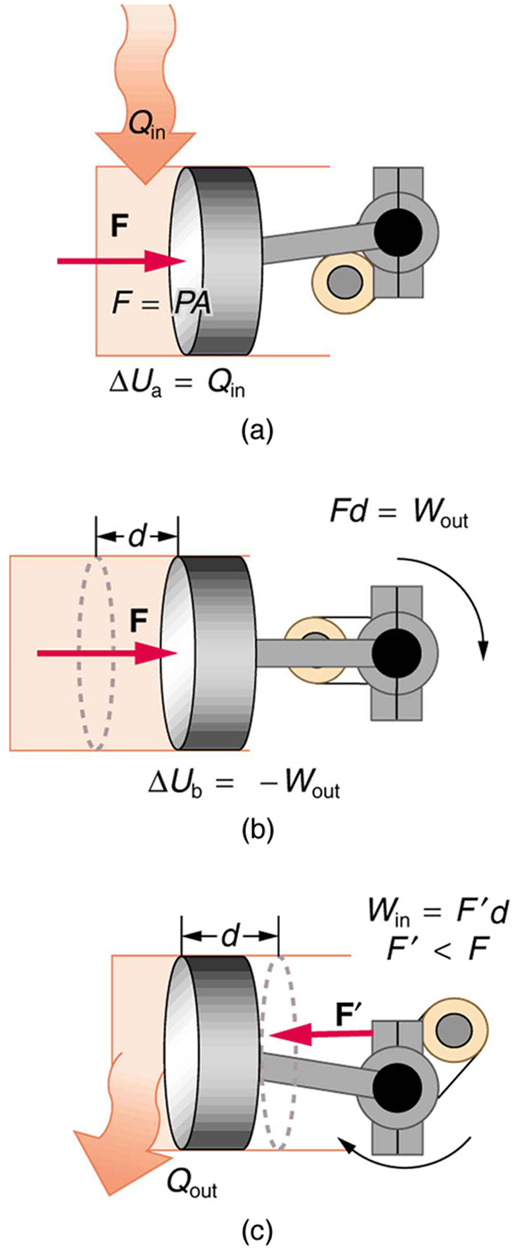
The illustrations above show one of the ways in which heat transfer does work. Fuel combustion produces heat transfer to a gas in a cylinder, increasing the pressure of the gas and thereby the force it exerts on a movable piston. The gas does work on the outside world, as this force moves the piston through some distance. Heat transfer to the gas cylinder results in work being done. To repeat this process, the piston needs to be returned to its starting point. Heat transfer now occurs from the gas to the surroundings so that its pressure decreases, and a force is exerted by the surroundings to push the piston back through some distance. Variations of this process are employed daily in hundreds of millions of heat engines. We will examine heat engines in detail in the next section. In this section, we consider some of the simpler underlying processes on which heat engines are based.
PV Diagrams and their Relationship to Work Done on or by a Gas
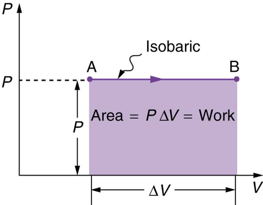
A process by which a gas does work on a piston at constant pressure is called an isobaric process. Since the pressure is constant, the force exerted is constant and the work done is given as
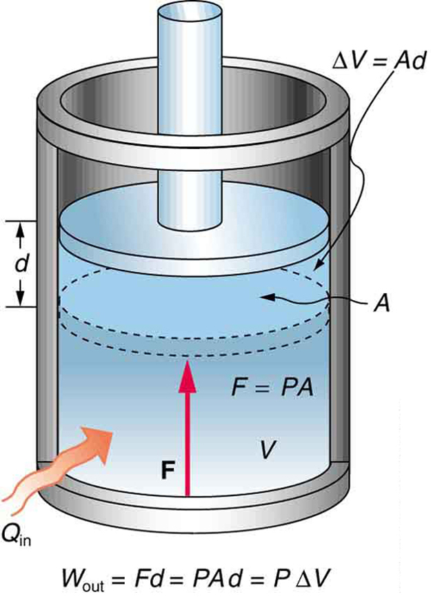
See the symbols as shown in Figure 4. Now[latex]\boldsymbol{F=PA},[/latex]and so
Because the volume of a cylinder is its cross-sectional area[latex]\boldsymbol{A}[/latex]times its length[latex]\boldsymbol{d},[/latex]we see that[latex]\boldsymbol{Ad=\Delta{V}},[/latex]the change in volume; thus,
Note that if[latex]\boldsymbol{\Delta{V}}[/latex]is positive, then[latex]\boldsymbol{W}[/latex]is positive, meaning that work is done by the gas on the outside world.
(Note that the pressure involved in this work that we’ve called[latex]\boldsymbol{P}[/latex]is the pressure of the gas inside the tank. If we call the pressure outside the tank[latex]\boldsymbol{P_{\textbf{ext}}},[/latex]an expanding gas would be working against the external pressure; the work done would therefore be[latex]\boldsymbol{W=-P_{\textbf{ext}}\Delta{V}}[/latex](isobaric process). Many texts use this definition of work, and not the definition based on internal pressure, as the basis of the First Law of Thermodynamics. This definition reverses the sign conventions for work, and results in a statement of the first law that becomes[latex]\boldsymbol{\Delta{U}=Q+W}[/latex].)
It is not surprising that[latex]\boldsymbol{W=P\Delta{V}},[/latex]since we have already noted in our treatment of fluids that pressure is a type of potential energy per unit volume and that pressure in fact has units of energy divided by volume. We also noted in our discussion of the ideal gas law that[latex]\boldsymbol{PV}[/latex]has units of energy. In this case, some of the energy associated with pressure becomes work.
Figure 5 shows a graph of pressure versus volume (that is, a[latex]\boldsymbol{PV}[/latex]diagram for an isobaric process. You can see in the figure that the work done is the area under the graph. This property of[latex]\boldsymbol{PV}[/latex]diagrams is very useful and broadly applicable: the work done on or by a system in going from one state to another equals the area under the curve on a[latex]\boldsymbol{PV}[/latex]diagram.
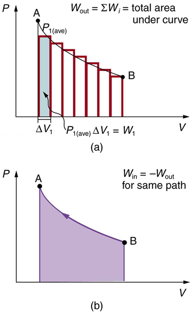
We can see where this leads by considering Figure 6(a), which shows a more general process in which both pressure and volume change. The area under the curve is closely approximated by dividing it into strips, each having an average constant pressure[latex]\boldsymbol{P_{\textbf{i(ave)}}}.[/latex]The work done is[latex]\boldsymbol{W_{\textbf{i}}=P_{\textbf{i(ave)}}\Delta{V}_{\textbf{i}}}[/latex]for each strip, and the total work done is the sum of the[latex]\boldsymbol{W_{\textbf{i}}}.[/latex]Thus the total work done is the total area under the curve. If the path is reversed, as in Figure 6(b), then work is done on the system. The area under the curve in that case is negative, because[latex]\boldsymbol{\Delta{V}}[/latex]is negative.
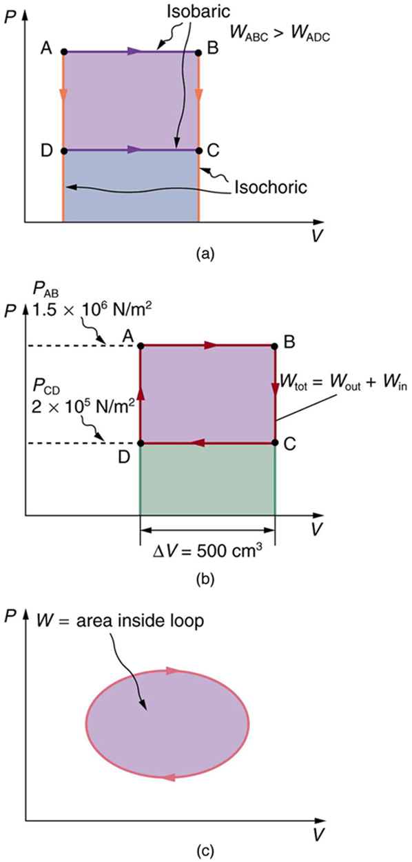
[latex]\boldsymbol{PV}[/latex]diagrams clearly illustrate that the work done depends on the path taken and not just the endpoints. This path dependence is seen in Figure 7(a), where more work is done in going from A to C by the path via point B than by the path via point D. The vertical paths, where volume is constant, are called isochoric processes. Since volume is constant,[latex]\boldsymbol{\Delta{V}=0},[/latex]and no work is done in an isochoric process. Now, if the system follows the cyclical path ABCDA, as in Figure 7(b), then the total work done is the area inside the loop. The negative area below path CD subtracts, leaving only the area inside the rectangle. In fact, the work done in any cyclical process (one that returns to its starting point) is the area inside the loop it forms on a[latex]\boldsymbol{PV}[/latex]diagram, as Figure 7(c) illustrates for a general cyclical process. Note that the loop must be traversed in the clockwise direction for work to be positive—that is, for there to be a net work output.
Example 1: Total Work Done in a Cyclical Process Equals the Area Inside the Closed Loop on a Diagram
Calculate the total work done in the cyclical process ABCDA shown in Figure 7(b) by the following two methods to verify that work equals the area inside the closed loop on the[latex]\boldsymbol{PV}[/latex]diagram. (Take the data in the figure to be precise to three significant figures.) (a) Calculate the work done along each segment of the path and add these values to get the total work. (b) Calculate the area inside the rectangle ABCDA.
Strategy
To find the work along any path on a[latex]\boldsymbol{PV}[/latex]diagram, you use the fact that work is pressure times change in volume, or[latex]\boldsymbol{W=P\Delta{V}}.[/latex]So in part (a), this value is calculated for each leg of the path around the closed loop.
Solution for (a)
The work along path AB is
Since the path BC is isochoric,[latex]\boldsymbol{\Delta{V}_{\textbf{BC}}=0},[/latex]and so[latex]\boldsymbol{W_{\textbf{BC}}=0}.[/latex]The work along path CD is negative, since[latex]\boldsymbol{\Delta{V}_{\textbf{CD}}}[/latex]is negative (the volume decreases). The work is
Again, since the path DA is isochoric,[latex]\boldsymbol{\Delta{V}_{\textbf{DA}}=0},[/latex]and so[latex]\boldsymbol{W_{\textbf{DA}}=0}.[/latex]Now the total work is
Solution for (b)
The area inside the rectangle is its height times its width, or
Thus,
Discussion
The result, as anticipated, is that the area inside the closed loop equals the work done. The area is often easier to calculate than is the work done along each path. It is also convenient to visualize the area inside different curves on[latex]\boldsymbol{PV}[/latex]diagrams in order to see which processes might produce the most work. Recall that work can be done to the system, or by the system, depending on the sign of[latex]\boldsymbol{W}.[/latex]A positive[latex]\boldsymbol{W}[/latex]is work that is done by the system on the outside environment; a negative[latex]\boldsymbol{W}[/latex]represents work done by the environment on the system.
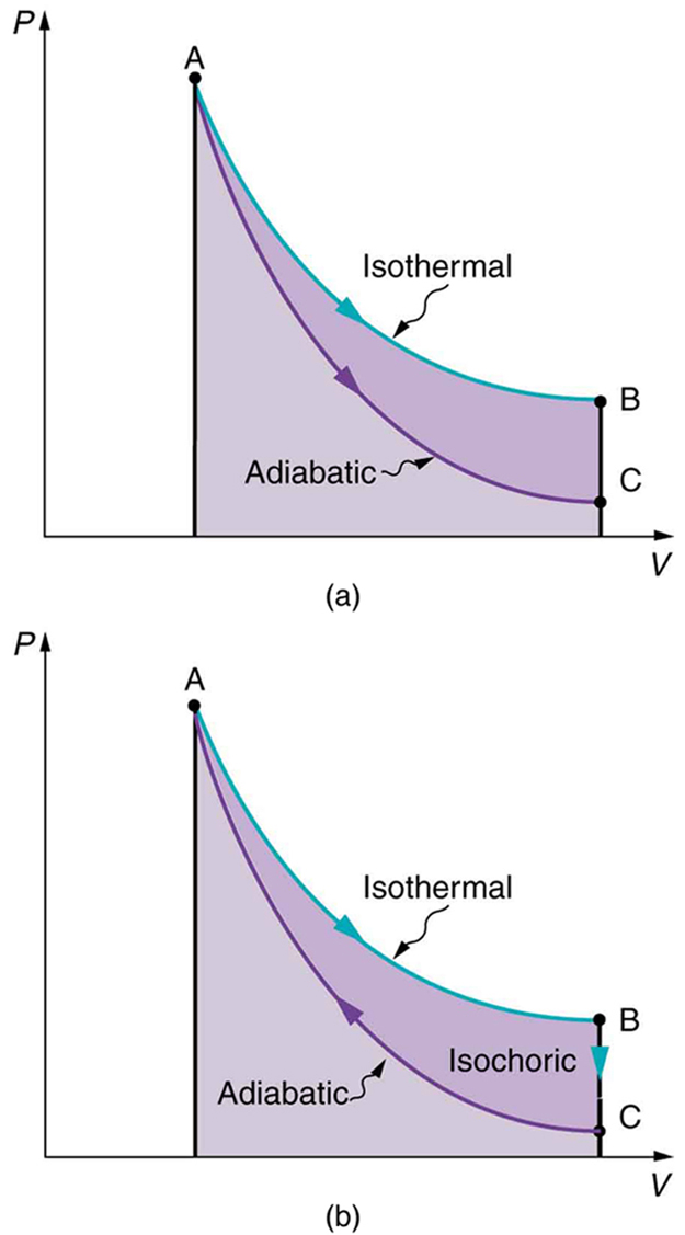
Figure 8(a) shows two other important processes on a[latex]\boldsymbol{PV}[/latex]diagram. For comparison, both are shown starting from the same point A. The upper curve ending at point B is an isothermal process—that is, one in which temperature is kept constant. If the gas behaves like an ideal gas, as is often the case, and if no phase change occurs, then[latex]\boldsymbol{PV=nRT}.[/latex]Since[latex]\boldsymbol{T}[/latex]is constant,[latex]\boldsymbol{PV}[/latex]is a constant for an isothermal process. We ordinarily expect the temperature of a gas to decrease as it expands, and so we correctly suspect that heat transfer must occur from the surroundings to the gas to keep the temperature constant during an isothermal expansion. To show this more rigorously for the special case of a monatomic ideal gas, we note that the average kinetic energy of an atom in such a gas is given by
The kinetic energy of the atoms in a monatomic ideal gas is its only form of internal energy, and so its total internal energy[latex]\boldsymbol{U}[/latex]is
where[latex]\boldsymbol{N}[/latex]is the number of atoms in the gas. This relationship means that the internal energy of an ideal monatomic gas is constant during an isothermal process—that is,[latex]\boldsymbol{\Delta{U}=0}.[/latex]If the internal energy does not change, then the net heat transfer into the gas must equal the net work done by the gas. That is, because[latex]\boldsymbol{\Delta{U}=Q-W=0}[/latex]here,[latex]\boldsymbol{Q=W}.[/latex]We must have just enough heat transfer to replace the work done. An isothermal process is inherently slow, because heat transfer occurs continuously to keep the gas temperature constant at all times and must be allowed to spread through the gas so that there are no hot or cold regions.
Also shown in Figure 8(a) is a curve AC for an adiabatic process, defined to be one in which there is no heat transfer—that is,[latex]\boldsymbol{Q=0}.[/latex]Processes that are nearly adiabatic can be achieved either by using very effective insulation or by performing the process so fast that there is little time for heat transfer. Temperature must decrease during an adiabatic process, since work is done at the expense of internal energy:
(You might have noted that a gas released into atmospheric pressure from a pressurized cylinder is substantially colder than the gas in the cylinder.) In fact, because[latex]\boldsymbol{Q=0,\:\Delta{U}=-W}[/latex]for an adiabatic process. Lower temperature results in lower pressure along the way, so that curve AC is lower than curve AB, and less work is done. If the path ABCA could be followed by cooling the gas from B to C at constant volume (isochorically), Figure 8(b), there would be a net work output.
Reversible Processes
Both isothermal and adiabatic processes such as shown in Figure 8 are reversible in principle. A reversible process is one in which both the system and its environment can return to exactly the states they were in by following the reverse path. The reverse isothermal and adiabatic paths are BA and CA, respectively. Real macroscopic processes are never exactly reversible. In the previous examples, our system is a gas (like that in Figure 4), and its environment is the piston, cylinder, and the rest of the universe. If there are any energy-dissipating mechanisms, such as friction or turbulence, then heat transfer to the environment occurs for either direction of the piston. So, for example, if the path BA is followed and there is friction, then the gas will be returned to its original state but the environment will not—it will have been heated in both directions. Reversibility requires the direction of heat transfer to reverse for the reverse path. Since dissipative mechanisms cannot be completely eliminated, real processes cannot be reversible.
There must be reasons that real macroscopic processes cannot be reversible. We can imagine them going in reverse. For example, heat transfer occurs spontaneously from hot to cold and never spontaneously the reverse. Yet it would not violate the first law of thermodynamics for this to happen. In fact, all spontaneous processes, such as bubbles bursting, never go in reverse. There is a second thermodynamic law that forbids them from going in reverse. When we study this law, we will learn something about nature and also find that such a law limits the efficiency of heat engines. We will find that heat engines with the greatest possible theoretical efficiency would have to use reversible processes, and even they cannot convert all heat transfer into doing work. Table 2 summarizes the simpler thermodynamic processes and their definitions.
| Isobaric | Constant pressure [latex]\boldsymbol{W=P\Delta{V}}[/latex] |
| Isochoric | Constant volume [latex]\boldsymbol{W=0}[/latex] |
| Isothermal | Constant temperature [latex]\boldsymbol{Q=W}[/latex] |
| Adiabatic | No heat transfer [latex]\boldsymbol{Q=0}[/latex] |
| Table 2. Summary of Simple Thermodynamic Processes | |
PHET EXPLORATIONS: STATES OF MATTER
Watch different types of molecules form a solid, liquid, or gas. Add or remove heat and watch the phase change. Change the temperature or volume of a container and see a pressure-temperature diagram respond in real time. Relate the interaction potential to the forces between molecules.
Section Summary
- One of the important implications of the first law of thermodynamics is that machines can be harnessed to do work that humans previously did by hand or by external energy supplies such as running water or the heat of the Sun. A machine that uses heat transfer to do work is known as a heat engine.
- There are several simple processes, used by heat engines, that flow from the first law of thermodynamics. Among them are the isobaric, isochoric, isothermal and adiabatic processes.
- These processes differ from one another based on how they affect pressure, volume, temperature, and heat transfer.
- If the work done is performed on the outside environment, work ([latex]\boldsymbol{W}[/latex]) will be a positive value. If the work done is done to the heat engine system, work ([latex]\boldsymbol{W}[/latex]) will be a negative value.
- Some thermodynamic processes, including isothermal and adiabatic processes, are reversible in theory; that is, both the thermodynamic system and the environment can be returned to their initial states. However, because of loss of energy owing to the second law of thermodynamics, complete reversibility does not work in practice.
Conceptual Questions
1: A great deal of effort, time, and money has been spent in the quest for the so-called perpetual-motion machine, which is defined as a hypothetical machine that operates or produces useful work indefinitely and/or a hypothetical machine that produces more work or energy than it consumes. Explain, in terms of heat engines and the first law of thermodynamics, why or why not such a machine is likely to be constructed.
2: One method of converting heat transfer into doing work is for heat transfer into a gas to take place, which expands, doing work on a piston, as shown in the figure below. (a) Is the heat transfer converted directly to work in an isobaric process, or does it go through another form first? Explain your answer. (b) What about in an isothermal process? (c) What about in an adiabatic process (where heat transfer occurred prior to the adiabatic process)?

3: Would the previous question make any sense for an isochoric process? Explain your answer.
4: We ordinarily say that[latex]\boldsymbol{\Delta{U}=0}[/latex]for an isothermal process. Does this assume no phase change takes place? Explain your answer.
5: The temperature of a rapidly expanding gas decreases. Explain why in terms of the first law of thermodynamics. (Hint: Consider whether the gas does work and whether heat transfer occurs rapidly into the gas through conduction.)
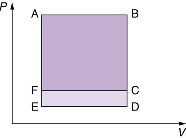
6: Which cyclical process represented by the two closed loops, ABCFA and ABDEA, on the[latex]\boldsymbol{PV}[/latex]diagram in the figure below produces the greatest net work? Is that process also the one with the smallest work input required to return it to point A? Explain your responses.
7: A real process may be nearly adiabatic if it occurs over a very short time. How does the short time span help the process to be adiabatic?
8: It is unlikely that a process can be isothermal unless it is a very slow process. Explain why. Is the same true for isobaric and isochoric processes? Explain your answer.
Problems & Exercises
1: A car tire contains[latex]\boldsymbol{0.0380\textbf{ m}^3}[/latex]of air at a pressure of[latex]\boldsymbol{2.20\times10^5\textbf{ N/m}^2}[/latex](about 32 psi). How much more internal energy does this gas have than the same volume has at zero gauge pressure (which is equivalent to normal atmospheric pressure)?
2: A helium-filled toy balloon has a gauge pressure of 0.200 atm and a volume of 10.0 L. How much greater is the internal energy of the helium in the balloon than it would be at zero gauge pressure?
3: Steam to drive an old-fashioned steam locomotive is supplied at a constant gauge pressure of[latex]\boldsymbol{1.75\times10^6\textbf{ N/m}^2}[/latex](about 250 psi) to a piston with a 0.200-m radius. (a) By calculating[latex]\boldsymbol{P\Delta{V}},[/latex]find the work done by the steam when the piston moves 0.800 m. Note that this is the net work output, since gauge pressure is used. (b) Now find the amount of work by calculating the force exerted times the distance traveled. Is the answer the same as in part (a)?
4: A hand-driven tire pump has a piston with a 2.50-cm diameter and a maximum stroke of 30.0 cm. (a) How much work do you do in one stroke if the average gauge pressure is[latex]\boldsymbol{2.40\times10^5\textbf{ N/m}^2}[/latex](about 35 psi)? (b) What average force do you exert on the piston, neglecting friction and gravitational force?
5: Calculate the net work output of a heat engine following path ABCDA in the figure below.
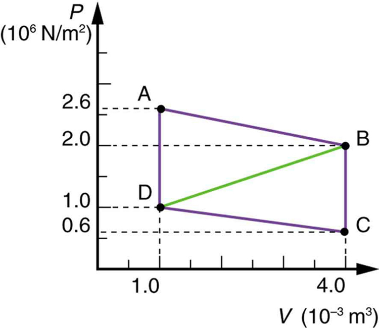
6: What is the net work output of a heat engine that follows path ABDA in the figure above, with a straight line from B to D? Why is the work output less than for path ABCDA? Explicitly show how you follow the steps in the Chapter 15.5 Problem-Solving Strategies for Thermodynamics.
7: Unreasonable Results
What is wrong with the claim that a cyclical heat engine does 4.00 kJ of work on an input of 24.0 kJ of heat transfer while 16.0 kJ of heat transfers to the environment?
8: (a) A cyclical heat engine, operating between temperatures of[latex]\boldsymbol{450^0\textbf{ C}}[/latex]and[latex]\boldsymbol{150^0\textbf{ C}}[/latex]produces 4.00 MJ of work on a heat transfer of 5.00 MJ into the engine. How much heat transfer occurs to the environment? (b) What is unreasonable about the engine? (c) Which premise is unreasonable?
9: Construct Your Own Problem
Consider a car’s gasoline engine. Construct a problem in which you calculate the maximum efficiency this engine can have. Among the things to consider are the effective hot and cold reservoir temperatures. Compare your calculated efficiency with the actual efficiency of car engines.
10: Construct Your Own Problem
Consider a car trip into the mountains. Construct a problem in which you calculate the overall efficiency of the car for the trip as a ratio of kinetic and potential energy gained to fuel consumed. Compare this efficiency to the thermodynamic efficiency quoted for gasoline engines and discuss why the thermodynamic efficiency is so much greater. Among the factors to be considered are the gain in altitude and speed, the mass of the car, the distance traveled, and typical fuel economy.
Glossary
- heat engine
- a machine that uses heat transfer to do work
- isobaric process
- constant-pressure process in which a gas does work
- isochoric process
- a constant-volume process
- isothermal process
- a constant-temperature process
- adiabatic process
- a process in which no heat transfer takes place
- reversible process
- a process in which both the heat engine system and the external environment theoretically can be returned to their original states
Solutions
Problems & Exercises
1:
[latex]\boldsymbol{6.77\times10^3\textbf{ J}}[/latex]
3:
(a)[latex]\boldsymbol{W=P\Delta{V}=1.76\times10^5\textbf{ J}}[/latex]
(b)[latex]\boldsymbol{W=Fd=1.76\times10^5\textbf{ J}}.[/latex]Yes, the answer is the same.
5:
[latex]\boldsymbol{W=4.5\times10^3\textbf{ J}}[/latex]
7:
[latex]\boldsymbol{W}[/latex]is not equal to the difference between the heat input and the heat output.
