Chapter 23 Electromagnetic Induction, AC Circuits, and Electrical Technologies
187 23.8 Electrical Safety: Systems and Devices
Learning Objectives
- Explain how various modern safety features in electric circuits work, with an emphasis on how induction is employed.
Electricity has two hazards. A thermal hazard occurs when there is electrical overheating. A shock hazard occurs when electric current passes through a person. Both hazards have already been discussed. Here we will concentrate on systems and devices that prevent electrical hazards.
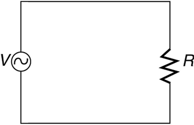
Figure 1 shows the schematic for a simple AC circuit with no safety features. This is not how power is distributed in practice. Modern household and industrial wiring requires the three-wire system, shown schematically in Figure 2, which has several safety features. First is the familiar circuit breaker (or fuse) to prevent thermal overload. Second, there is a protective case around the appliance, such as a toaster or refrigerator. The case’s safety feature is that it prevents a person from touching exposed wires and coming into electrical contact with the circuit, helping prevent shocks.
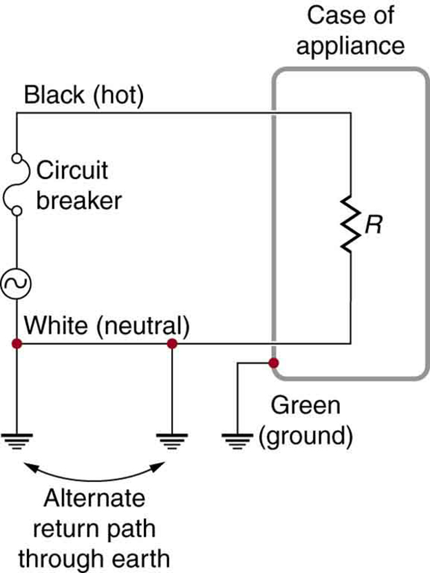
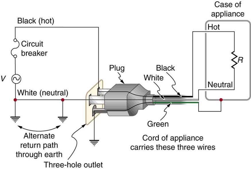
There are three connections to earth or ground (hereafter referred to as “earth/ground”) shown in Figure 2. Recall that an earth/ground connection is a low-resistance path directly to the earth. The two earth/ground connections on the neutral wire force it to be at zero volts relative to the earth, giving the wire its name. This wire is therefore safe to touch even if its insulation, usually white, is missing. The neutral wire is the return path for the current to follow to complete the circuit. Furthermore, the two earth/ground connections supply an alternative path through the earth, a good conductor, to complete the circuit. The earth/ground connection closest to the power source could be at the generating plant, while the other is at the user’s location. The third earth/ground is to the case of the appliance, through the green earth/ground wire, forcing the case, too, to be at zero volts. The live or hot wire (hereafter referred to as “live/hot”) supplies voltage and current to operate the appliance. Figure 3 shows a more pictorial version of how the three-wire system is connected through a three-prong plug to an appliance.
A note on insulation color-coding: Insulating plastic is color-coded to identify live/hot, neutral and ground wires but these codes vary around the world. Live/hot wires may be brown, red, black, blue or grey. Neutral wire may be blue, black or white. Since the same color may be used for live/hot or neutral in different parts of the world, it is essential to determine the color code in your region. The only exception is the earth/ground wire which is often green but may be yellow or just bare wire. Striped coatings are sometimes used for the benefit of those who are colorblind.
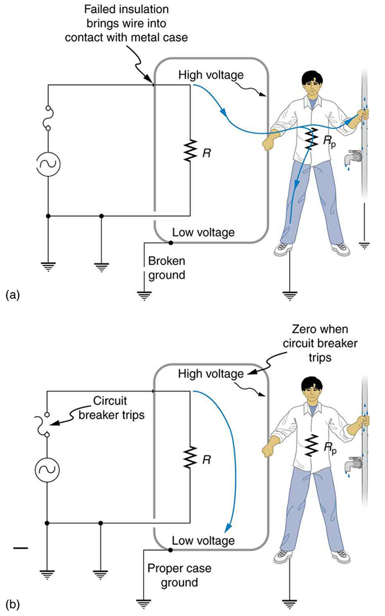
The three-wire system replaced the older two-wire system, which lacks an earth/ground wire. Under ordinary circumstances, insulation on the live/hot and neutral wires prevents the case from being directly in the circuit, so that the earth/ground wire may seem like double protection. Grounding the case solves more than one problem, however. The simplest problem is worn insulation on the live/hot wire that allows it to contact the case, as shown in Figure 4. Lacking an earth/ground connection (some people cut the third prong off the plug because they only have outdated two hole receptacles), a severe shock is possible. This is particularly dangerous in the kitchen, where a good connection to earth/ground is available through water on the floor or a water faucet. With the earth/ground connection intact, the circuit breaker will trip, forcing repair of the appliance. Why are some appliances still sold with two-prong plugs? These have nonconducting cases, such as power tools with impact resistant plastic cases, and are called doubly insulated. Modern two-prong plugs can be inserted into the asymmetric standard outlet in only one way, to ensure proper connection of live/hot and neutral wires.
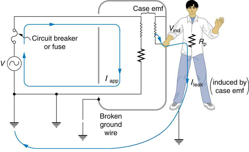
Electromagnetic induction causes a more subtle problem that is solved by grounding the case. The AC current in appliances can induce an emf on the case. If grounded, the case voltage is kept near zero, but if the case is not grounded, a shock can occur as pictured in Figure 5. Current driven by the induced case emf is called a leakage current, although current does not necessarily pass from the resistor to the case.
A ground fault interrupter (GFI) is a safety device found in updated kitchen and bathroom wiring that works based on electromagnetic induction. GFIs compare the currents in the live/hot and neutral wires. When live/hot and neutral currents are not equal, it is almost always because current in the neutral is less than in the live/hot wire. Then some of the current, again called a leakage current, is returning to the voltage source by a path other than through the neutral wire. It is assumed that this path presents a hazard, such as shown in Figure 6. GFIs are usually set to interrupt the circuit if the leakage current is greater than 5 mA, the accepted maximum harmless shock. Even if the leakage current goes safely to earth/ground through an intact earth/ground wire, the GFI will trip, forcing repair of the leakage.
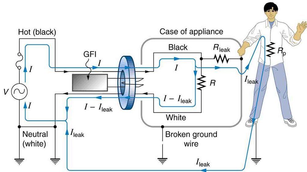
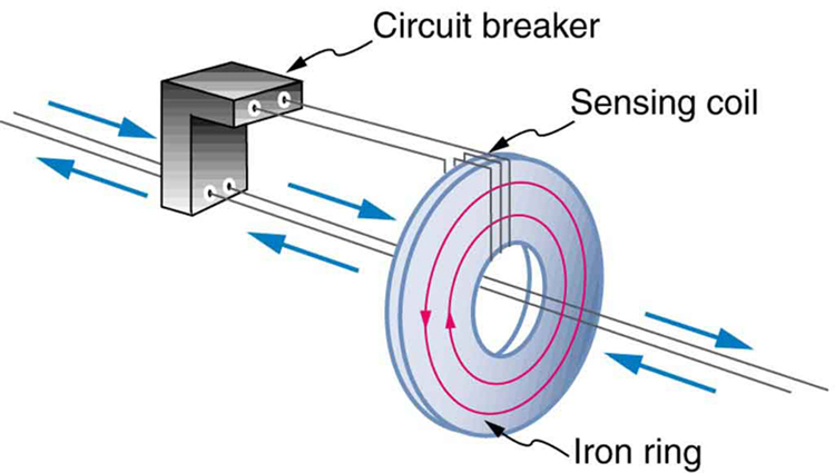
Figure 7 shows how a GFI works. If the currents in the live/hot and neutral wires are equal, then they induce equal and opposite emfs in the coil. If not, then the circuit breaker will trip.
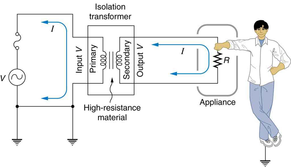
Another induction-based safety device is the isolation transformer, shown in Figure 8. Most isolation transformers have equal input and output voltages. Their function is to put a large resistance between the original voltage source and the device being operated. This prevents a complete circuit between them, even in the circumstance shown. There is a complete circuit through the appliance. But there is not a complete circuit for current to flow through the person in the figure, who is touching only one of the transformer’s output wires, and neither output wire is grounded. The appliance is isolated from the original voltage source by the high resistance of the material between the transformer coils, hence the name isolation transformer. For current to flow through the person, it must pass through the high-resistance material between the coils, through the wire, the person, and back through the earth—a path with such a large resistance that the current is negligible.
The basics of electrical safety presented here help prevent many electrical hazards. Electrical safety can be pursued to greater depths. There are, for example, problems related to different earth/ground connections for appliances in close proximity. Many other examples are found in hospitals. Microshock-sensitive patients, for instance, require special protection. For these people, currents as low as 0.1 mA may cause ventricular fibrillation. The interested reader can use the material presented here as a basis for further study.
Section Summary
- Electrical safety systems and devices are employed to prevent thermal and shock hazards.
- Circuit breakers and fuses interrupt excessive currents to prevent thermal hazards.
- The three-wire system guards against thermal and shock hazards, utilizing live/hot, neutral, and earth/ground wires, and grounding the neutral wire and case of the appliance.
- A ground fault interrupter (GFI) prevents shock by detecting the loss of current to unintentional paths.
- An isolation transformer insulates the device being powered from the original source, also to prevent shock.
- Many of these devices use induction to perform their basic function.
Conceptual Questions
1: Does plastic insulation on live/hot wires prevent shock hazards, thermal hazards, or both?
2: Why are ordinary circuit breakers and fuses ineffective in preventing shocks?
3: A GFI may trip just because the live/hot and neutral wires connected to it are significantly different in length. Explain why.
Problems & Exercises
1: Integrated Concepts
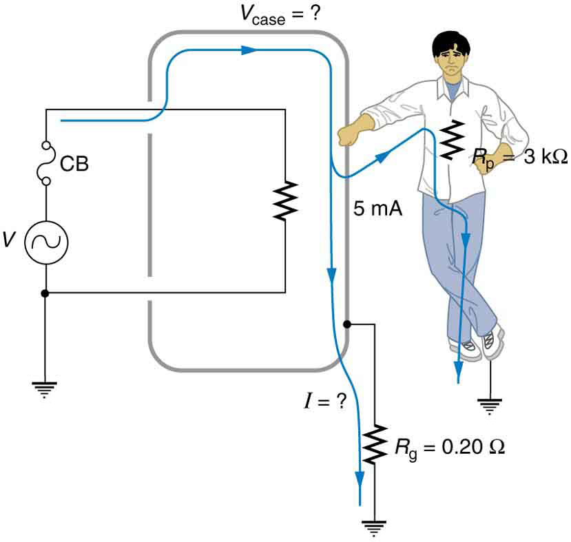
A short circuit to the grounded metal case of an appliance occurs as shown in Figure 9. The person touching the case is wet and only has a
[latex]\boldsymbol{3.00 \;\textbf{k} \Omega}[/latex] resistance to earth/ground. (a) What is the voltage on the case if 5.00 mA flows through the person? (b) What is the current in the short circuit if the resistance of the earth/ground wire is [latex]\boldsymbol{0.200 \;\Omega}[/latex]? (c) Will this trigger the 20.0 A circuit breaker supplying the appliance?
Glossary
- thermal hazard
- the term for electrical hazards due to overheating
- shock hazard
- the term for electrical hazards due to current passing through a human
- three-wire system
- the wiring system used at present for safety reasons, with live, neutral, and ground wires
Solutions
Problems & Exercises
1: (a) 15.0 V
(b) 75.0 A
(c) yes
