Chapter 27 Wave Optics
217 27.5 Single Slit Diffraction
Summary
- Discuss the single slit diffraction pattern.
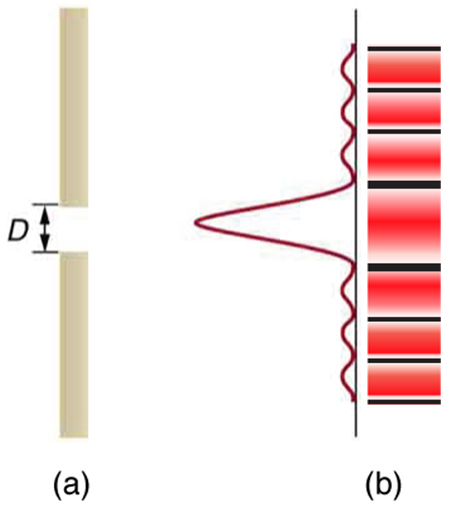
Light passing through a single slit forms a diffraction pattern somewhat different from those formed by double slits or diffraction gratings. Figure 1 shows a single slit diffraction pattern. Note that the central maximum is larger than those on either side, and that the intensity decreases rapidly on either side. In contrast, a diffraction grating produces evenly spaced lines that dim slowly on either side of center.
The analysis of single slit diffraction is illustrated in Figure 2. Here we consider light coming from different parts of the same slit. According to Huygens’s principle, every part of the wavefront in the slit emits wavelets. These are like rays that start out in phase and head in all directions. (Each ray is perpendicular to the wavefront of a wavelet.) Assuming the screen is very far away compared with the size of the slit, rays heading toward a common destination are nearly parallel. When they travel straight ahead, as in Figure 2(a), they remain in phase, and a central maximum is obtained. However, when rays travel at an angle [latex]\boldsymbol{\theta}[/latex] relative to the original direction of the beam, each travels a different distance to a common location, and they can arrive in or out of phase. In Figure 2(b), the ray from the bottom travels a distance of one wavelength [latex]\boldsymbol{\lambda}[/latex] farther than the ray from the top. Thus a ray from the center travels a distance [latex]\boldsymbol{\lambda /2}[/latex] farther than the one on the left, arrives out of phase, and interferes destructively. A ray from slightly above the center and one from slightly above the bottom will also cancel one another. In fact, each ray from the slit will have another to interfere destructively, and a minimum in intensity will occur at this angle. There will be another minimum at the same angle to the right of the incident direction of the light.
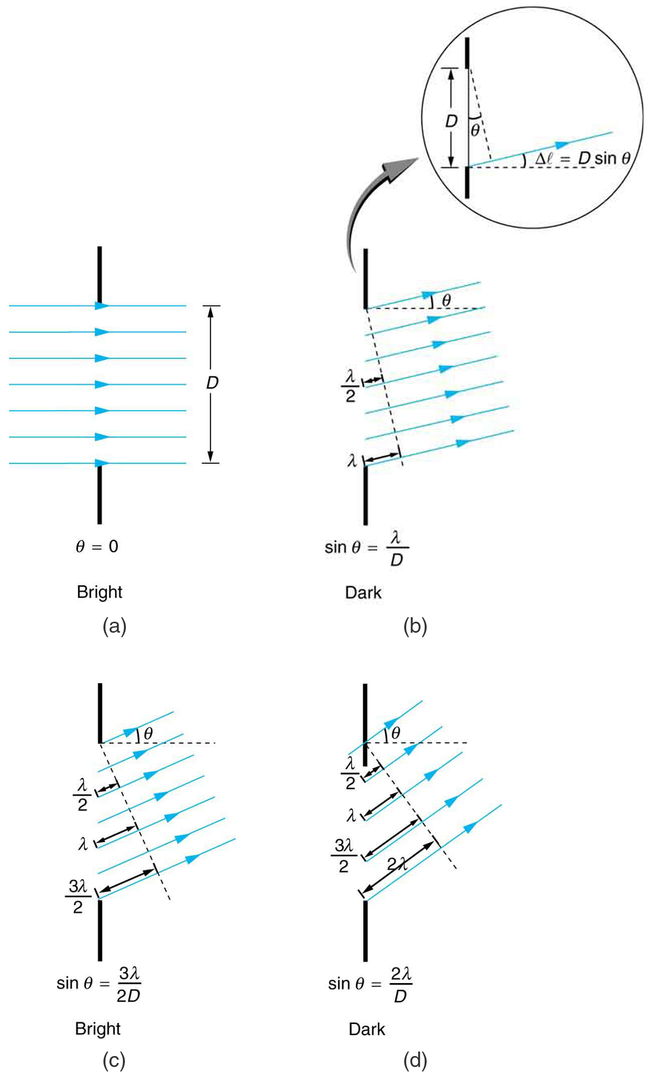
At the larger angle shown in Figure 2(c), the path lengths differ by [latex]\boldsymbol{3 \lambda/2}[/latex] for rays from the top and bottom of the slit. One ray travels a distance [latex]\boldsymbol{\lambda}[/latex] different from the ray from the bottom and arrives in phase, interfering constructively. Two rays, each from slightly above those two, will also add constructively. Most rays from the slit will have another to interfere with constructively, and a maximum in intensity will occur at this angle. However, all rays do not interfere constructively for this situation, and so the maximum is not as intense as the central maximum. Finally, in Figure 2(d), the angle shown is large enough to produce a second minimum. As seen in the figure, the difference in path length for rays from either side of the slit is [latex]\boldsymbol{D \;\textbf{sin} \;\theta}[/latex], and we see that a destructive minimum is obtained when this distance is an integral multiple of the wavelength.
Thus, to obtain destructive interference for a single slit,
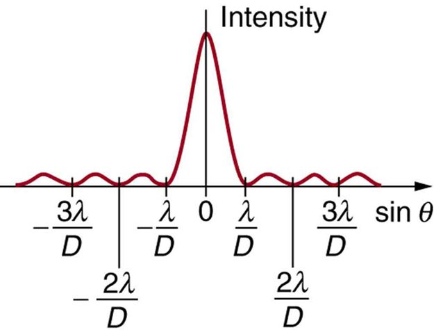
where [latex]\boldsymbol{D}[/latex] is the slit width, [latex]\boldsymbol{\lambda}[/latex] is the light’s wavelength, [latex]\boldsymbol{\theta}[/latex] is the angle relative to the original direction of the light, and mm size 12{m} {} is the order of the minimum. Figure 3 shows a graph of intensity for single slit interference, and it is apparent that the maxima on either side of the central maximum are much less intense and not as wide. This is consistent with the illustration in Figure 1(b).
Example 1: Calculating Single Slit Diffraction
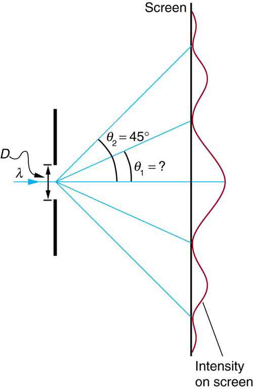
Visible light of wavelength 550 nm falls on a single slit and produces its second diffraction minimum at an angle of [latex]\boldsymbol{45.0 ^{\circ}}[/latex] relative to the incident direction of the light. (a) What is the width of the slit? (b) At what angle is the first minimum produced?
Strategy
From the given information, and assuming the screen is far away from the slit, we can use the equation [latex]\boldsymbol{D \;\textbf{sin} \;\theta = m \lambda}[/latex] first to find [latex]\boldsymbol{D}[/latex], and again to find the angle for the first minimum [latex]\boldsymbol{\theta _1}[/latex].
Solution for (a)
We are given that [latex]\boldsymbol{\lambda = 550 \;\textbf{nm}}[/latex], [latex]\boldsymbol{m = 2}[/latex], and [latex]\boldsymbol{\theta _2 = 45.0^{\circ}}[/latex]. Solving the equation [latex]\boldsymbol{D \;\textbf{sin} \;\theta = m \lambda}[/latex] and substituting known values gives
Solution for (b)
Solving the equation [latex]\boldsymbol{D \;\textbf{sin} \;\theta = m \theta}[/latex] for [latex]\boldsymbol{\textbf{sin} \;\theta _1}[/latex] and substituting the known values gives
Thus the angle [latex]\boldsymbol{\theta _1}[/latex] is
Discussion
We see that the slit is narrow (it is only a few times greater than the wavelength of light). This is consistent with the fact that light must interact with an object comparable in size to its wavelength in order to exhibit significant wave effects such as this single slit diffraction pattern. We also see that the central maximum extends [latex]\boldsymbol{20.7 ^{\circ}}[/latex] on either side of the original beam, for a width of about [latex]\boldsymbol{41 ^{\circ}}[/latex]. The angle between the first and second minima is only about [latex]\boldsymbol{24^{\circ} \; (45.0^{\circ} - 20.7^{\circ})}[/latex]. Thus the second maximum is only about half as wide as the central maximum.
Section Summary
- A single slit produces an interference pattern characterized by a broad central maximum with narrower and dimmer maxima to the sides.
- There is destructive interference for a single slit when
[latex]\boldsymbol{D \;\textbf{sin} \;\theta = m \lambda , \; (\textbf{for} \; m = \; 1, \; -1, \; 2, \; -2, \; 3, \; \dots)}[/latex], where [latex]\boldsymbol{D}[/latex] is the slit width, [latex]\boldsymbol{\lambda}[/latex] is the light’s wavelength, [latex]\boldsymbol{\theta}[/latex] is the angle relative to the original direction of the light, and [latex]\boldsymbol{m}[/latex] is the order of the minimum. Note that there is no [latex]\boldsymbol{m = 0}[/latex] minimum.
Conceptual Questions
1: As the width of the slit producing a single-slit diffraction pattern is reduced, how will the diffraction pattern produced change?
Problems & Exercises
1: (a) At what angle is the first minimum for 550-nm light falling on a single slit of width [latex]\boldsymbol{1.00 \;\mu \textbf{m}}[/latex]? (b) Will there be a second minimum?
2: (a) Calculate the angle at which a [latex]\boldsymbol{2.00 - \mu \textbf{m}}[/latex] -wide slit produces its first minimum for 410-nm violet light. (b) Where is the first minimum for 700-nm red light?
3: (a) How wide is a single slit that produces its first minimum for 633-nm light at an angle of [latex]\boldsymbol{28.0 ^{\circ}}[/latex]? (b) At what angle will the second minimum be?
4: (a) What is the width of a single slit that produces its first minimum at [latex]\boldsymbol{60.0 ^{\circ}}[/latex] for 600-nm light? (b) Find the wavelength of light that has its first minimum at [latex]\boldsymbol{62.0 ^{\circ}}[/latex].
5: Find the wavelength of light that has its third minimum at an angle of [latex]\boldsymbol{48.6 ^{\circ}}[/latex] when it falls on a single slit of width [latex]\boldsymbol{3.00 \;\mu \textbf{m}}[/latex].
6: Calculate the wavelength of light that produces its first minimum at an angle of [latex]\boldsymbol{36.9 ^{\circ}}[/latex] when falling on a single slit of width [latex]\boldsymbol{1.00 \;\mu \textbf{m}}[/latex].
7: (a) Sodium vapor light averaging 589 nm in wavelength falls on a single slit of width [latex]\boldsymbol{7.50 \;\mu \textbf{m}}[/latex]. At what angle does it produces its second minimum? (b) What is the highest-order minimum produced?
8: (a) Find the angle of the third diffraction minimum for 633-nm light falling on a slit of width [latex]\boldsymbol{20.0 \;\mu \textbf{m}}[/latex]. (b) What slit width would place this minimum at [latex]\boldsymbol{85.0 ^{\circ}}[/latex]? Explicitly show how you follow the steps in Chapter 27.7 Problem-Solving Strategies for Wave Optics
9: (a) Find the angle between the first minima for the two sodium vapor lines, which have wavelengths of 589.1 and 589.6 nm, when they fall upon a single slit of width [latex]\boldsymbol{2.00 \;\mu \textbf{m}}[/latex]. (b) What is the distance between these minima if the diffraction pattern falls on a screen 1.00 m from the slit? (c) Discuss the ease or difficulty of measuring such a distance.
10: (a) What is the minimum width of a single slit (in multiples of [latex]\boldsymbol{\lambda}[/latex]) that will produce a first minimum for a wavelength [latex]\boldsymbol{\lambda}[/latex]? (b) What is its minimum width if it produces 50 minima? (c) 1000 minima?
11: (a) If a single slit produces a first minimum at [latex]\boldsymbol{14.5 ^{\circ}}[/latex], at what angle is the second-order minimum? (b) What is the angle of the third-order minimum? (c) Is there a fourth-order minimum? (d) Use your answers to illustrate how the angular width of the central maximum is about twice the angular width of the next maximum (which is the angle between the first and second minima).
12: A double slit produces a diffraction pattern that is a combination of single and double slit interference. Find the ratio of the width of the slits to the separation between them, if the first minimum of the single slit pattern falls on the fifth maximum of the double slit pattern. (This will greatly reduce the intensity of the fifth maximum.)
13: Integrated Concepts
A water break at the entrance to a harbor consists of a rock barrier with a 50.0-m-wide opening. Ocean waves of 20.0-m wavelength approach the opening straight on. At what angle to the incident direction are the boats inside the harbor most protected against wave action?
14: Integrated Concepts
An aircraft maintenance technician walks past a tall hangar door that acts like a single slit for sound entering the hangar. Outside the door, on a line perpendicular to the opening in the door, a jet engine makes a 600-Hz sound. At what angle with the door will the technician observe the first minimum in sound intensity if the vertical opening is 0.800 m wide and the speed of sound is 340 m/s?
Glossary
- destructive interference for a single slit
- occurs when [latex]\boldsymbol{D \;\textbf{sin} \; \theta = m \lambda , \; ( \textbf{for} \; m = \; 1, \; -1, \; 2, \; -2, \; 3, \; \dots )}[/latex] , where [latex]\boldsymbol{D}[/latex] is the slit width, [latex]\boldsymbol{\lambda}[/latex] is the light’s wavelength, [latex]\boldsymbol{\theta}[/latex] is the angle relative to the original direction of the light, and [latex]\boldsymbol{m}[/latex] is the order of the minimum
Solutions
Problems & Exercises
1: (a) [latex]\boldsymbol{33.4 ^{\circ}}[/latex]
(b) No
3: (a) [latex]\boldsymbol{1.35 \times 10^{-6} \;\textbf{m}}[/latex]
(b) [latex]\boldsymbol{69.9 ^{\circ}}[/latex]
5: 750 nm
7: (a) [latex]\boldsymbol{9.04 ^{\circ}}[/latex]
(b) 12
9: (a) [latex]\boldsymbol{0.0150 ^{\circ}}[/latex]
(b) 0.262 mm
(c) This distance is not easily measured by human eye, but under a microscope or magnifying glass it is quite easily measurable.
11: (a) [latex]\boldsymbol{30.1 ^{\circ}}[/latex]
(b) [latex]\boldsymbol{48.7 ^{\circ}}[/latex]
(c) No
(d) [latex]\boldsymbol{2 \theta _1 = (2)(14.5 ^{\circ}) = 29 ^{\circ}, \theta _2 - \theta _1 =30.05 ^{\circ} - 14.5 ^{\circ} = 15.56^{\circ}}[/latex]. Thus, [latex]\boldsymbol{29 ^{\circ} \approx (2)(15.56 ^{\circ}) = 31.1 ^{\circ}}[/latex].
13: [latex]\boldsymbol{23.6 ^{\circ}}[/latex]
