Main Body
Properties of Areas
Inertia Moment
Learning Objectives
Upon completion of this chapter you should be able to
- Determine the centroid location of a given cross-section
- Calculate the moment of inertia for a given cross-section, with both SI and US Customary units
Finding the location of the centroid is needed when calculating the moment of inertia (or second moment of areas) of beams subjected to bending. For convenience, you may used the table provided in Appendix 1.
The geometric properties of areas for common shapes are given in textbook Appendix C. Common industrial shapes like W-beams and pipes are listed in Appendix D.
Determining the location of the centroid of a composite area uses the concept of moment of an area; this is why textbooks may refer to this as “first moments of areas”. Mathematically this principle is expressed as:
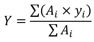
where:
- Y is the distance to the centroid from some reference axis. Commonly, the reference axis is the base of the figure.
- Ai is the area of one part of the composite area. Typically, the composite areas are split into common shapes of known geometric properties, summarized in the textbook Appendix C.
- yi is the distance from the reference axis (commonly the base of the figure) to the centroid of each part of the composite figure.
- Σ(Ai) is the entire area of the composite area.
When determining the location of a centroid please observe the following rules:
- If the cross-section has one axis of symmetry then the centroid will be located on this axis.
- if the cross-section has two axes of symmetry then the centroid will be located at the intersection of the two axes.
- If the cross-section is not symmetric about any axis then two calculations are required:
- one for determining the centroid location Y
- one for determining the centroid location X, commonly measured from the extreme left end. For this second calculation imagine that you rotate the figure 90º counter-clockwise and repeat the first calculation
- If the composite area has a part that is removed from the figure (a void), this missing part can be treated as a negative area.
In rotational kinetics we learned that the “rotational” moment of inertia of a flywheel (function of its mass, size and shape) represents a resistance to change in its motion. This moment of inertia multiplied by the angular acceleration α, gives an inertia-moment reaction that attempts to balance the accelerating moment action (accelerating torque). In general, a moment of inertia is a resistance to change.
Beams are subject to bending and as a result they tend to deform (deflect). The moment of inertia of a beam cross-section can be related to the stiffness of the beam. The deflection of the beam is inverse proportional to the moment of inertia.
Formulas for moments of inertia of simple shapes are given in Textbook Appendix C. They will also be provided in the exam.
When dealing with a composite area, divide the shape into basic parts for which the moment of inertia can be easily calculated. The combined moment of inertia of the entire shape is the sum of moments of inertia of constituent parts plus their corresponding transfer term. The transfer term is calculated as the area of the part multiplied by the squared distance between the centroid of the part and the common centroid of the entire area. This transfer term represents the additional stiffness of each part due to its relative distance from the common centroid. The table given in Supplement Appendix 1 can be used for calculations; it is useful when the shape is more complex.
Assigned Problems
When completing these exercises please make sure that you clearly identify and number the parts of your composite area.
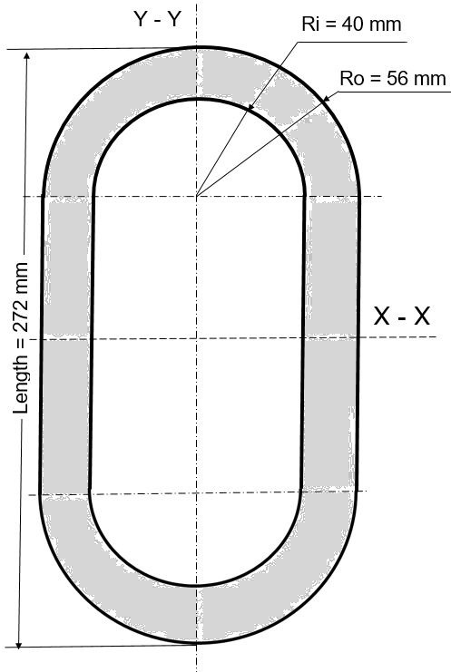
Problem 1: Determine the moment of inertia about the vertical and horizontal centroidal axes for the following figure.
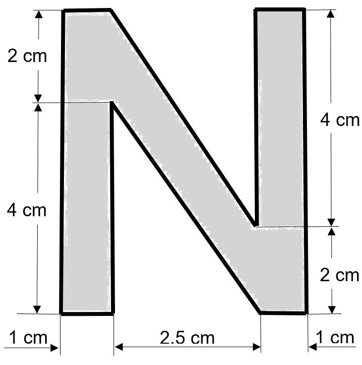
Problem 2: For the following cross-section determine the location (elevation) of the centroid and the moments of inertia with respect to the horizontal and vertical centroidal axes.
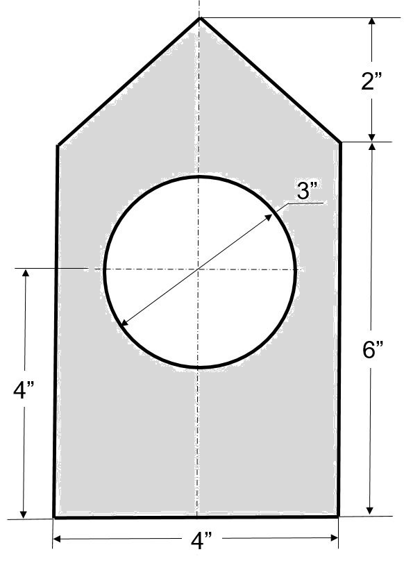
Problem 3: For the following figure determine Y, the vertical location of the centroid, and calculate the moment of inertia with respect to the horizontal centroidal axis..
Problem 4: Suggest one improvement to this chapter; this may include an original cross-section.
