Main Body
Stress and Strain
Stress-Strain
Learning Objectives
After completing this chapter you should be able to:
- Define normal and shear stress and strain and discuss the relationship between design stress, yield stress and ultimate stress
- Design members under tension, compression and shear loads
- Determine members deformation under tension and compression
Tension or compression in a member generate normal stresses; they are called “normal” because the cross-section that resists the load is perpendicular (normal) to the direction of the applied forces. Both tensile and compressive stresses are calculated with:
![]()
If a member has a variable cross-section, the area that must be used in calculations is the minimum cross-sectional area; this will give you the maximum stress in the member, which ultimately will govern the design.
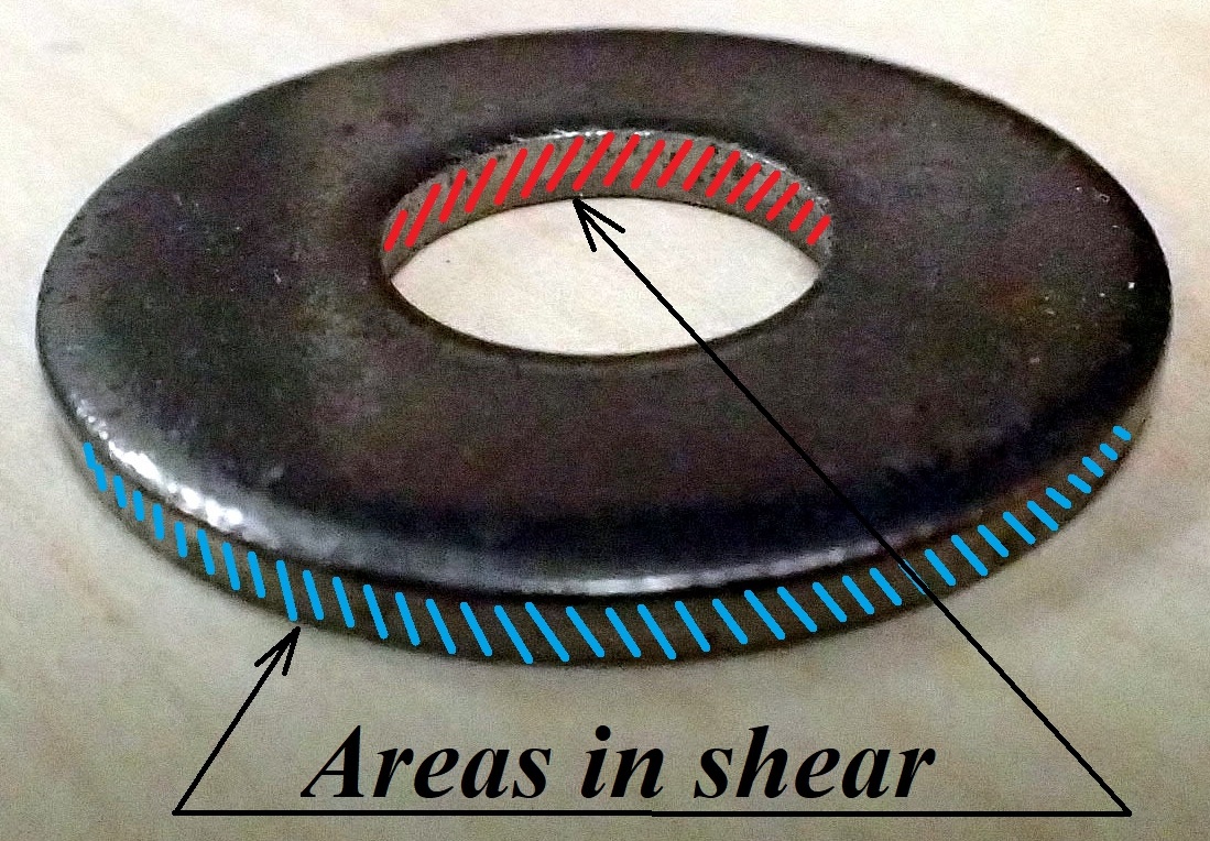
Shear stresses
In shear the cross-section area that resists the load is parallel with the direction of applied forces. In addition to that, when estimating the shear area you must factor in how many cross-sections contribute to the overall strength of the assembly.
For instance, if you consider the pin of a door hinge as subjected to a shear load, you have to count how many cross-sections resist the load.
The formula for calculating the shear stress is the same:
![]()
In a punching operation the area that resists the shear is in the shape of a cylinder for a round hole (think of a cookie cutter). Therefore the area in shear will be found from multiplying the circumference of the shape by the thickness of the plate.
Please note:
When looking at textbook figures you will observe that two forces are indicated. This does not mean that the force you use in the formula is (2 × Force P), but simply indicates that one is the Action force and the second one is the Reaction.
Normal strain
A member in tension or compression will elastically deform proportional with, among other parameters, the original length. Strain, also called unit deformation, is a non-dimensional parameter expressed as:
![]()
If you choose to use a negative value for compression strain (reduction in length) then you must also express the equivalent compression stress as a negative value.
The stress – strain curve is generated from the tensile test. Over the elastic region of the graph the deformation is direct proportional with the load. Dividing the load by the cross-section area (constant) and the deformation by the original length (constant) leads to a graphical representation of Strain vs. Stress. The constant ratio of stress and strain is Young’s Modulus or Elastic Modulus, a property of each material.
![]()
Combining the above two relations for strain and Modulus of Elasticity leads to a unified formula for elastic deformation in tension or compression.
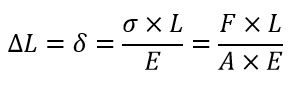
This relation is applicable to members with uniform cross-sections, homogeneous material, subject to tensile or compressive loads that results in stresses below the proportional limit (straight line in the σ-ε curve).
These topics were covered in 1st year Strength of Materials and are presented here as a brief review.
Members subjected to an excessive stress may fail by breaking, when actual working stress is greater than the ultimate stress, or due to excessive deformation that renders then inoperable. Consider a heavy condensate line that sags beyond an acceptable limit and while it doesn’t break, the flange connections at the end of the lines will develop leaks due to angular movement.
Design stress, σd, is the maximum level of actual/working stress that is considered acceptable from a safety point of view. The design stress is determined by:
- Material properties, Ultimate Tensile Strength or Yield Strength, depending if breakage must be avoided or deformation must be limited
- Safety factor (or design factor) N, ratio of maximum strength to the intended load.
The safety factor is chosen by the designer based on experience, judgment AND guidelines/rules from relevant codes and standards, based on several criteria such as risk of injuries, design data accuracy, probability, industry standards, and last but not least, cost. Safety factors standards were set by structural engineers, based on rigorous estimates and backed by years of experience. Standards are continuously evolving reflecting new and improved design philosophies. Example:
- published by ANSI / AISC , such as Specification for Structural Steel Buildings
When solving problems students may encounter different scenarios. While the theoretical concepts are the same, the paths to final answers may be different, as required by each approach.
- Estimating if a design/construction is safe or not
- Given: loads magnitude and distribution, material properties, member shape and dimensions
- Find: actual stress and compare to the design stress; alternatively find the safety factor and decide if it is acceptable based on applicable standards
- Selecting a suitable material
- Given: loads magnitude and distribution, member shape and dimensions
- Find: what material type or grade will provide a strength (yield or ultimate) greater than required, while considering the selected or specified safety factor
- Determining the shape and dimensions of member’s cross-section
- Given: loads magnitude and distribution, material properties
- Find: the shape and dimensions of the member so that actual cross-sectional area is greater than minimum required.
- Evaluating maximum allowable load on a component
- Given: load type and distribution, material properties, member shape and dimensions
- Find: maximum load magnitude that leads to an acceptable stress
There are cases when a member under normal stresses is made out of two (or more) materials. One of the objective of such problems is to find the stress in each component.
For example, you may have a short column made from a steel pipe filled with concrete, as in the figure. Given the total load, materials properties and geometrical dimensions, we must find the individual stress in each component.
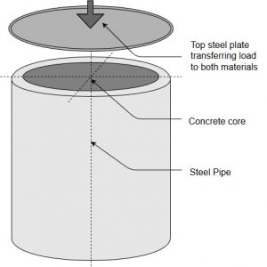
Both, the steel pipe and the concrete core work together in supporting the load therefore we must find additional relations that combine the two problems into one . Typically, we look for:
- a relation that describes the force distribution between the two materials
- a relation that correlates the deformations of each material
For this particular problem we may say that:
Equation 1: Total load P = load supported by steel P steel + load supported by concrete P concrete
therefore P = Stress steel × Area steel + Stress concrete × Area concrete
Equation 2: The deformations of both materials are the same
therefore Strain steel = Strain concrete
Considering that Elastic Modulus = Stress / Strain, equation (2) yields a relation between the stress and elasticity of both materials
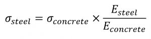
Substituting this last relation into equation (1) and solving for Stress concrete leads to a relation as follows
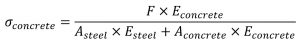
Further, Stress steel can be found.
Note that depending on the problem, the original two relations may be different therefore a full step-by-step derivation may be required each time.
Reasonable answers
When solving normal stress – strain problems, especially in the SI system, you should be able to judge if your answers are reasonable or not.
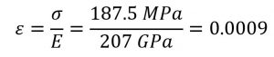
Example: A 1 m long, 20 mm diameter, A 36 Carbon Steel bar (Materials Properties in Appendix B, Table B2) suspends a 6 tons load. Evaluate the stress and the strain in the bar.
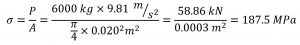
Note that typically loads are in kN, cross-section areas in 10-3 m2 and resulting stresses in MPa.
Also, since Elastic Moduli are in GPa, the strain (non-dimensional) will be in range of 10-3. This bar will stretch 0.9 mm under the given load.
Assigned Problems
When solving these questions you are required to use the textbook Appendices. They are valuable references for material properties, geometrical dimensions, etc.
Problem 1: A condensate line 152 mm nominal size made of schedule 40 carbon steel pipe is supported by threaded rod hangers spaced at 2.5 m center-to-center. The hangers are carbon steel, 50 cm long, with a root diameter of 12 mm. Calculate the stress and the strain in the hangers. Use E=200 GPa for the hangers material.
Problem 2: A clevis fastener with a 1/2 inch pin is used in a shop lifting machine. If the pin is made of A36 steel determine the maximum safe load, using a safety factor of 2.5 based on the yield strength.
Problem 3: A boiler is supported on several short columns as indicated in the figure, made out of Class 35 gray cast iron. Each column supports a load of 50 tonnes. The required safety factor for this construction is 3. Are the columns safe?
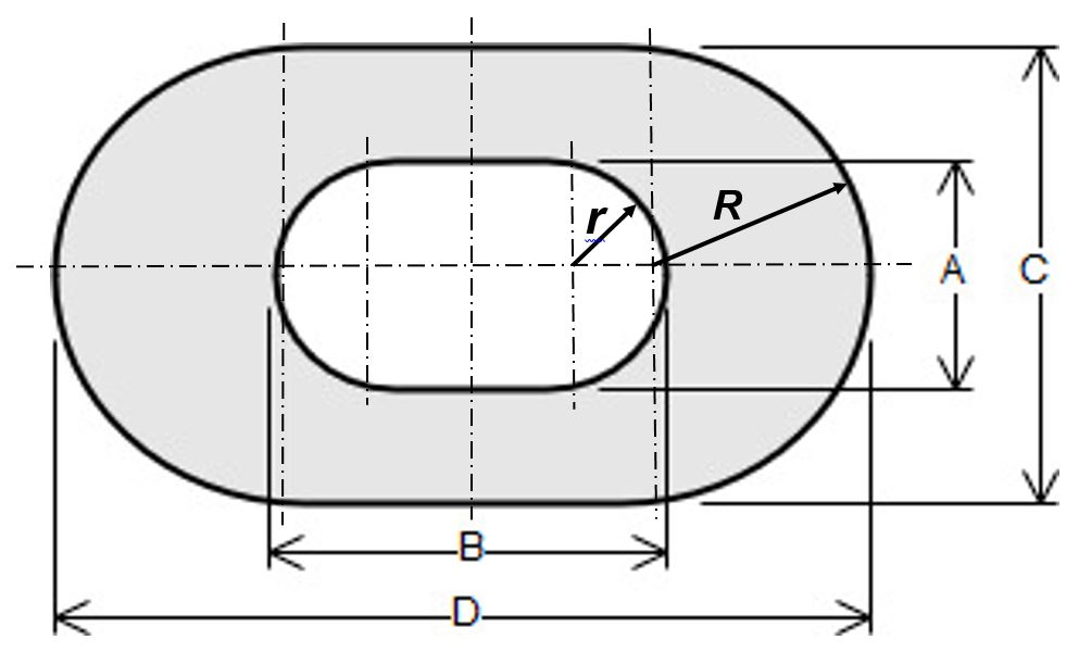
Use the following dimensions: A = 30 mm, B = 80 mm, C = 50 mm, D = 140 mm
Problem 4: A tension member in a roof truss is subject to a load of 25 kips. The construction requires using L2x2x1/4 angle, with a cross-section of 0.944 in2. For building-like structures American Institute of Steel Construction recommends using a design stress of 0.60×Sy. Using Appendix B table B2 specify a suitable steel material.
Problem 5: A tie rod hydraulic cylinder as in the figure is made from a 6 inch Schedule 40 stainless steel pipe, 15 inches long. The six tie rods are 1/2-13 UNC threaded rods with a root diameter of 0.4822 inch and a thread pitch of 13 TPI. When assembling the cylinder a clamping force equivalent to one full nut turn from hand-tight position is required.
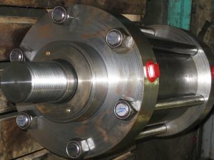
Determine the stress in the cylinder and in the tie rods. Also calculate the strain in each component using an elastic modulus of Ess = 28×106 psi and Erod = 30×106 psi.
Problem 6: Suggest one improvement to this chapter.
